
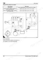
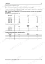
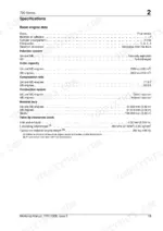
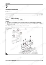
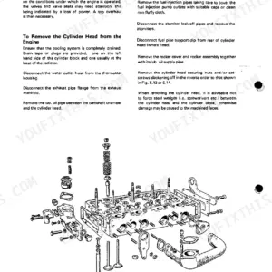
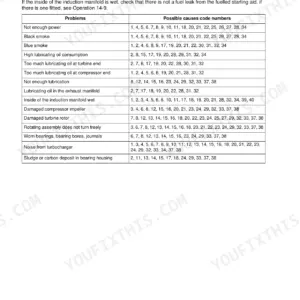
Rebuilding a Perkins 700 Series diesel, UA, UB or UC? This 206-page shop manual PDF (OEM #TPD 1392E) runs system by system, cylinder head through flywheel housing, on both naturally aspirated and turbocharged builds. It carries factory wiring diagrams for the glowplug and starter circuits, a full section of recommended torque tensions and compression test data, plus step-by-step teardown procedures for the crankshaft, timing case, and fuel injection pump. Set UA and UC atomisers to 190 bar at stage one and 230 bar at stage two (the UB is single-stage), then verify fuel lift pump static pressure between 42 and 70 kPa. A worn injector doesn't announce itself; the spec sheet finds it. Bookmarked by system, so you can jump straight to the fuel or cooling chapter. Download it, load it on your tablet, and get that engine back under load.
What's Inside This Perkins 700 Series (UA, UB, UC) Manual
| System | Pages | Key Topics |
|---|---|---|
| General Information | 13-24 | Introduction, Engine Views - Naturally Aspirated Engine, Engine Views - Turbocharged Engine, Engine I.D. Location, Safety Precautions, Viton Seals, Engine Lift Equipment |
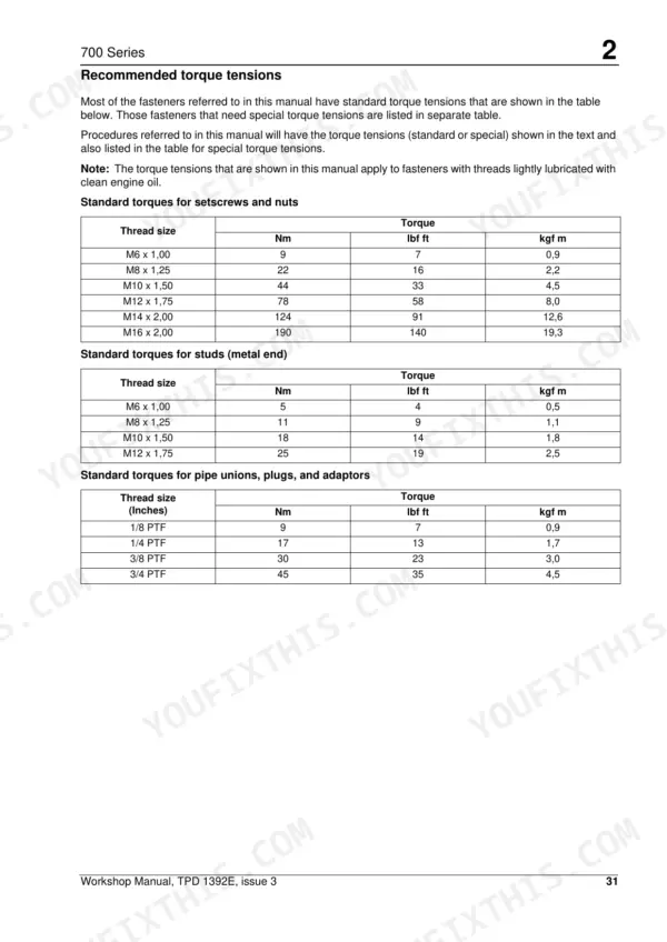
| Specifications | 25-46 | Basic Engine Data, Data and Dimensions, Thread Sealant, Recommended Torque Tensions, Compression Test Data |
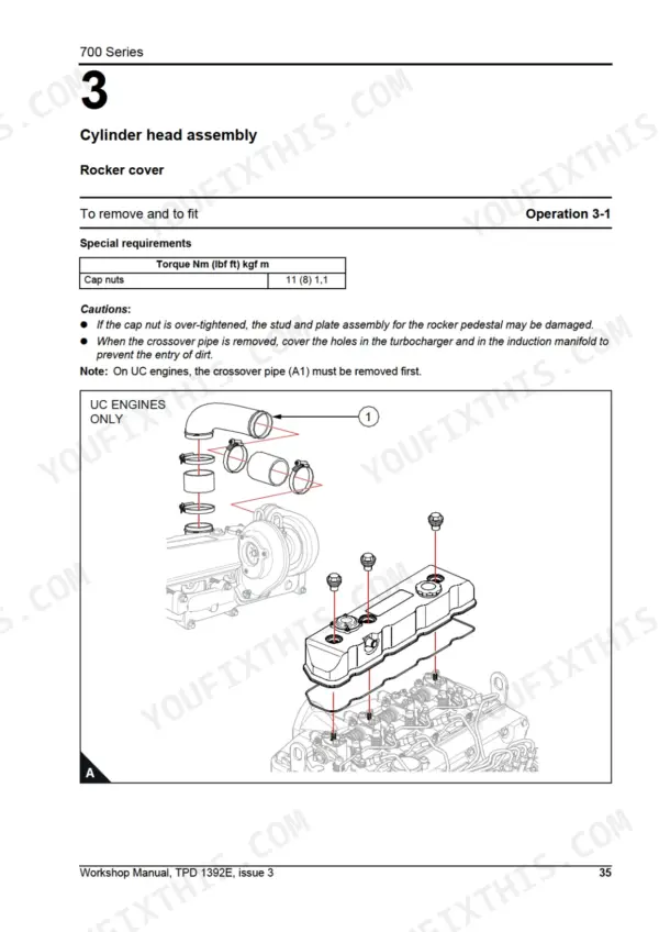
| Cylinder Head Assembly | 47-66 | Rocker Cover, Rocker Assembly, Rocker Shaft, Valve Tip Clearance, Valve Springs, Exhaust / Induction Manifolds and Gasket, Cylinder Head Setscrews, Cylinder Head Gasket |
| Piston and Connecting Rod Assemblies | 67-88 | Big End Bearing and Cap, Piston and Connecting Rod, Piston and Piston Rings, Piston Rings, Connecting Rod, Small End Bush, Piston Height Above the Cylinder Block |
| Crankshaft Assembly | 89-106 | Crankshaft Pulley, Rear Oil Seal, Thrust Washers and Crankshaft End-Float, Thrust Washers, Main Bearing Caps, Main Bearings, Crankshaft, Wear Sleeve |
| Timing Case and Drive Assembly | 107-122 | Tamper Proof Screws, Timing Case, Gear Teeth Meshing, Front Oil Seal, Idler Gear, Idler Gear Bushes, Idler Gear Hub, Camshaft Assembly for the Fuel Injection Pump |
| Cylinder Block Assembly | 123-126 | Cylinder Block Bores, Camshaft Bores |
| Engine Timing | 127-134 | To Set Approximately Number 1 Piston to TDC on the Compression Stroke, Valve Timing, Fuel Injection Pump Timing |
| Aspiration System | 135-142 | Turbocharger, Impeller and Compressor Casing, Engine Breather Assembly |
| Lubrication System | 143-152 | Oil Filter Canister, Engine Lubricating Oil, Filter Head and Oil Cooler, Aluminium Sump, Steel Sump, Oil Strainer and Suction Pipe, Lubricating Oil Pump, Relief Valve |
| Fuel System | 153-178 | Fuel Filter Element, Atomiser Fault, High Pressure Fuel Pipes, Leak Off Rail, Atomisers, Fuel Lift Pump, Fuel Injection Pump, Governor Weight Assembly |
| Cooling System | 179-184 | Coolant, Thermostat, Fan, Coolant Pump, Oil Cooler |
| Flywheel and Housing | 185-188 | Flywheel, Starter Ring, Flywheel Housing |
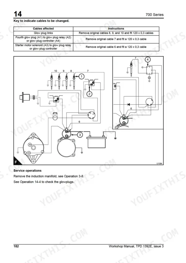
| Electrical Equipment | 189-198 | Drive Belt, Alternator, Glowplugs, Starter Motor, Electrical Stop Solenoid |
| Auxiliary Equipment | 199-200 | Power Take-Off Assembly |
| Special Tools | 201-206 | Special Tools List |
Quick Reference Specifications
| Specification | Value | Page |
|---|---|---|
| Static pressure: No delivery | 42/70 kPa (6/10 lbf/in2) 0,4/0,7 kgf/cm2 | p. 40 |
| Static pressure: Test pressure 75% of minimum static pressure | 31 kPa (4.5 lbf/in2) 0,32 kgf/cm2 | p. 40 |
| Maximum starter cable resistance at 20 °C (68 °F) | 0.0012 ohm | p. 41 |
| Set pressure (Stage one) for UA, UC engines | 190 bar (2793 lbf/in2) 19,25 MPa | p. 40 |
| Set pressure (Stage two) for UA, UC engines | 230 bar (3381 lbf/in2) 23,3 MPa | p. 40 |
| Start to open temperature (82,0 °C nominal) | 77/85 °C (170.6/185.0 °F) | p. 40 |
| Fully open temperature (82,0 °C nominal) | 92/98 °C (197.6/208.4 °F) | p. 40 |
| Glow plug nuts | 2 Nm (18 lbf in) | p. 180 |
| High-pressure fuel pipes union nuts | 27 Nm (37 lbf ft) | p. 180 |
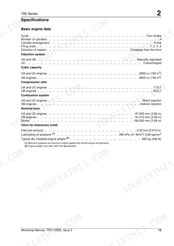
| Lubricating oil pressure | 280 kPa | p. 25 |
| Typical dry installed engine weight | 200 kg | p. 25 |
| Valve tip clearance (cold) | 0,35 mm | p. 25 |
Perkins 700 Series (UA, UB, UC) Common Problems This Manual Covers
Perkins 700 Series diesel cranks slowly in cold weather, glow plugs seem dead, engine won't fire
Start at the battery: confirm charge and clean both cable terminals. Measure total starter cable resistance; anything over 0.0012 ohm at 20 °C (68 °F) kills cranking speed, so replace corroded cables. Test the 12V starter motor on the engine using the electrical equipment procedures starting on page 189, then check glow plug power supply and continuity.
Manual Section: Electrical Equipment p. 189Engine starts then dies after fuel filter change, needs repeated bleeding to run
Look at the tank vent for restriction and drain water from the fuel filter. Bleed air at the filter and injection pump, working through the fuel system procedures starting on page 153. Test lift pump static pressure with no delivery; readings outside 42/70 kPa (6/10 lbf/in2) point to a worn diaphragm, so replace the pump.
Manual Section: Fuel System p. 153Engine overheats under load even with the radiator full, temperature gauge climbs at idle
Top up the coolant and clear debris from the radiator core first. Remove the thermostat and test it in heated water; the 82 °C unit must start opening at 77/85 °C and reach full open by 92/98 °C with at least 9 mm (0.35 in) of valve lift. Replace a failed unit and torque the coolant outlet to 28 Nm (20 lbf ft).
Manual Section: Cooling System p. 179Low oil pressure warning at idle when hot, gauge needle flickers
Confirm oil level and the correct grade before condemning anything. Verify the reading with a test gauge against the 280 kPa lubricating oil pressure spec on page 25. If pressure stays low, drop the sump and inspect the strainer, suction pipe, relief valve, and oil pump using the lubrication system procedures on page 143.
Manual Section: Lubrication System p. 143Low power and black smoke under load, poor compression on one or more cylinders
Set valve tip clearances with the engine cold, each to 0,35 mm, following the cylinder head procedures starting on page 47. Run a compression test to isolate weak cylinders; low readings across all of them suggest valve timing or head gasket trouble. Inspect for sticking valves and induction leaks at the manifold gasket before pulling the head.
Manual Section: Cylinder Head Assembly p. 47Frequently Asked Questions
How do you bleed air from the fuel system on a Perkins 700 Series engine?
To eliminate air, loosen the vent plug on the side of the fuel injection pump. Operate the priming lever until fuel, free of air, comes from the vent point, then tighten the vent plug. If the engine does not start, operate the starter motor for intervals of 15 seconds until it starts, allowing the electrical components to cool for 30 seconds between each interval. p. 164
What does the UA, UB, or UC engine code mean on a Perkins 700 Series?
The engine codes identify the specific configuration: UA is a 3.0 litre direct injection engine, UB is a 2.6 litre indirect injection engine, and UC is a 3.0 litre turbocharged direct injection engine. p. 13
What are the torque specifications for the cylinder head setscrews?
The cylinder head setscrews require a two-stage tightening process. The first stage is 70 Nm (52 lbf ft) and the second stage is 100 Nm (74 lbf ft). p. 57
What is the correct valve tip clearance for the 700 Series engine?
The valve tip clearance for both inlet and exhaust valves, measured when the engine is cold, is 0,35 mm (0.014 in). p. 25
What is the lubricating oil pressure for the 700 Series engine?
The minimum lubricating oil pressure at maximum engine speed and normal engine temperature is 280 kPa (41 lbf/in\u00b2) or 2,86 kgf/cm\u00b2. p. 25
What exactly do I receive with this Perkins 700 Series Workshop Manual?
You get a 206-page scanned PDF that downloads instantly after checkout. Open it on your laptop, tablet, or phone, and bring it right to the shop floor.
Can I print just the pages I need from this Perkins 700 Series manual?
Yes. Many buyers print one chapter at a time for their own shop and keep the rest on a tablet.

Reviews
There are no reviews yet.