

Part of the John Deere Repair Manuals.
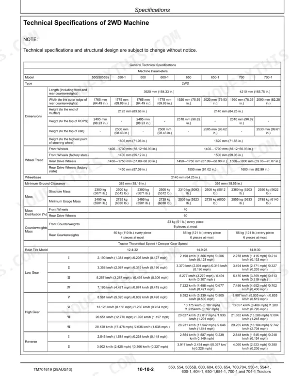
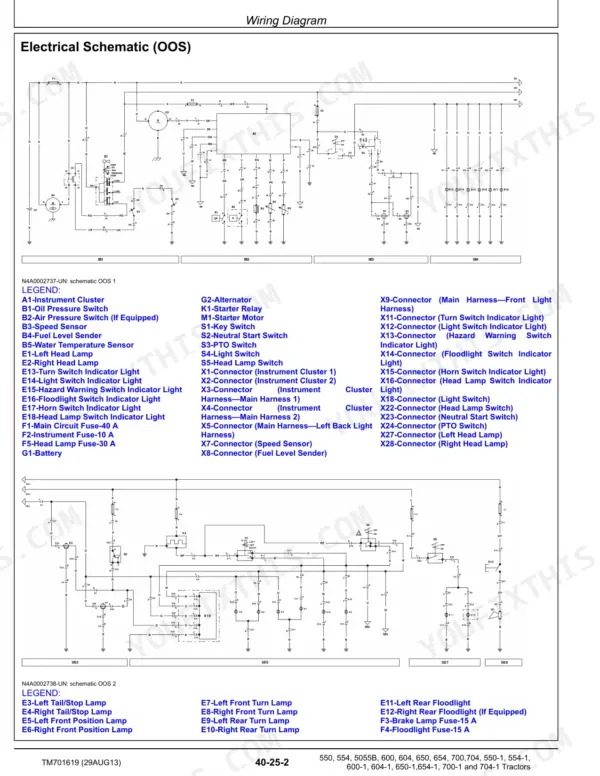
A slipping clutch or a rockshaft that won't hold a load can eat a week of fieldwork when the fault gets traced by trial and error. TM701619 is the 712-page John Deere technical manual PDF for the 550 through 704 tractor series, covering 17 variants including the 5055B. Power train repair fills about a third of the book, from clutch and PTO to transaxle, differential and final drives, while wiring diagrams trace your harness and hydraulic schematics map the pump, filter lines and rockshaft. During clutch work, set the lever to flywheel surface distance at 89-90 mm (3.50-3.54 in.); M12x1.5 steel hydraulic connectors take 21 N·m. One wrong guess costs you a clutch kit and a second tractor split. Bookmarked, text-searchable pages and exploded views of each assembly get your parts order right the first time, and the tractor back in the field before the weather turns.
What's Inside This John Deere 550–704 Series Tractors Manual
| System | Pages | Key Topics |
|---|---|---|
| General Information | 4-66 | Safety, Specifications, Fuel and Lubricants, Serial Number Locations, Drain Oil and Water Before Servicing |
| Engine | 67-78 | Engine Maintenance, Cooling System |
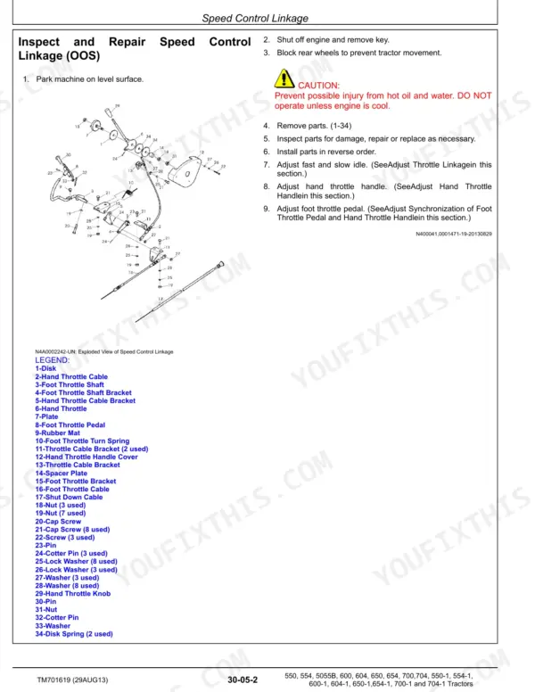
| Fuel and Air | 79-104 | Speed Control Linkage, Fuel System, Air Intake System |
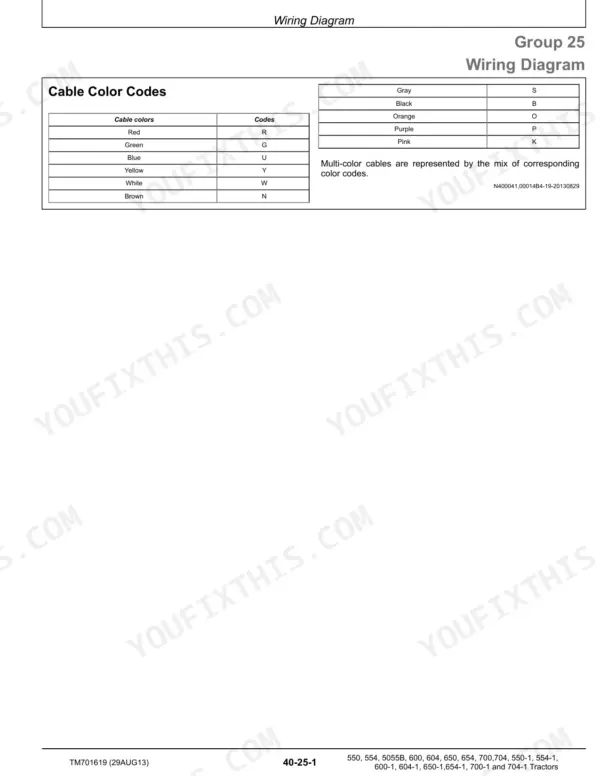
| Electrical System | 105-142 | Battery, Starter and Alternator, Electrical System Components, Wiring Harness |
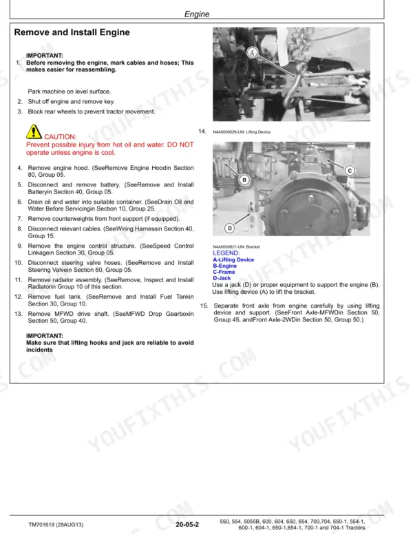
| Power Train | 143-380 | Component Removal, PTO, Clutch, Transaxle, Differential, Final Drives |
| Steering and Brakes | 381-414 | Steering Repair, Brake Repair, Air Brake |
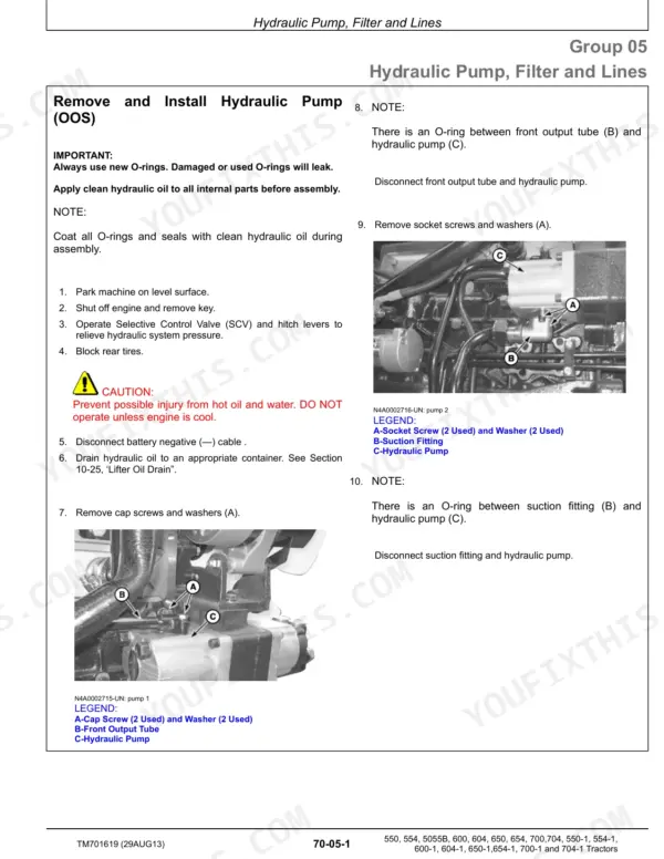
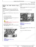
| Hydraulics | 415-440 | Hydraulic Pump, Filter and Lines, Rockshaft |
| Miscellaneous | 441-468 | Hood and Shields, Point Hitch |
| Cab Operator Station | 469-513 | Removal and Installation of Components (CAB), Removal and Installation of Components (OOS) |
| Special Tools (Dealer-Fabricated) | 514-519 | Dealer-Fabricated Tools |
| Operational Checkout Procedures | 520-533 | Engine Oil Level, Coolant Level, Transmission Oil, Hydraulic Oil, Fan and Belt, Fuel System, Air Intake System, Electrical System |
| Engine Operation Theory, Test and Adjust | 534-549 | Component Locations, Diagnose, Test, And Adjust |
| Fuel and Air System Operation Theory, Test, and Adjustment | 550-558 | Component Locations, Theory of Operation, Diagnose, Test, And Adjustments |
| Operational Principles, Test and Adjustment of Electrical System | 559-664 | Component Locations, Operational Principles, Diagnose, Test and Adjust |
| Operational Principles, Test and Adjustment of Drive System | 665-684 | Clutch Components, Gearbox Components, Final Drive Components, Rear PTO Components, Operational Principles of MFWD, Adjust Clutch |
| Operational Principles, Test and Adjustment of Steering and Braking Devices | 685-704 | 2WD Steering System Components, Brake System Components, Steering System Theory of Operation, Operational Principles of Braking System, Adjust Front Wheel Tread, Check Toe-In (MFWD) |
| Operational Principles, Test and Adjustment of Hydraulic System | 705-712 | Component Locations, Theory of Operation, Diagnose, Test and Adjust |
Quick Reference Specifications
| Specification | Value | Page |
|---|---|---|
| 550(5055B) | ||
| Maximum Torque | ≥193.7 N·m (143.1 lb-ft) | p. 31 |
| All Models | ||
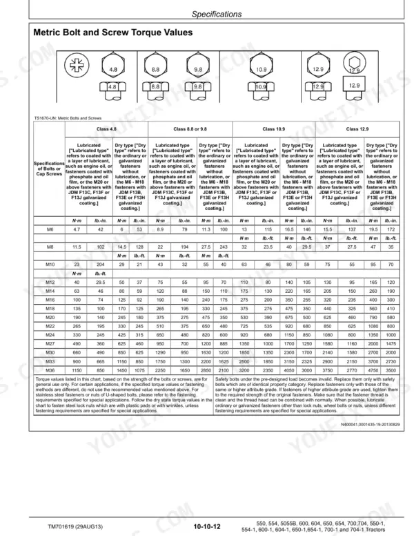
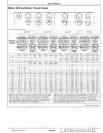
| Metric Bolt and Screw Torque Values (M6 Class 4.8 Lubricated) | 4.7 N·m | p. 40 |
| Hydraulic System Imperial Connector Torque (9/16-18 Guard Ring Nut) | 16 N·m | p. 42 |
| Hydraulic System Metric Connector Torque (M12x1.5 Steel or gray cast iron) | 21 N·m | p. 43 |
| Separate Lever (C) to Flywheel (A) Surface Distance (B) | 89-90 mm (3.50-3.54 in.) | p. 194 |
| Separate Lever (C) to Separate Bearing (E) Distance (D) | 2 mm (0.07 in.) | p. 194 |
| Brake Pedal Brake Distance | 70—90 mm (2.76—3.54 in.) | p. 402 |
| Brake Friction Disks Minimum Thickness | 4.15 mm (0.163 in.) | p. 402 |
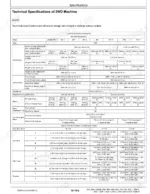
| Engine Rated Speed | 2300 rpm | p. 31 |
| Engine Minimum Speed without Load | 700 ± 30 rpm | p. 31 |
| Engine Maximum Speed without Load | ≤ 2484 rpm | p. 31 |
| 550, 554, 5055B, 600, 604, 650, 654, 700, 704, 550-1, 554-1, 600-1, 604-1, 650-1, 654-1, 700-1, 704-1 | ||
| Fuel Tank Capacity (CAB) | 110 L | p. 51 |
John Deere 550–704 Series Tractors Common Problems This Manual Covers
John Deere 550 clutch slips when engaged and does not fully separate with the pedal pressed down
Measure the separate lever to flywheel surface distance against 89-90 mm (3.50-3.54 in.) and the lever to separate bearing gap against 2 mm, both on page 194. Check the nut to clutch main disk distance at 1.45-1.55 mm. Then work the clutch slippage chart in the drive system diagnose section from page 665.
Manual Section: Operational Principles, Test and Adjustment of Drive System p. 665Brake pedal out of adjustment with excessive pedal travel before the brakes take hold
Adjust the brake pedal following the braking test and adjust procedures from page 685. Measure pedal brake distance against 70-90 mm (2.76-3.54 in.) listed on page 402. If travel will not come into spec, remove the brake assembly and measure the friction disks against the 4.15 mm (0.163 in.) minimum thickness. Torque brake assembly cap screws to 250-370 N·m.
Manual Section: Operational Principles, Test and Adjustment of Steering and Braking Devices p. 685Engine coolant temperature runs high during operation and the engine overheats under normal work
Check coolant level with the engine cold and fill toward the 13.4 L radiator capacity on page 39. Test fan belt tension on page 524: 29-39 N of force should deflect the belt 10-15 mm. Then work the coolant temperature high chart in the engine diagnose section from page 534 before heading back to the field.
Manual Section: Engine Operation Theory, Test and Adjust p. 534Rockshaft does not lift or lifts slowly and the hydraulic pump makes excessive noise
Check hydraulic oil level using the operational checkout from page 520 before touching anything else. Test pump pressure against the 16 MPa hydraulic system rated pressure on page 32. If pressure is low, work the insufficient pump delivery and rockshaft charts in the hydraulic diagnose section from page 705 so the three-point hitch is ready for the field.
Manual Section: Operational Principles, Test and Adjustment of Hydraulic System p. 705Steering hard to turn or fails to steer with oil leaking at the steering cylinder
Inspect the steering cylinder for leakage and repair it following the steering repair procedures starting on page 381. Test steering hydraulic pump output against its 10 MPa rated pressure on page 32. Torque the steering horizontal lever nut to 50 N·m (35 lb.-ft.), listed on page 401, during reassembly.
Manual Section: Operational Principles, Test and Adjustment of Steering and Braking Devices p. 685Engine low power with black smoke from the exhaust and difficult starting
Check engine speed first: low idle should hold 700 ± 30 rpm and no-load high idle should not exceed 2484 rpm, per page 31. Inspect the air intake system and air filter mounting, torquing the bracket cap screws to 55 N·m on page 100. Then follow the low power and black smoke charts from page 534.
Manual Section: Engine Operation Theory, Test and Adjust p. 534Frequently Asked Questions
What is the front wheel mounting nut torque spec for a 2WD John Deere 550, 554, 600, 604, 650, 654, 700 or 704 tractor?
The torque specification for the front wheel mounting nuts on a 2WD machine is 199–235 N·m (145–172 lb.-ft.). p. 462
What is the recommended oil for the transmission and hydraulic system?
John Deere HY-GARD or John Deere Low Viscosity Hy-Gard are the preferred oils for the transmission and hydraulic system. Other oils may be used if they meet JDM J20C or JDM J20D standards. p. 55
What is the procedure for bleeding the fuel system?
To bleed the fuel system, loosen the cap screw (A) at the fuel injection pump, operate the hand primer (B), and tighten the cap screw once the fuel flow is free from air bubbles. p. 99
What is the correct fan belt tension for the engine?
The fan and alternator belt should have a 10–15 mm deflection when a 29–39 N force is applied midway between the pulleys. p. 73
What is the torque spec for the engine and clutch housing mounting cap screws on a John Deere 550 to 704 tractor?
The torque specification for the engine and clutch housing mounting cap screws (M12) is 73–95 N·m (54–70 lb.-ft.). p. 68
Do I get instant access to this John Deere 550 Technical Manual?
Immediate download of the complete 712-page searchable Technical Manual. Access it on any device, from a laptop at your desk to a phone in the field.
Is this John Deere 550 manual print-friendly?
Yes. Print the sections you need to take out to the shop for your own use. Standard letter or A4 paper works.








Reviews
There are no reviews yet.