![John Deere 9540i 9560i 9580i 9640i 9660i 9680i and 9780i CTS Repair Manual [Combines]](https://youfixthis.com/wp-content/uploads/2012/02/Manual_Download-300x300.jpg)
Part of the John Deere Repair Manuals.
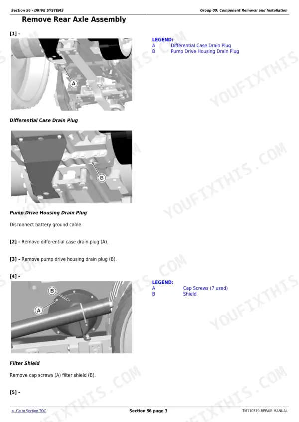
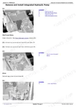
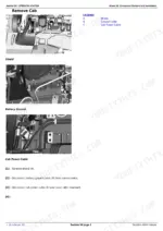
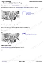
TM110519, the factory repair manual for John Deere 8310RT, 8335RT and 8360RT tracked tractors, serial range 902501-912000. This is the take-it-apart book: component removal and installation for the engine, PowerShift and AutoPowr/IVT transmissions, rear axle, final drives and PTO, steering and brakes, and the integrated hydraulic pump with hitch valve and selective control valves.
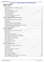
The undercarriage gets its own section - tracks, tension cylinder and accumulator, track frame and suspension. Torque figures are the real ones: front frame-to-transmission cap screws at 500 N·m (369 lb.-ft.), fan drive retaining nut at 400 N·m (295 lb.-ft.).
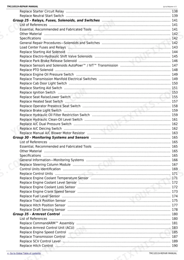
Electrical coverage means harness routings with numbered connectors, charging and starting circuits - not schematics. Dealer fabricated tools and the essential tool list close it out.
What's Inside This John Deere 8310RT, 8335RT, 8360RT Repair Manual
| System | Pages | Key Topics |
|---|---|---|
| General Information & Safety | 9-64 | Safety, General Information |
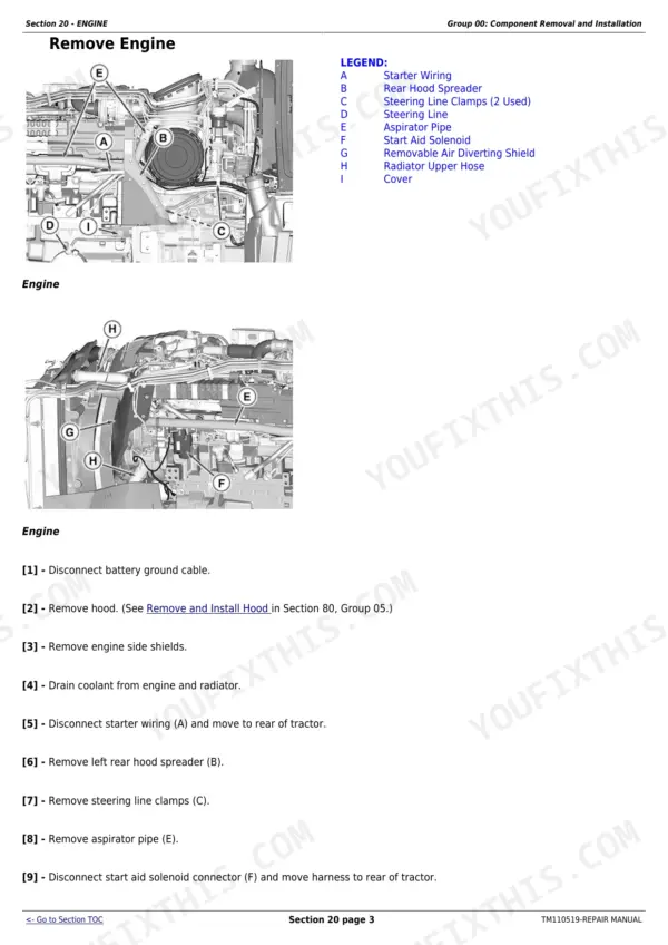
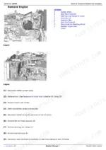
| Engine | 65-87 | Component Removal and Installation, Engine Repair |
| Fuel & Cooling Systems | 88-186 | Diesel Fuel System, Air Intake System, Engine Cooling System, Coolers and Air Conditioning Condenser, Exhaust System |
| Electrical System | 187-396 | Connectors, Wiring Harness Routings, Charging Circuit, Starting Circuit, Relays, Fuses, Solenoids, And Switches, Monitoring Systems and Sensors, Armrest Control, Implement and Accessory Connectors, Convenience and Accessory Components |
| PowerShift Transmission | 397-523 | Component Removal and Installation, Miscellaneous Repair, Transmission |
| AutoPowr/IVT Transmission | 524-715 | Component Removal and Installation, General Repair Procedures, In Tractor Repair, Transmission Repair, Assemble Transmission |
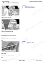
| Drive Systems | 716-878 | Component Removal and Installation, Rear Axle Assembly, Final Drives, PTO, Steering Gears, Mid-Frame Drive Shafts |
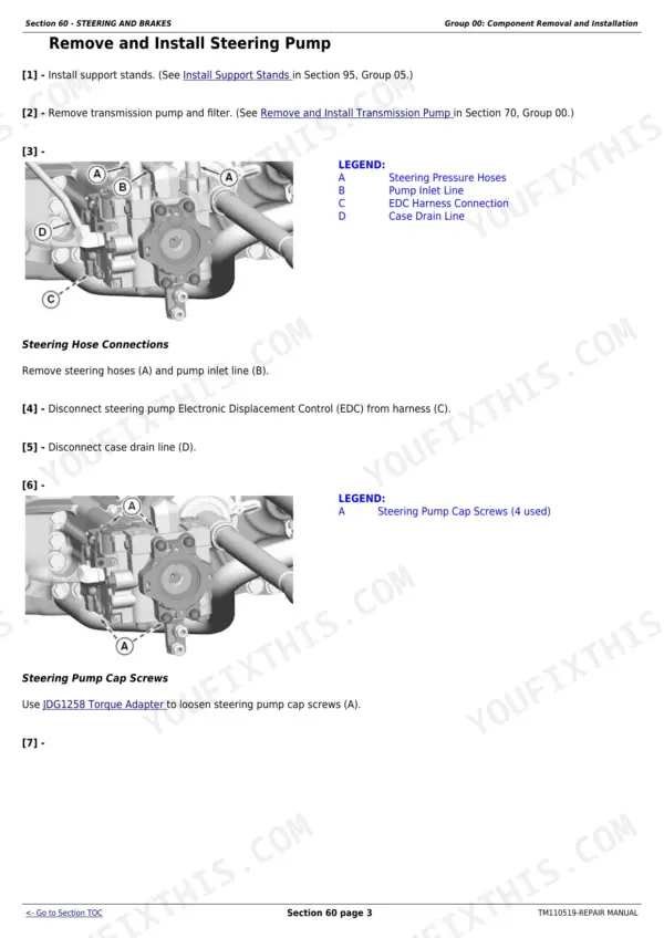
| Steering & Brakes | 879-1015 | Component Removal and Installation, Steering Column, Steering Wheel Position Input Assembly, Steering Pump, Brakes, Hydraulic Trailer Brake |
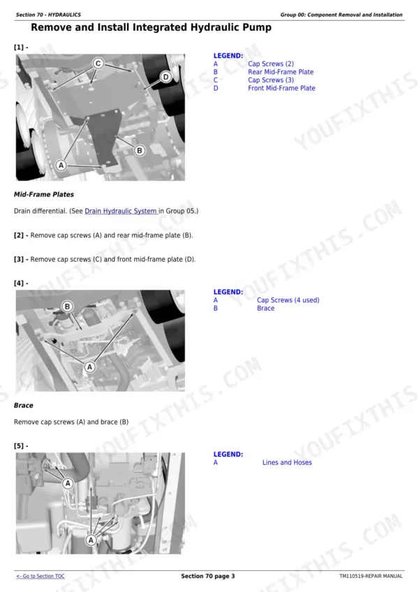
| Hydraulic System | 1016-1114 | Component Removal and Installation, Hydraulic System Repair and Cleanup, Integrated Hydraulic Pump, Hitch Valve, Selective Control Valves, And Couplers, Hitch |
| Hood & Platform | 1115-1128 | Hood, Platform Step Assembly |
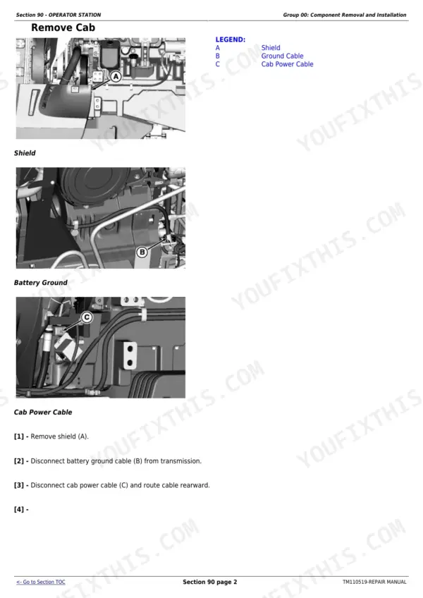
| Operator Station & HVAC | 1129-1219 | Component Removal and Installation, Heating, Ventilating, And Air Conditioning (HVAC), Air Conditioning System, Air Suspension Seat, Armrest, Cab Door and Windshield |
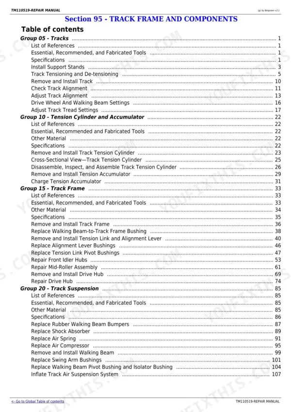
| Track Frame & Suspension | 1220-1331 | Tracks, Tension Cylinder and Accumulator, Track Frame, Track Suspension |
| Dealer & Fabricated Tools | 1332-1432 | Dealer Fabricated Tools, Essential and Recommended Tools |
Quick Reference Specifications
| Specification | Value | Page |
|---|---|---|
| Engine-to-Transmission Drive Shaft Cap Screws | 126 N·m (92 lb.-ft.) | p. 66 |
| Front Frame-to-Transmission Cap Screws | 500 N·m (369 lb.-ft.) | p. 66 |
| Front Support-to-Front Frame Cap Screws | 430 N·m (317 lb.-ft.) | p. 66 |
| Oil Pan Cap Screws (1-8, 11, 12), torque-turn | 50 N·m + 60° turn (37 lb.-ft. + 60°) | p. 66 |
| Inertia Ring / Dampener-to-Flywheel Cap Screws | 70 N·m (52 lb.-ft.) | p. 81 |
| Transmission Drive Hub-to-Flywheel Dampener Cap Screws | 126 N·m (92 lb.-ft.) | p. 81 |
| Damper and Inertia Ring Weight | 38 kg (83 lb.) | p. 83 |
| Air Intake Flange Clamps | 20 N·m (178 lb.-in.) | p. 97 |
| Thermostat Cover Cap Screws | 48 N·m (35 lb.-ft.) | p. 105 |
| Radiator Pressure Test | 90 kPa (0.9 bar / 13 psi) | p. 105 |
| Radiator Cap Pressure Test | 103 kPa (1.03 bar / 15 psi) | p. 105 |
| Fan Drive Gear Cap Screw | 150 N·m (111 lb.-ft.) | p. 106 |
| Fan Drive Retaining Nut | 400 N·m (295 lb.-ft.) | p. 106 |
John Deere 8310RT, 8335RT, 8360RT Common Problems This Manual Covers
Track tension keeps dropping, or a track walks off under side load on slopes.
Start with the tension cylinder and accumulator group in the Track Frame and Suspension section. It covers removal and installation of the tension cylinder and accumulator, plus track removal, track frame and track suspension repair, so you fix the cause instead of just cranking tension back in.
Manual Section: Track Frame & Suspension p. 1241AutoPowr/IVT trouble - harsh engagement, loss of drive, or a rebuild coming due.
The AutoPowr/IVT Transmission section is the deepest in the book: general repair procedures, an in-tractor repair group for jobs that do not require splitting the tractor, full transmission repair, and an assemble-transmission group that walks the unit back together in order.
Manual Section: AutoPowr/IVT Transmission p. 524Weak or slow hydraulics, hitch drifting down, or a selective control valve that leaks.
Go to the Hydraulic System section: integrated hydraulic pump removal and repair, the hitch valve, selective control valves and couplers, and the hitch itself. There is also a hydraulic system repair and cleanup group, which matters after a pump failure puts debris through the circuit.
Manual Section: Hydraulic System p. 1060Cab air conditioning quits in the middle of summer fieldwork.
The Operator Station and HVAC section carries component removal and installation for the heating, ventilating and air conditioning system plus the air conditioning system itself; the condenser is handled with the coolers in the Fuel and Cooling Systems section. Seat, armrest, cab door and windshield work sits alongside it.
Manual Section: Operator Station & HVAC p. 1165Frequently Asked Questions
Does it cover the tracks and undercarriage, or just the tractor on top of them?
Full coverage, and it is the reason to buy the RT-specific book instead of a wheeled 8R manual. The Track Frame and Suspension section handles track removal and installation, the tension cylinder and accumulator, the track frame, and the track suspension. On a machine that lives or dies by its undercarriage, this is the section that pays for the manual. p. 1220
My tractor has the AutoPowr/IVT. Can I actually repair it with this manual, or does it just say replace the unit?
You can repair it. The AutoPowr/IVT gets its own section with component removal and installation, general repair procedures, an in-tractor repair group for work that does not require pulling the transmission, full transmission repair, and a dedicated assemble-transmission group. The PowerShift option is covered too, in a separate section with its own removal, repair and miscellaneous repair procedures. p. 524
Are there wiring diagrams or hydraulic schematics in this manual?
No schematics. What the electrical section does carry is wiring harness routings (Section 40 Group 10) with numbered connectors, plus groups on connectors, the charging circuit, starting circuit, relays, fuses, solenoids and switches, and the monitoring system and sensors. That is enough to physically trace, unpin and repair a harness. If you specifically need circuit schematics, know that before you buy. p. 250
Do the repair jobs call for special tools I would have to buy from Deere?
Some do, and the manual is honest about it. There is a section listing essential and recommended tools, and a Dealer Fabricated Tools group for the ones a shop can make itself. Big jobs also lean on ordinary equipment and correct torques - the book gives figures like 500 N·m (369 lb.-ft.) for the front frame-to-transmission cap screws, so nothing is left to feel. p. 1361
Will it fit my 2015 8360RT?
Check your serial number plate, not the calendar. This is publication TM110519 and it covers 8310RT, 8335RT and 8360RT tracked tractors in serial range 902501-912000. If your serial falls in that range, this is your book. p. 9