
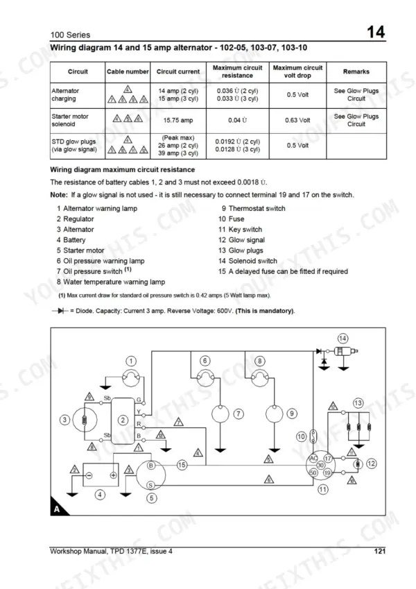
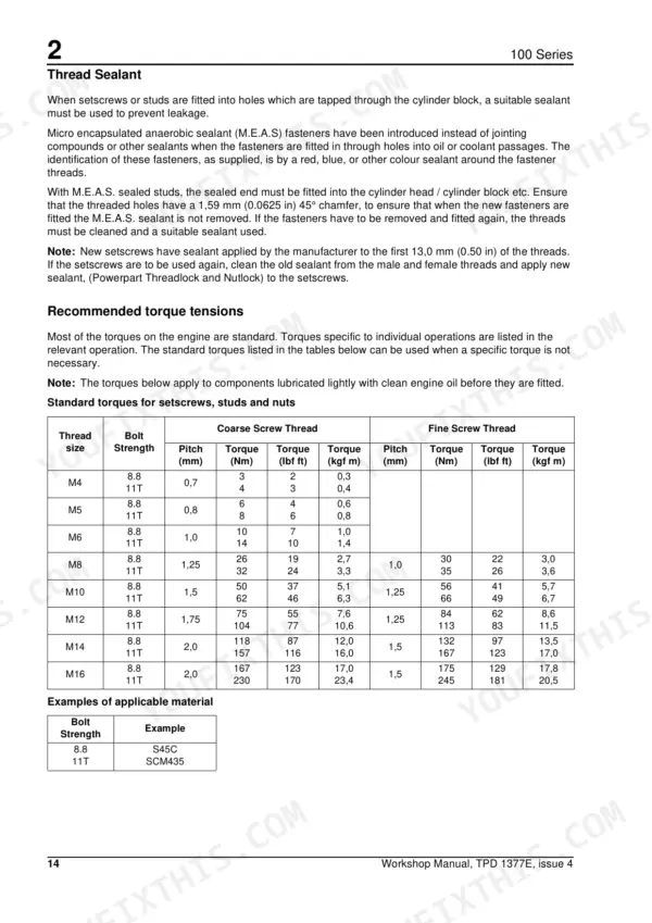
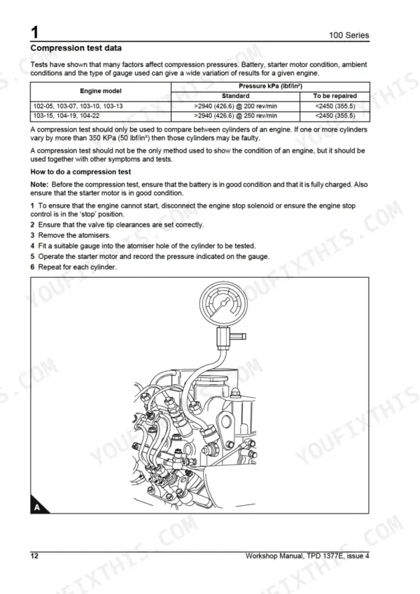
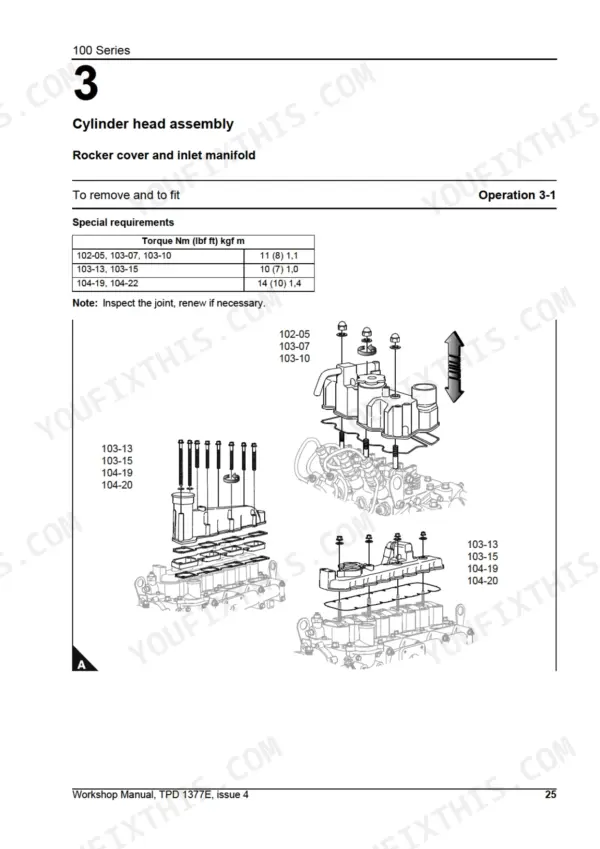
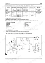
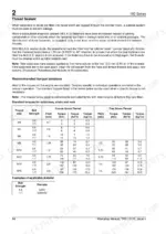
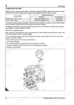
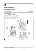
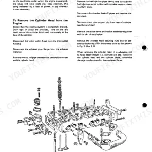
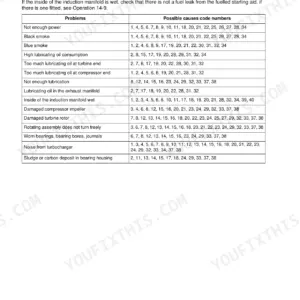
Need the factory book for your Perkins 100 Series diesel? This 144-page Perkins 100 Workshop Manual PDF (OEM TPD 1377E) covers the 102-05, 103-07, 103-10, 103-13, 103-15, 104-19, and 104-22 engines, from cylinder head to crankshaft. You get factory wiring diagrams for the alternator, starter motor, and auto-shutdown circuits, plus a full specifications section: torque tensions, cylinder bore dimensions, injection timing, and undersize bearing charts. Step-by-step procedures walk you through the fuel injection pump, timing case, pistons, and coolant pump. Head bolt torque matters here: 37 Nm on the 102-05 and 103-07 but 100 Nm on the 104-22, and the tables call out every variant. Seat the glowplugs at 17 Nm. No more guessing which spec fits which engine. Bookmarked with a live text layer, so you can jump straight to injection pump timing right from your phone in the shop.
What's Inside This Perkins 100 Series (102–104) Manual
| System | Pages | Key Topics |
|---|---|---|
| General Information | 11-22 | Introduction, Safety Precautions, Engine Preservation, Powerpart Recommended Consumable Products, Engine I.D. Location, Engine Views - 3 Cylinder Front and Rear |
| Specifications | 23-34 | Basic Engine Data, Thread Sealant, Recommended Torque Tensions, Data and Dimensions, Injection Timing, Cylinder Bore Dimensions, Piston and Piston Ring Dimensions, Gudgeon Pin |
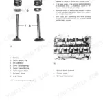
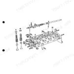
| Cylinder Head Assembly | 35-58 | Rocker Cover and Inlet Manifold, Rocker Assembly, Rocker Shaft, Fan and Mounting, Exhaust Manifold and Gasket, Fuel Injection Pipes / Fuel Return Pipes, Oil Pipes, Atomisers |
| Piston and Connecting Rod Assemblies | 59-66 | Big End Bearing and Cap, Piston and Connecting Rod, Piston and Piston Ring, Piston Ring and Block, Small End Bush, Connecting Rod |
| Crankshaft Assembly | 67-74 | Crankshaft Pulley, Flywheel, Backplate and Oil Seal, Crankshaft Retainer Setscrews and Crankshaft, Bearing Clearance, Main Bearings |
| Timing Case and Drive Assembly | 75-92 | Fuel Injection Pump, Timing Cover, Slider, Camshaft Retainer Plate, Camshaft and Cam Followers, Camshaft Assembly, Max Fuel Screw and Max Speed Screw, Idler Gear and Oil Pump |
| Cylinder Block Assembly | 93-94 | Front Bush, Cylinder Block Top Face |
| Engine Timing | 95-98 | Fuel Injection Pump Timing |
| Aspiration System | 99-100 | Breather System |
| Lubrication System | 101-106 | Oil Filter Canister, Pressure Relief Valve, Lubricating Oil Sump, Strainer and Suction Pipe, Lubricating Oil Pump, Oil Pressure Switch |
| Fuel System | 107-114 | Atomisers, Fuel Lift Pump, Fuel Injection Pump, Vent Points |
| Cooling System | 115-120 | Fan and Mounting, Coolant Pump, Thermostat |
| Flywheel and Housing | 121-124 | Flywheel, Flywheel Housing |
| Electrical Equipment | 125-140 | Electrical Shut Off Solenoid, Alternator, Starter Motor (Wiring Diagrams, Auto Shutdown Wiring Diagrams) |
| Auxiliary Equipment | 141-142 | Radiator Anti-Vibration Mountings |
| Special Tools | 143-144 | Special Tools List |
Quick Reference Specifications
| Specification | Value | Page |
|---|---|---|
| 102-05, 103-07, 103-10 | ||
| Rocker cover and inlet manifold torque | 11 Nm (8 lbf ft) 1.1 kgf m | p. 35 |
| 102-05, 103-07, 103-10, 103-13, 103-15 | ||
| Rocker assembly torque | 23 Nm (17 lbf ft) 2.3 kgf m | p. 36 |
| All Models | ||
| Torque for Glowplugs | 17 Nm (12 lbf ft) 1,7 kgf m | p. 44 |
| Torque for fuel injection pipes 102-05, 103-07, 103-10 | 22 Nm (16 lbf ft) 2,2 kgf m | p. 41 |
| Torque for fuel injection pipes 103-13, 103-15, 104-19, 104-22 | 20 Nm (15 lbf ft) 2,0 kgf m | p. 41 |
| Valve tip clearance (cold) | 0.2 mm | p. 23 |
| Oil pressure switch operating range | 19.3-39.3 KPa | p. 106 |
| 102-05, 103-07, 103-10, 103-13, 103-15, 104-19 | ||
| Oil pressure relief valve pressure (102-05, 103-07, 103-10, 103-13, 103-15, 104-19) | 262-359 KPa | p. 23 |
| 104-22 | ||
| Oil pressure relief valve pressure, 104-22 | 352-448 KPa | p. 23 |
| 102-05, 103-07 | ||
| Fan belt deflection (102-05, 103-07) | 4 mm | p. 115 |
| 103-10 | ||
| Fan belt deflection, 103-10 | 5 mm | p. 115 |
| 103-13, 103-15, 104-19 | ||
| Fan belt deflection (103-13, 103-15, 104-19) | 6 mm | p. 115 |
Perkins 100 Series (102–104) Common Problems This Manual Covers
Perkins 100 Series diesel cranks but will not fire after fuel filter change or running the tank dry
Bleed the fuel system at the vent points covered on page 107. Slacken each vent screw, work the lift pump priming lever until fuel flows free of bubbles, then tighten. If the glow plugs came out during service, refit and torque them to 17 Nm (12 lbf ft) before trying another cold start.
Manual Section: Fuel System p. 107Low oil pressure warning light stays on at idle after an oil and filter change
Check the sump level and top up before anything else. Verify the oil pressure switch against its operating range of 19.3-39.3 kPa on page 106, since a lazy switch mimics a worn pump. If pressure is genuinely low, drop the sump and clean the strainer and suction pipe per the lubrication procedures starting on page 101.
Manual Section: Lubrication System p. 101Engine runs hot and pushes coolant out of the radiator under load, temperature gauge climbing steadily
Test the thermostat in heated water before condemning the coolant pump. On 102-05 and 103-07 engines it should start to open at 73-77 degrees C per the data on page 119; replace it if it sticks or opens late. Check fan belt tension and inspect the coolant pump for seal weep using the cooling system section on page 115.
Manual Section: Cooling System p. 115Heavy oil mist from the crankcase breather and oil consumption climbing between service intervals
Check the breather pipe for blockage first using the aspiration system section on page 99; a plugged pipe fakes worn rings. Set valve tip clearance to 0.2 mm cold and run a compression check. If compression stays low, pull the pistons and measure ring gaps against the data in the piston section starting on page 59.
Manual Section: Aspiration System p. 99Battery goes flat overnight, cranking speed dropping a little more each cold morning
Test charging voltage with the engine running: it must sit between 13.6 and 14.7 volts per the procedure on page 127, and outside that range the alternator is faulty. Before condemning anything, clean and tighten the battery terminals and ground straps, since a bad connection drags cranking speed down long before the battery dies.
Manual Section: Electrical Equipment p. 127Frequently Asked Questions
How do I bleed the fuel system after a shutdown?
To vent the fuel system, loosen the vent screw on the fuel filter and operate the hand primer on the lift pump until air-free fuel flows. Then, loosen the vent screw on the fuel injection pump and repeat the priming process. Finally, loosen all fuel pipes at the atomiser end and operate the starter motor until fuel flows from the pipes before tightening them. p. 114
What are the torque specifications for the cylinder head bolts?
The torque specifications for the cylinder head bolts vary by engine model. For 102-05 and 103-07 models, the torque is 37 Nm (27 lbf ft). For 103-10 models, it is 51 Nm (38 lbf ft), and for 103-13, 103-15, 104-19, and 104-22 models, it is 100 Nm (74 lbf ft). p. 48
What is the correct valve tip clearance for the engine?
The valve tip clearance for both the inlet and exhaust valves should be set to 0.2 mm (0.0078 in) when the engine is cold. p. 23
What is the correct fan belt deflection for the 102-05 and 103-07 engines?
For the 102-05 and 103-07 engine models, the fan belt deflection should be approximately 4 mm when depressed at the center between the crankshaft and alternator pulleys with a finger force of 49 N (11 lbf). p. 115
What is the oil pressure relief valve torque setting?
The torque setting for the pressure relief valve is 64 Nm (47 lbf ft). p. 102
Is this Perkins 100 manual a download or a disc?
Delivery is instant: a 144-page searchable PDF is yours the second checkout clears. Laptop, tablet, or phone, all fine.
Is this Perkins 100 Workshop Manual printable?
Yes. Printing works from any reader and any printer, for your own shop use.
Reviews
There are no reviews yet.