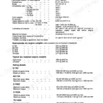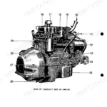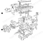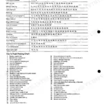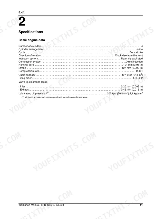
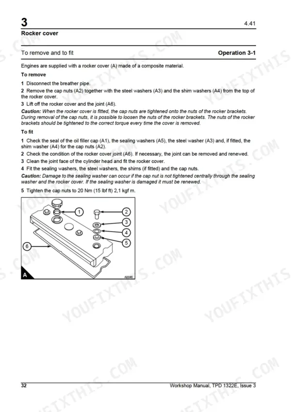
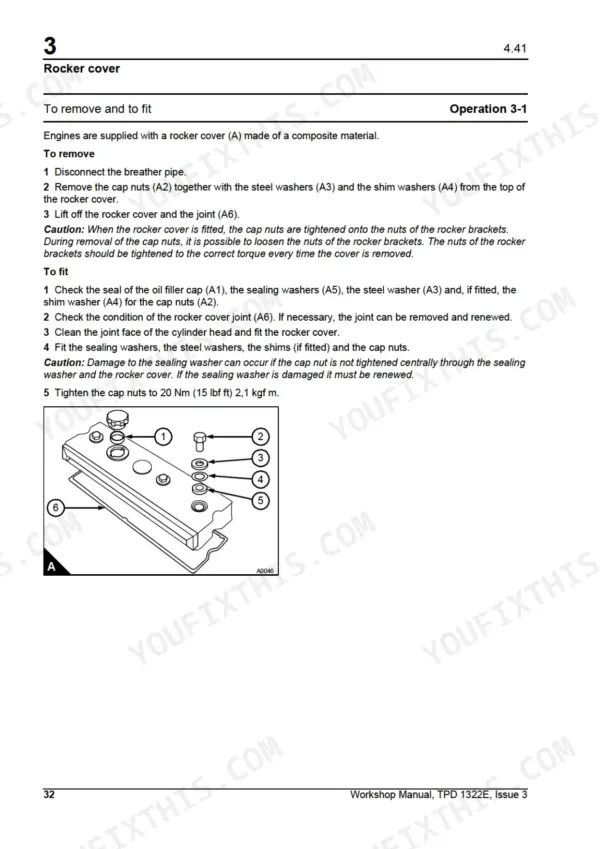


Rebuilding a Perkins 4.41? This 212-page Model LM Shop Manual PDF (OEM #TPD 1322E) covers the complete diesel engine, cylinder head to flywheel housing. Inside: factory torque settings, compression test data, lubrication flow diagrams for the relief valve and balancer unit, and full step-by-step procedures for the crankshaft, pistons, timing case, and cylinder block. You also get injection pump timing for both Lucas DPA and Stanadyne pumps, plus an alternator fault diagnosis section for chasing charging problems. Set the inlet valve tip clearance to 0.20 mm cold, the exhaust to 0.45 mm, then pull the cylinder head setscrews down with the final 150-degree turn the factory calls for. Forum threads won't rebuild your bottom end. This PDF is bookmarked and keyword-searchable; load it on your phone or laptop, find the spec, and get back to the engine.
What's Inside This Manual
| System | Pages | Key Topics |
|---|---|---|
| General Information | 13-22 | Introduction, Engine Views, Engine Identification, Safety Precautions, Engine Lift Equipment, Viton Seals, Powerpart Recommended Consumable Products |
| Specifications | 23-42 | Basic Engine Data, Data and Dimensions, Recommended Torque Settings, Compression Test Data |
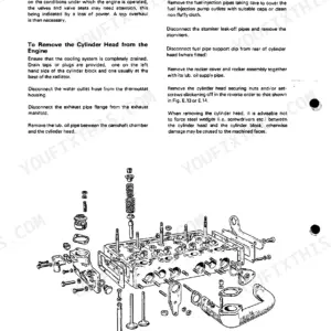
| Cylinder Head Assembly | 43-64 | Rocker Assembly, Cylinder Head |
| Piston and Connecting Rod Assemblies | 65-76 | Big End Bearing, Piston and Connecting Rod, Piston Rings, Piston and Connecting Rod Assembly, Piston and Piston Rings, Connecting Rod, Small End Bush |
| Crankshaft Assembly | 77-100 | Crankshaft Pulley, Rear Oil Seal Assembly, Thrust Washers, Main Bearings, Crankshaft, Balancer Unit |
| Timing Case and Drive Assembly | 101-118 | Timing Case Cover, Front Oil Seal, Idler Gear and Hub, Fuel Pump Gear, Camshaft Gear, Crankshaft Gear, Timing Case, Camshaft and Tappets |
| Cylinder Block Assembly | 119-128 | Cylinder Block, Cylinder Liner |
| Engine Timing | 129-140 | Lucas Dpa Fuel Injection Pumps, Stanadyne Fuel Injection Pumps |
| Aspiration System | 141-142 | Open Engine Breather |
| Lubrication System | 143-156 | Lubrication System Flow Diagram, Lubrication System Flow Diagram for the Relief Valve and Balancer, Filter Canister, Filter Head, Sump, Oil Strainer and Suction Pipe |
| Fuel System | 157-178 | Fuel Filter Element, Atomisers, Fuel Lift Pump, Lucas Dpa Fuel Injection Pump, Stanadyne Fuel Injection Pump |
| Cooling System | 179-188 | Thermostats, Coolant Pump, Fan, Lubricating Oil Cooler |
| Flywheel and Flywheel Housing | 189-192 | Flywheel, Ring Gear, Flywheel Housing |
| Electrical Equipment | 193-202 | Alternators, Alternator Fault Diagnosis, Starter Motors, Starting Aid |
| Auxiliary Equipment | 203-206 | Power Take-Off Adaptors, Exhauster |
| Special Tools | 207-212 | List of Special Tools |
Quick Reference Specifications
| Specification | Value | Page |
|---|---|---|
| Inlet valve tip clearance (cold) | 0,20 mm (0.008 in) | p. 23 |
| Exhaust valve tip clearance (cold) | 0,45 mm (0.018 in) | p. 23 |
| Width of third ring | 4,98/4,99 mm (0.1960/0.1964 in) | p. 29 |
| Minimum valve lift, fully open | 9 mm (0.35 in) | p. 26 |
| Short cylinder head setscrews (S) additional turn | 150° (2.5 flats) | p. 53 |
| Long cylinder head setscrews (L) additional turn | 210° (3.5 flats) | p. 53 |
| Oil pump idler gear backlash | 0.076 mm | p. 152 |
| Oil pump idler gear end-float | 0.012/0.643 mm | p. 152 |
| Fuel lift pump setscrew torque | 22 Nm (16 lbf ft) | p. 152 |
| Minimum lubricating oil pressure | 207 kPa | p. 23 |
| Cylinder head setscrew torque (initial) | 110 Nm | p. 53 |
| Alternator drive belt deflection | 10 mm | p. 194 |