
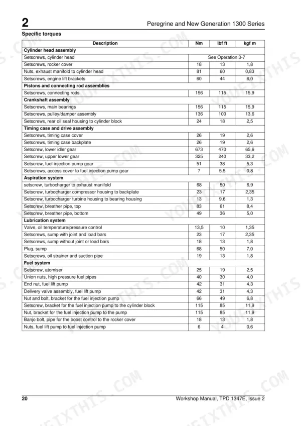
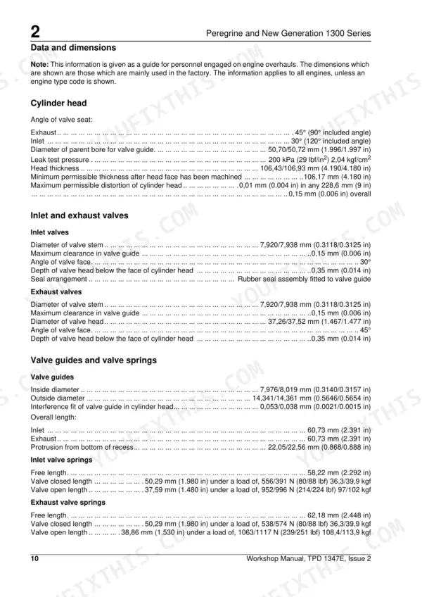
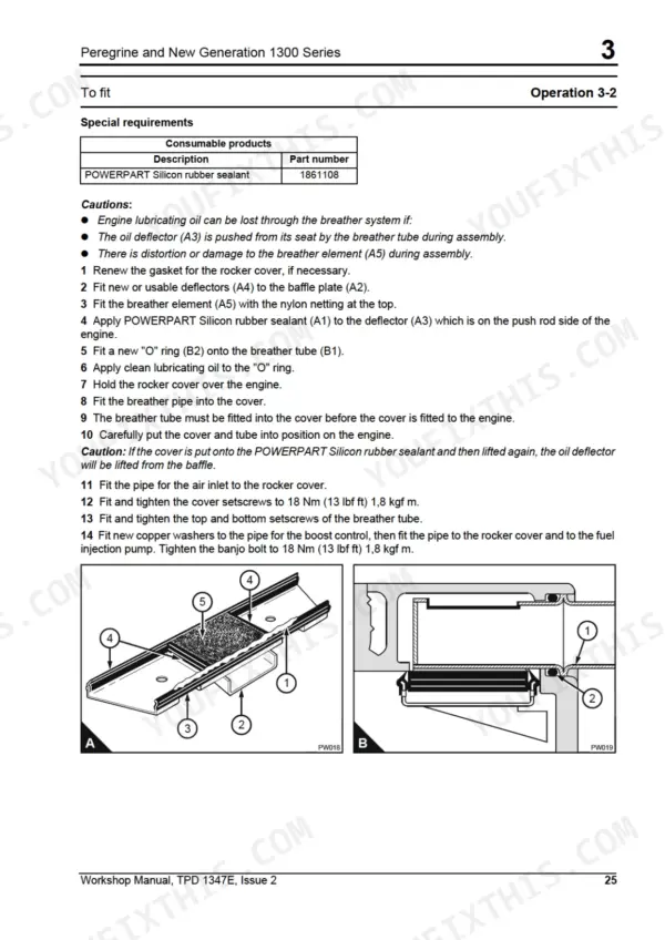
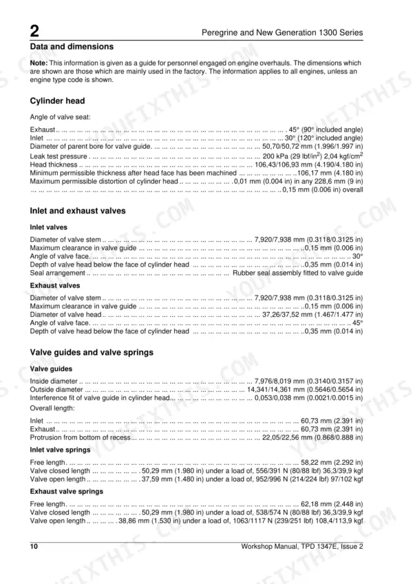
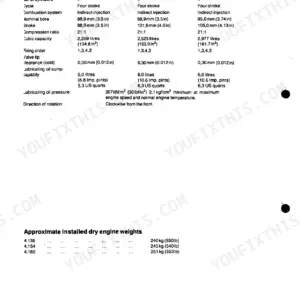
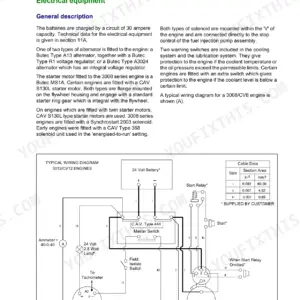
Every one of the 198 pages in this Perkins 1300 shop manual PDF (OEM TPD 1347E) is factory teardown data for the Peregrine and 1300 Series diesel engines: WD, WE, WF, WG, WH, and WJ builds. Inside: a full recommended torque settings section, static timing charts, turbocharger waste-gate adjustment procedures, and step-by-step cylinder head, crankshaft, and fuel injection pump work. You also get alternator fault diagnosis plus lubrication and cooling system flow diagrams. Bore runs 109.2 mm on WD through WG engines and 116.5 mm on WH and WJ; torque the fuel lift pump nuts to 6 Nm before you bleed the fuel system. Your engine is on the stand and the clock is running. Bookmarked with a live text layer; type the spec you need and jump straight to it.
What's Inside This Perkins 1300 Series Peregrine (WD–WJ) Manual
| System | Pages | Key Topics |
|---|---|---|
| General Information | 1-18 | Introduction, Engine Identification, Safety Precautions, Engine Lift Equipment, Powerpart Recommended Consumable Products |
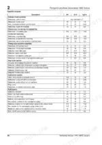
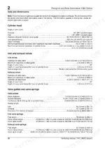
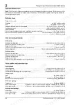
| Specifications | 19-32 | Basic Engine Data, Data and Dimensions, Recommended Torque Settings |
| Cylinder Head Assembly | 33-58 | Rocker Cover (Remove, Fit), Rocker Assembly (Remove, Dismantle and Inspect, Assemble), Cylinder Head (Remove |
| Piston and Connecting Rod Assemblies | 59-70 | Big End Bearing (Remove, Fit, Inspect), Piston and Connecting Rod Assembly (Remove, Dismantle and Assemble, Connecting Rod (to Inspect) |
| Crankshaft Assembly | 71-90 | Crankshaft Pulley/Damper Assembly (Remove, Fit, Inspect) |
| Timing Case and Drive Assembly | 91-106 | Components of the Timing Case, Timing Case Cover (Remove, Fit), Idler Gears (Remove, Fuel Injection Pump Gear (to Remove and to Fit), Timing Case Backplate (Remove |
| Cylinder Block Assembly | 107-114 | Cylinder Block (Dismantle and to Assemble, Inspect), Cylinder Liner (Remove, Fit |
| Engine Timing | 115-120 | Static Timing Chart |
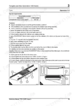
| Aspiration System | 121-132 | Turbocharger (Remove, Fit, Dismantle, Assemble, Inspect, Clean the Impeller and Compressor Casing, Remove and to Fit the Actuator Assembly of the Waste-Gate Unit, Check and to Adjust the Actuator Assembly of the Waste-Gate Unit) |
| Lubrication System | 133-154 | Lubrication System Flow Diagram, Filter Canister (to Renew the Canister of the Lubricating Oil Filter), Filter Head and Oil Cooler Assembly (Remove, Fit, Inspect) |
| Fuel System | 155-168 | Fuel Filter (Fuel Pre-Filter, To Renew the Fuel Strainer and the Canister of the Fuel Filter), Atomiser (Fault, To Renew an Atomiser) |
| Cooling System | 169-176 | Cooling System Flow Diagram, Filter Canister (to Renew the Canister of the Coolant Filter/ Inhibitor), Thermostat (Remove and to Fit, Test), Coolant Pump (to Remove and to Fit) |
| Flywheel and Housing | 177-180 | Flywheel (to Remove and to Fit), Ring Gear (to Remove and to Fit), Flywheel Housing (to Remove and to Fit) |
| Electrical Equipment | 181-190 | Alternators (Remove and to Fit, Maintain), Alternator Fault Diagnosis, Starter Motors (Remove and to Fit, Maintain, Test on the Engine) |
| Auxiliary Equipment | 191-194 | Compressors (to Remove and to Fit), Power Steering Pump (to Remove and to Fit) |
| Special Tools | 195-198 | List of Special Tools |
Quick Reference Specifications
| Specification | Value | Page |
|---|---|---|
| All Models | ||
| Minimum lift equipment capacity | 770 Kg (1700 lbs) | p. 16 |
| Nuts, fuel lift pump to fuel injection pump torque | 6 Nm (4 lbf ft) | p. 20 |
| Lucas S115, Lucas PE129, Delco 37 MT or Delco 42 MT ratings | 12V/4.25kW or 24V/6kW (Lucas), 12V or 24V (Delco) | p. 28 |
| Cylinder head leak test pressure | 200 kPa | p. 20 |
| Inlet valve stem diameter | 7.920/7.938 mm | p. 20 |
| Exhaust valve stem diameter | 7.920/7.938 mm | p. 20 |
| Cylinder head setscrew torque (final) | 225 Nm | p. 42 |
| Lubricating oil pump operating pressure | 345 kPa | p. 26 |
| Thermostat fully open temperature | 94 °C | p. 27 |
| WD, WE, WF, WG | ||
| Bore (WD, WE, WF, WG) | 109.2 mm | p. 19 |
| WH, WJ | ||
| Bore (WH, WJ) | 116.5 mm | p. 19 |
Perkins 1300 Series Peregrine (WD–WJ) Common Problems This Manual Covers
Perkins 1300 Peregrine cranks but will not start, slow cranking speed in cold weather
Measure battery voltage and load-test before condemning the starter; clean and tighten every ground strap and battery cable. Verify the starter rating against the spec on page 28: Lucas units are 12V/4.25kW or 24V/6kW. If cranking speed is good but it still won't fire, bleed the fuel system and check the lift pump for air ingress.
Manual Section: Electrical Equipment p. 28Engine starts then runs rough or stalls, worse after a fuel filter change
Bleed the low-pressure fuel system completely and inspect every fitting from tank to lift pump; a weeping connection sucks air without ever dripping fuel. Renew the fuel strainer and filter canister following the Fuel System section starting on page 155, then torque the lift pump nuts at the injection pump to 6 Nm (4 lbf ft) and recheck after a test run.
Manual Section: Fuel System p. 155Engine overheating at working RPM, coolant temperature keeps climbing, no visible external leaks
Check coolant level and clear debris from the radiator core before blaming the pump. Test the thermostat in heated water; it must be fully open at 94 C, the spec listed on page 27. Inspect the coolant pump and belt tension using the Cooling System procedures beginning on page 169, and renew the coolant filter/inhibitor canister while the system is drained.
Manual Section: Cooling System p. 169Low oil pressure warning at hot idle, oil level and condition look correct
Verify the oil grade matches operating temperature before pulling anything apart; wrong viscosity mimics a worn pump. Fit a mechanical gauge and compare readings against the pump operating pressure of 345 kPa listed on page 26. If pressure stays low with correct oil, inspect the filter head and oil cooler assembly per the Lubrication System section starting on page 133.
Manual Section: Lubrication System p. 133White exhaust smoke with steady coolant loss, overflow bottle bubbles under load
Remove the cylinder head and check for cracks and distortion following the Cylinder Head Assembly section starting on page 33. Pressure test the head at 200 kPa to confirm internal leakage before machining or replacing it. On reassembly, follow the tightening sequence and torque the head setscrews to a final 225 Nm.
Manual Section: Cylinder Head Assembly p. 33Frequently Asked Questions
How do I eliminate air from the fuel system on a Perkins 1300 Series engine?
To eliminate air, loosen the vent plug on the top of the fuel filter head. Operate the plunger of the fuel priming pump until fuel, free from air, comes from the filter vent point, then tighten the vent plug. If the engine runs roughly or stops, check for leaks in the low-pressure system. p. 168
What is the correct torque setting for the cylinder head setscrews?
The cylinder head setscrews must be tightened in three stages using the sequence shown in the manual. The final torque is 225 Nm (165 lbf ft) 23 kgf m. p. 42
What is the valve tip clearance for the inlet and exhaust valves?
The correct valve tip clearance for both inlet and exhaust valves is 0,64 mm (0.025 in) when the engine is hot or cold. p. 56
What is the procedure for tightening the main bearing cap setscrews?
The main bearing cap setscrews must be tightened gradually and evenly to 155 Nm (115 lbf ft) 16,0 kgf m. p. 82
What is the operating pressure of the oil pressure regulator valve?
The oil pressure regulator valve operates at 345 kPa (50 lbf/in2) 3,51 kgf/cm2. p. 26
How is this Perkins Peregrine Shop Manual delivered?
You download the Shop Manual yourself: 198 pages, searchable PDF, available immediately. Keep a copy on every device you use.
Can I print just the pages I need from this Perkins Peregrine manual?
Printing is allowed without restriction. Pull the pages you need for the job and bin them when they get greasy.
Reviews
There are no reviews yet.