
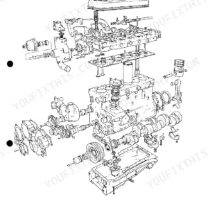
Rebuilding a Perkins 4.236? This Perkins A4.236 workshop manual PDF (OEM #601 TPD 0393 1229) packs 168 pages covering the whole four-cylinder family: 4.2482, 4.248, 4.236, 4.212, T4.236, T4.38, A4.248, A4.236, and AT4.236. Inside you get factory torque and clearance tables, a fault diagnosis chart, and page after page of exploded views walking you through cylinder head, crankshaft, balancer unit, timing case, fuel system, and turbocharger work, with a full marine supplement at the back. Check the injection pump plunger at 8.5 mm, and hold fuel leak-off back pressure under 2 kPa on T4.38 boost control capsules. That head gasket goes on dry, and this book tells you why. Forum guesses won't rebuild an injection pump. Bookmarked by section: jump straight to your spec, download it, and get wrenching.
What's Inside This Perkins 4.212–4.248 Series Manual
| System | Pages | Key Topics |
|---|---|---|
| Operating and Maintenance | 3-6 | Running-In Instructions, Routine Maintenance Schedule, Recommended Lubricating Oils and Coolant, Storage |
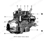
| Engine Photographs | 7-12 | Left and Right Engine Views, Component Identification, Engine Serial Number Location |
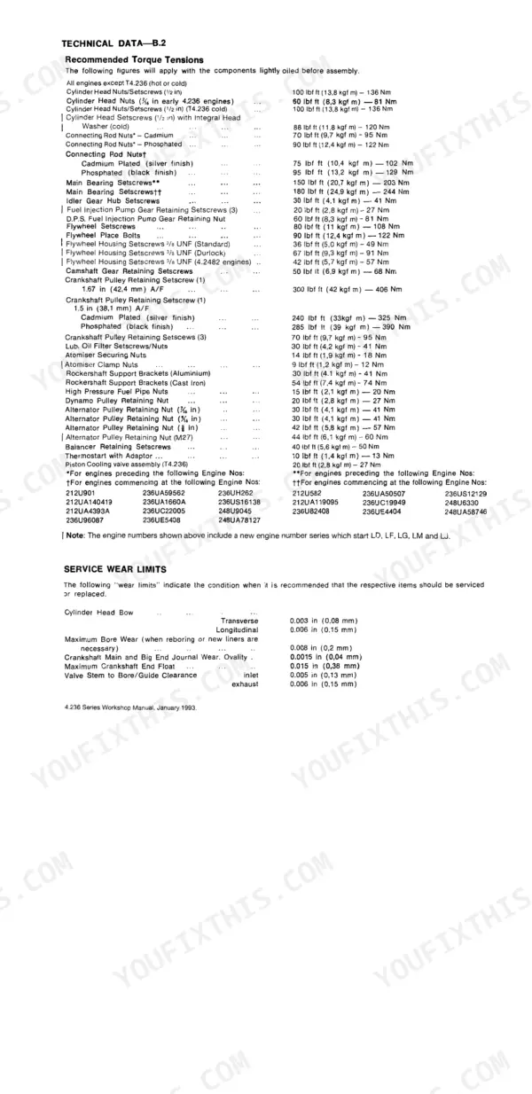
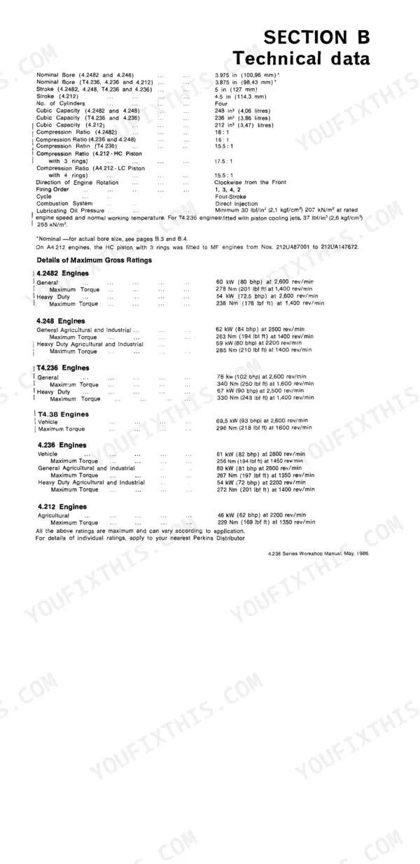
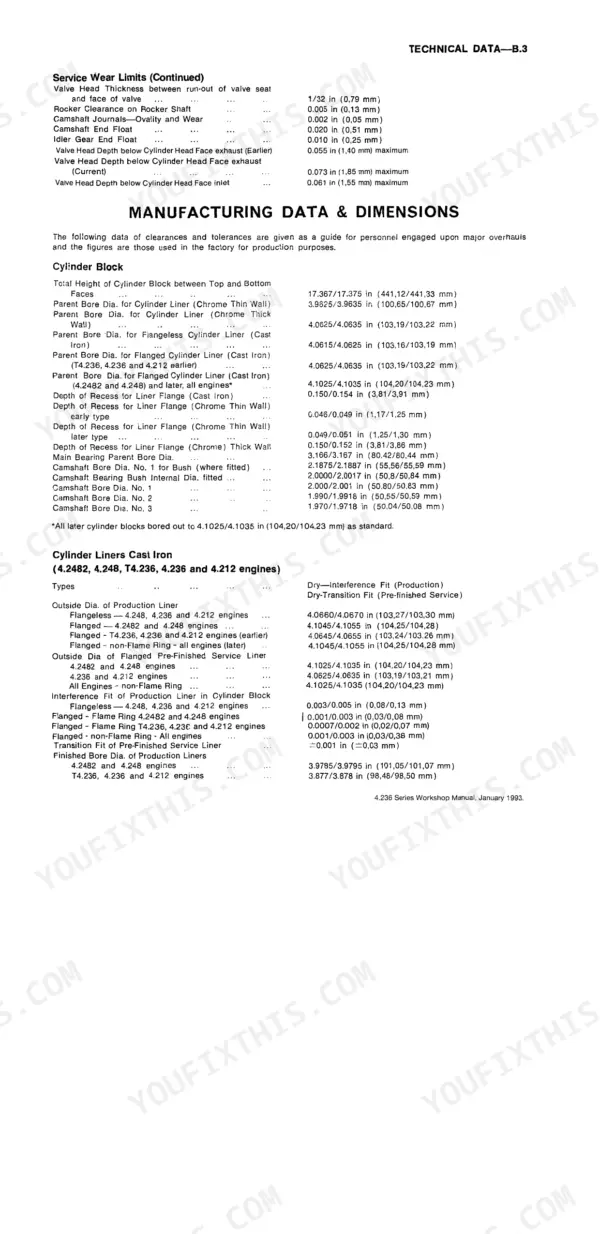
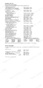
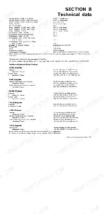
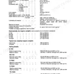
| Technical Data | 13-32 | Bore and Stroke, Compression Ratio, Valve Clearances, Piston and Ring Dimensions, Crankshaft and Bearing Clearances, Torque Values, Fuel Injection Data |
| Fault Diagnosis | 33-34 | Engine Will Not Start, Low Power, Misfiring, Excessive Oil Consumption, Black or Blue Exhaust Smoke, Low Oil Pressure, Overheating |
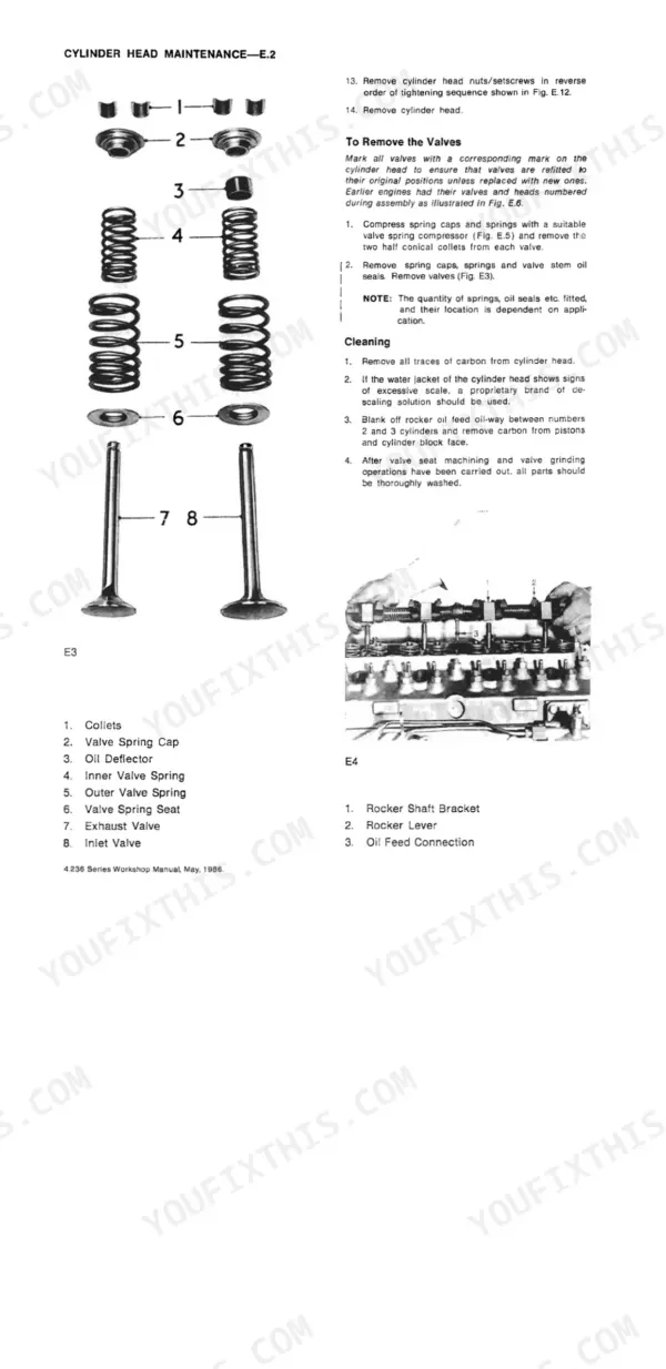
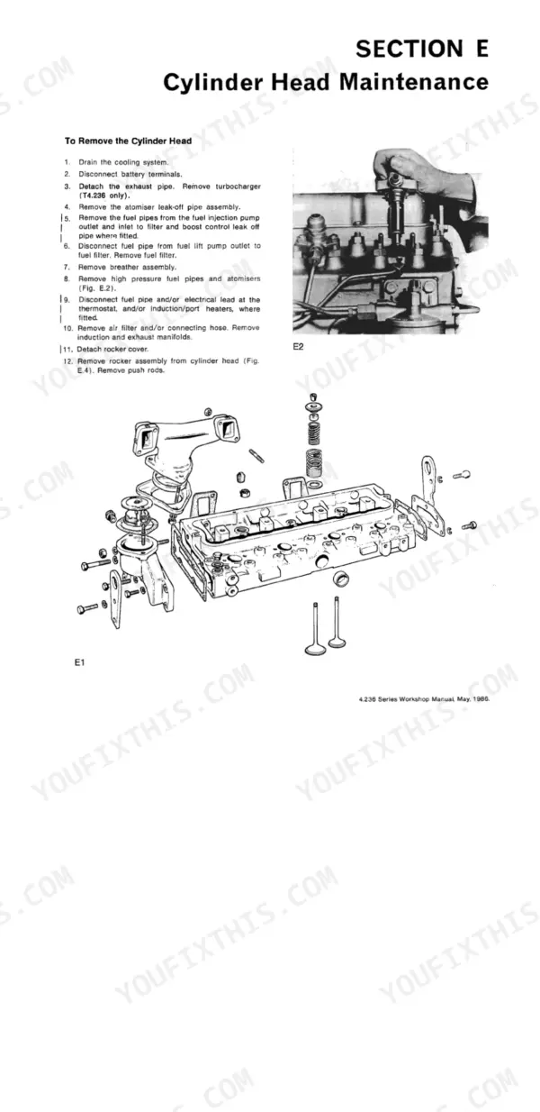
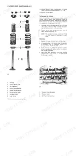
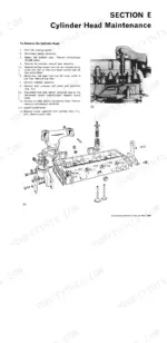
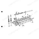
| Cylinder Head Maintenance | 35-42 | Cylinder Head Removal and Refitting, Valve and Valve Seat Servicing, Valve Guides, Valve Springs, Atomiser and High-Pressure Pipe Removal, Head Bolt Torque Sequence |
| Pistons and Connecting Rods | 43-48 | Piston Removal and Refitting, Piston Ring Gap and Groove Clearance, Connecting Rod Alignment, Small-End Bush Replacement, Big-End Bearing Clearance |
| Cylinder Block and Liners | 49-52 | Cylinder Liner Removal and Fitting, Liner Bore Wear Limits, Block Face Flatness, Core Plugs, Liner Protrusion Check |
| Crankshaft and Main Bearings | 53-58 | Crankshaft Removal, Main and Big-End Bearing Clearances, Thrust Washers and End-Float, Journal Regrinding Limits, Rear Oil Seal |
| Balancer Unit | 59-68 | Front-Mounted and Centre-Mounted Balancer Units, Removal and Refitting, Balancer Gear Backlash, Bearing Clearances, Timing Marks |
| Timing Case and Drive | 69-78 | Timing Case Removal, Idler Gear and Timing Gear Backlash, Fuel Pump Gear and Injection Pump Timing, Camshaft Gear, Front Oil Seal |
| Lubricating System | 79-86 | The Oil Pump, Lubricating Oil Filters |
| Cooling System | 87-92 | Water Pump Removal and Overhaul, Thermostat Testing, Radiator and Fan Belt Tension, Coolant Specification |
| Air Filters and Fuel System | 93-106 | Fuel Filters, Fuel Injection Pump, Fuel System Priming |
| Flywheel and Flywheel Housing | 107-108 | Flywheel Removal and Refitting, Ring Gear Replacement, Flywheel Housing Alignment, Torque Values |
| Exhauster | 109-112 | Description, Operation, Periodic Inspections and Preventive Maintenance, Removal, Dismantling, Re-Assembly |
| Compressor | 113-122 | S.C.6. Compressor, Wabco Compressor |
| Alternator, Dynamo and Starter Motor | 123-130 | Alternator, Starter Motor |
| Turbocharger | 131-134 | T4.236 Engines, Wastegate Turbocharger, To Remove Turbocharger, Airesearch T-31 Dismantling, Re-Assembly, To Fit Turbocharger |
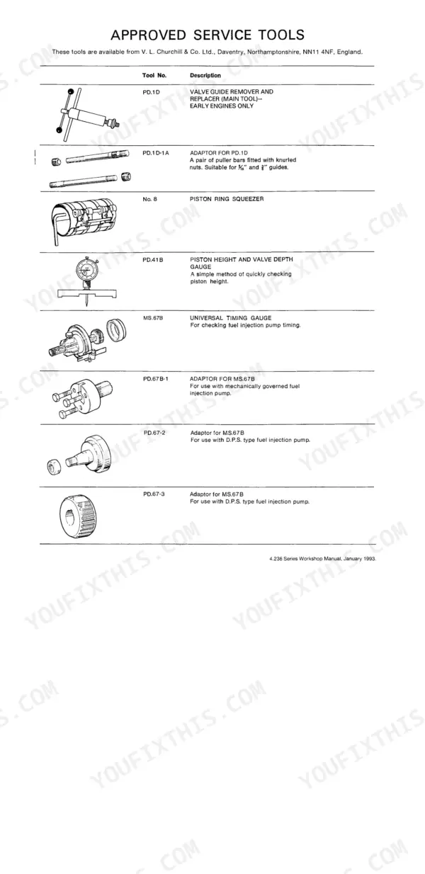
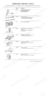
| Approved Service Tools | 135-138 | Valve Guide Remover and Replacer, Piston Ring Squeezer, Piston Height and Valve Depth Gauge, Universal Timing Gauge, Adjustable Valve Seat Cutters |
| Marine Supplement | 143-168 | Marine Engine Views, Cylinder Head, Heat Exchanger and Sea-Water Pump, Gearbox Adaptation, Marine Torque Values |
Quick Reference Specifications
| Specification | Value | Page |
|---|---|---|
| All Models | ||
| Cylinder head gasket | controlled swell type joints which are fitted dry | p. 5 |
| Fuel injection pump | high precision components | p. 5 |
| Cylinder head studs | in diameter | p. 4 |
| Plunger Dia. | 8,5 mm | p. 28 |
| Type of Filter | Full Flow | p. 26 |
| Torque Tension for Filter Bowl Retaining Screw (Element Type) | 15.0 lbf ft (2,07 kgf m) — 20 Nm | p. 26 |
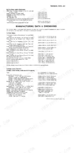
| Inside Dia.—Inlet and Exhaust | 0.375/0.376 in (9,53/9,55 mm) | p. 22 |
| Interference Fit of Guide in Cylinder Head Bore | 0.0002/0.0018 in (0,005/0,046 mm) | p. 22 |
| Type of Pump | Rotor Type | p. 24 |
| T4.38 engines | ||
| Maximum back pressure on fuel leak off from boost control capsule | 2 kPa | p. 28 |
| 4.2482 Engines | ||
| Top Compression Ring Width | 0.097/0.098 in (2,46/2,49 mm) | p. 17 |
| No. 1 Clearance in Groove | 0.0035/0.0054 in (0,09/0,14 mm) | p. 18 |
Perkins 4.212–4.248 Series Common Problems This Manual Covers
Perkins 4.236 head gasket leaking, coolant loss, white exhaust and lack of power under load
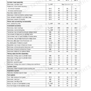
Remove the head and fit the new gasket dry; these are controlled swell joints and take no sealant (page 5). Torque the half inch head nuts and setscrews to 100 lbf ft (136 Nm) in sequence, then set valve clearances to 0.012 in (0.30 mm) cold per page 23 before running it up.
Manual Section: Cylinder Head Maintenance p. 35Engine cranks normally but won't start, or starts hard and misfires after filter change
Check for air in the fuel system before condemning the pump. Bleed at the filters and injection pump using the priming procedure on page 93. Renew both filter elements and torque the bowl retaining screw to 15 lbf ft (20 Nm). If it still won't fire, have the atomizers bench tested against the 30 atmospheres (440 lbf/in²) figure on page 100.
Manual Section: Air Filters and Fuel System p. 93Low oil pressure warning at idle when hot, gauge drops below normal at rated speed
Verify the reading with a known good gauge before tearing anything down. Check sump level and oil grade, then pull the relief valve covered on page 83; naturally aspirated engines set at 50/60 lbf/in² (345/414 kN/m²). If pressure stays low, measure oil pump gear clearance against page 82; it runs 0.003/0.007 in (0,08/0,18 mm).
Manual Section: Lubricating System p. 79Blue exhaust smoke and heavy oil consumption, needs topping up between service intervals
Measure valve guide bores first; inside diameter should read 0.375/0.376 in (9,53/9,55 mm), spec on page 22, and worn guides pass oil straight down the stems. If guides check out, pull the pistons per page 43 and compare ring gaps and groove clearances to the table for your specific variant. Renew rings and deglaze the bores.
Manual Section: Pistons and Connecting Rods p. 43Engine running hot, coolant boiling over after sustained load, temperature gauge climbing
Check coolant level cold; the engine holds 16.5 pints (9.36 litres) less radiator on industrial variants (page 26). Inspect fan belt tension and rod out the radiator. Test the thermostat in hot water; bellows types start opening at 170 to 180°F (77 to 83°C). Work through the overheating chart on page 33 before pulling the head.
Manual Section: Cooling System p. 87Frequently Asked Questions
What are the recommended service intervals for the engine components?
Service intervals vary by component. For the Exhauster, inspections are recommended every 5,000 miles (7,500 km) or 250 hours, with dismantling and inspection every 60,000 miles (90,000 km) or 2,500 hours. For the Compressor, visual checks are every 4 months or 5,000 miles (7,500 km), cleaning oil supply lines every 10,000 miles (15,000 km) or 500 hours, and dismantling every 60,000 miles (90,000 km) or 2,500 hours. p. 109
What are the fluid capacities for the engine and cooling system?
The engine's cubic capacity varies by model: 4.2482 and 4.248 engines have 248 in³ (4.06 litres), T4.236 and 4.236 engines have 236 in³ (3.86 litres), and 4.212 engines have 212 in³ (3.47 litres). The standard sump capacity is 14 pints (8 litres), and the engine water capacity (less radiator) is 16.5 pints (9.36 litres). p. 13
How do I troubleshoot an engine that won't start?
If the engine will not start, possible causes include low battery capacity, bad electrical connections, a faulty starter motor, or an empty fuel tank. Other issues could be a faulty stop control operation, blocked fuel feed pipe, faulty fuel lift pump, or a choked fuel filter. Refer to the Fault Finding Chart on page 33 for a comprehensive list of 33 potential causes. p. 33
What are the valve clearance specifications for the engine?
The valve clearance between the valve stem and rocker arm should be 0.012 in (0.30 mm) when the engine is cold. For earlier type camshafts (Part No. 31415291), the inlet valve clearance for timing is 0.034 in (0.86 mm), while later types (Part No. 31415292, 31415372 or 31415381) require 0.047 in (1.2 mm). p. 23
What are the torque specifications for cylinder head nuts/setscrews?
For most engines, cylinder head nuts/setscrews (1/2 in) should be tightened to 100 lbf ft (13.8 kgf m) - 136 Nm. For T4.236 engines, the setscrews should be tightened to 88 lbf ft (11.8 kgf m) 120 Nm (cold), followed by a full half turn. p. 14
What do I get after purchasing this Perkins 4.2482 & variants manual?
A 168-page Workshop Manual in searchable PDF format, available the moment you complete checkout. View on computer, tablet, or phone, with no shipping wait.
Is this Perkins 4.2482 & variants Workshop Manual printable?
Yes. Print a chapter or just the pages for the job at hand, for use in your own shop. Any home or office printer works.
Reviews
There are no reviews yet.