
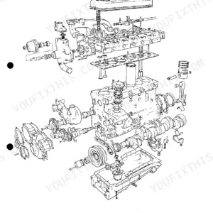
This 163-page Perkins 6.354 Workshop Manual (OEM #601SER03881O80) covers the full family: 6.354, T6.354, 6.3542, and 6.372 diesel engines, right down to the auxiliary drive housing where you'll find the engine number. Inside you get complete teardown and rebuild procedures for the cylinder head, crankshaft, timing case, and turbocharger, plus a full fault diagnosis section for low cranking speed, misfiring, and overheating complaints. You also get wiring diagrams for the alternator, dynamo, and starter motor circuits, so you're not tracing grounds with a test light and a guess. Set fuel injector opening pressure to 175 atm (181 kgf/cm²) and check pulley shaft diameter at 0.7492-0.7497 in (19.03-19.04 mm) before you button up the front end. No more flipping through three different reprints hoping the torque spec matches your block. Bookmarked by section, this PDF opens on your phone or tablet right at the bench, ready when you are.
What's Inside This Perkins 6.354, T6.354, 6.3542, 6.372 Manual
| System | Pages | Key Topics |
|---|---|---|
| Engine Photographs | 7-12 | Alternator Pulley, Water Pump Outlet, Lubricating Oil Filler, Fuel Oil Filter, Cylinder Head Cover, Atomiser |
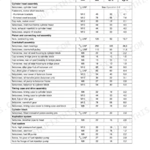
| Technical Data | 13-30 | Manufacturing Data and Dimensions, Fits and Tolerances, Torque Values, Engine Capacity and Bore/Stroke, Compression Ratio, Wear Limits |
| Operating and Maintenance | 31-34 | Starting the Engine, To Stop the Engine, Preventive Maintenance, Every 5, 000 Miles, Every 10, Engine Coolant |
| Fault Diagnosis | 35 | Low Cranking Speed, Will Not Start, Lack of Power, Misfiring, Low Oil Pressure, Overheating |
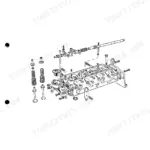
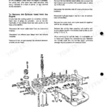
| Cylinder Head | 36-44 | To Remove the Cylinder Head, Valve Guides, Valves and Valve Seats, Valve Seat Inserts, Skimming of Cylinder Head, Rocker Shaft Assembly |
| Pistons and Connecting Rods | 45-49 | To Remove Piston and Connecting Rod Assemblies, To Remove Pistons From the Connecting Rods, Inspection, To Assemble the Pistons to the Connecting Rods, Fitting New Pistons |
| Cylinder Block and Liners | 50-52 | To Renew Cylinder Liners (Cast Iron Flangeless), To Renew Cylinder Liners (Chrome Plated), To Renew Cylinder Liners (Cast Iron Flanged) |
| Crankshaft and Main Bearings | 53-60 | Crankshaft Removal and Refitting, Main Bearings and Journals, End Float Check, Rope Type Rear End Oil Seal, Thrust Washers, Regrinding Limits |
| Timing Case and Drive | 61-71 | Timing Case Cover Removal, Idler Gear and Bushes, Auxiliary Drive Shaft, Fuel Pump Drive Shaft, Timing Gear Backlash, Front Oil Seal |
| Lubricating System | 72-80 | Oil Pump, Oil Pressure Relief Valve, Oil Filter and Cooler, Sump and Strainer, Oil Pressure Testing, Lubricating Oil Grades |
| Cooling System | 81-86 | Water Pump Overhaul, Thermostat (Opens 77-83 °C), Radiator and Header Tank, Fan and Belt Adjustment, Coolant Capacity, Pressure Cap |
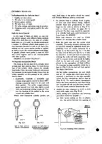
| Air Cleaners and Fuel System | 87-98 | Air Cleaners (Oil Bath and Dry), Fuel Injection Pump, Injectors and Setting Pressure, Fuel Filter and Lift Pump, Bleeding the Fuel System, Pump Timing |
| Flywheel and Housing | 99-101 | To Remove the Flywheel, To Renew the Flywheel Ring Gear, To Refit the Flywheel, To Remove the Flywheel Housing, To Refit the Flywheel Housing, Alignment Limits |
| Turbocharger | 102-124 | Turbocharger Installation, Reconditioning Instructions, Bearings and Shaft Clearances, Boost Pressure, Oil Feed and Drain, Fault Diagnosis |
| Alternator, Dynamo and Starter Motor | 125-134 | Alternator Output and Overhaul, Dynamo, Starter Motor Removal and Brush Replacement, Drive Pinion, Charging Circuit Tests |
| Compressor | 135-151 | S.C.6. Compressor, Bendix Westinghouse Twin 9 Compressor, Removal and Installation, Overhaul, Unloader Valve, Drive |
| Exhauster | 152-154 | Description, Operation, Servicing Exhauster, To Remove the Exhauster, Dismantling, Re-Assembly |
| Fuel and Lubricating Oil Specifications | 155 | Fuel Specification, Lubricating Oil Specification, Cetane Number, Viscosity, Density, Recommended Sae Viscosity Grades |
| Approved Service Tools | 156-159 | Valve Guide Remover and Replacer, Timing Tool with Adaptor, Piston Ring Squeezer, Piston Height and Valve Depth Gauge, Camshaft Bush remover/replacer |
| Service Facilities | 163 | Workshop Manuals, Operators Handbooks, Crankshaft Regrinding, Fault Finding Guide, Engine Brake Testing Data, Installation and Maintenance Guide for Static Standby Engines |
Quick Reference Specifications
| Specification | Value | Page |
|---|---|---|
| 6.354, T6.354, 6.3542, 6.372 | ||
| Fuel Injector Setting Pressure | 175 atm (181 kgf/cm²) | p. 26 |
| All Models | ||
| Water Pump Shaft Outside Diameter | 0.7492/0.7497 in (19,03/19,04 mm) | p. 25 |
| Water Pump Pulley Inside Diameter | 0.7500/0.7508 in (19,05/19,07 mm) | p. 25 |
| Valve Guide Internal Diameter | 0.3743/0.3764 in (9,51/9,56 mm) | p. 20 |
| Valve Stem Outside Diameter | 0.6260/0.6264 in (15,90/15,91-mm) | p. 20 |
| Thermostat Opening Temperature | 170/182°F (77/83°C) | p. 25 |
| Thermostat Fully Open Temperature | 202°F (94°C) | p. 25 |
| Turbocharged Engines | ||
| Compression Ring Width-Top Ring | 0.124/0.125 in (3,15/3,175 mm) | p. 17 |
| Compression Ring Width-2nd and 3rd Rings | 0.0928/0.0938 in (2,36/2,38 mm) | p. 17 |
| 6.3542, T6.354 and 6.354 Engines (Cast Iron - Flangeless) | ||
| Interference Fit of Liner | Dry-Interference Fit | p. 15 |
| Inside Diameter of Liner after Finish Honing | 0.003/0.005 in (0,076/0,127 mm) | p. 15 |
Perkins 6.354, T6.354, 6.3542, 6.372 Common Problems This Manual Covers
Perkins 6.354 series excessive oil consumption and rapid oil level drop during normal operation
Inspect the cylinder liners for wear exceeding the maximum bore wear of 0.008 in (0.2 mm) as noted on page 30. Check the oil drain pipe every 20,000 miles (30,000 km) or 1,000 hours as specified on page 113. Replace worn piston rings if clearance exceeds limits.
Manual Section: Fault Diagnosis p. 35Severe overheating at heavy loads with coolant boiling over and temperature gauge spiking
Test the thermostat opening temperature against the value stamped on the top face adjacent to the valve seat, per page 85. Inspect the water pump impeller to body clearance and verify it measures 0.012/0.035 in (0,30/0,89 mm) as shown on page 83. Replace components if out of specification.
Manual Section: Cooling System p. 81Engine cranks but won't start or experiences hard starting despite having fresh fuel and good batteries
Verify the fuel injection pump timing. Check page 94 to ensure the scribed line on the rotor marked H aligns with the timing circlip for hydraulically governed engines. Torque the atomiser securing nuts to 16 Nm as directed on page 76 to prevent compression leaks.
Manual Section: Air Cleaners and Fuel System p. 87Low oil pressure at operating temperature accompanied by loud knocking or rattling from lower engine
Measure the oil pressure at maximum running speed. Verify it reaches a minimum of 30 lbf/in² (2,1 kgf cm²) 207 kN/m² as specified on page 77. Remove the sump and torque the sump screws to 12/14 Nm according to page 74. Inspect main bearings for wear.
Manual Section: Lubricating System p. 72Frequently Asked Questions
What are the torque specifications for Perkins 6.354 cylinder head bolts?
The torque specification for cylinder head nuts (and/or setscrews) is 100 lbf ft (13.8 kgf m) or 136 Nm. For 5/8 inch cylinder head nuts, the torque is 60 lbf ft (8.3 kgf m) or 81 Nm. Note that 1/2 inch cylinder head nuts were fitted from Engine No. 8060000 onwards. p. 14
How do you set the fuel injection timing for Perkins 6.3542 engines?
To set the fuel injection timing, position No. 1 piston at T.D.C. on its compression stroke. Then, use timing tool MS67B to position the crankshaft so that the piston is 0.372 in (9,45 mm) B.T.D.C., which is equivalent to 28° B.T.D.C. on the flywheel. p. 94
What is the flywheel torque specification for Perkins 6.372 engines?
The flywheel setscrews should be tightened to a torque of 80 lbf ft (11.1 kgf m) or 108 Nm. This specification applies generally to the engine types covered in the manual. p. 14
How do you reset the Perkins 6.3542 fuel system?
To reset the fuel system, you need to prime it by venting air. Slacken the air vent valve on the control gear housing and the vent valve on the hydraulic head locking screw. Operate the priming lever on the fuel feed pump until fuel, free from air bubbles, issues from each venting point, then tighten the screws. p. 98
What are the replacement specifications for Fuel injectors?
When replacing atomisers, ensure a new, correct type copper washer is fitted between the nozzle cap and the cylinder head. The atomiser securing nuts should be tightened evenly to 12 lbf ft (1.7 kgf m) or 16 Nm. Specific atomiser types, like BKBL67S5100 with nozzle BDLL150S6225, have a setting pressure of 175 atm (2570 lbf/in²). p. 96
Do I get instant access to this Perkins 6.354 Workshop Manual?
You get a 163-page searchable PDF that downloads instantly after checkout. Open it on your laptop, tablet, or phone, and bring it right to the shop floor.
Am I free to print this Perkins 6.354 Workshop Manual?
Yes. Many mechanics print the section they need for their own shop and bring it to the bench.
Reviews
There are no reviews yet.