


Part of the Yanmar Repair Manuals.
All 463 pages of this Yanmar Marine Diesel Engine Service Manual (OEM #0000A0A1361) cover the 1985 GM and HM family: 1GM10(C), 2GM20(F)(C), 3GM30(F)(C), and 3HM35(F)(C). Inside you get full wiring diagrams for the 12V electrical system, exploded-view drawings across every major assembly, system diagrams for both direct sea-water and fresh water cooling circuits, a complete troubleshooting section, and step-by-step disassembly and reassembly procedures for each variant. The fuel system chapter walks you through injection pump, nozzle, and filter service: clean the filter at 50 hours, swap the element every 250. Set injection nozzle opening pressure to 170 ±5 kgf/cm² and watch your direct sea-water thermostat, opening at 42 ±2°C and goes fully open at 52 ±2°C. Your engine is sitting dead in the slip. Bookmarked and keyword-searchable, this PDF puts the factory answer on your tablet before you touch a wrench.
What's Inside This Yanmar 1GM10, 2GM20, 3GM30, 3HM35 Manual
| System | Pages | Key Topics |
|---|---|---|
| A. Engine Model Name | 4 | - |
| B. Engine Model Name Plate and Clutch Model Name Plate | 5-6 | - |
| Cylinder Number | 7 | - |
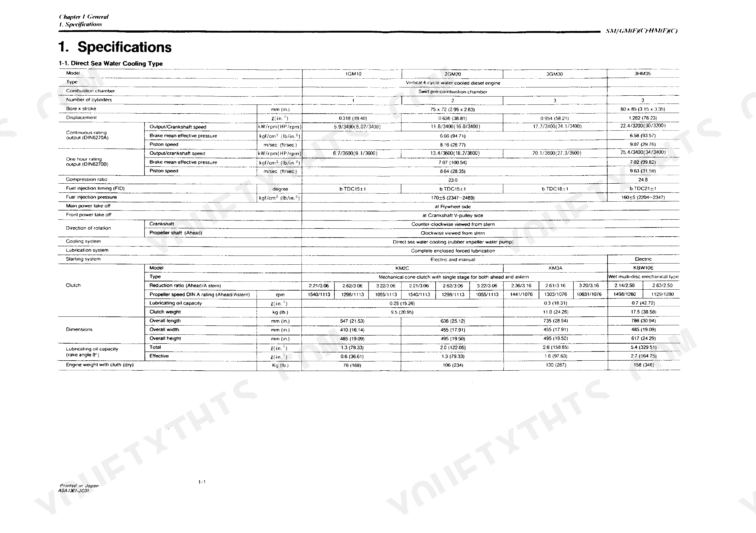
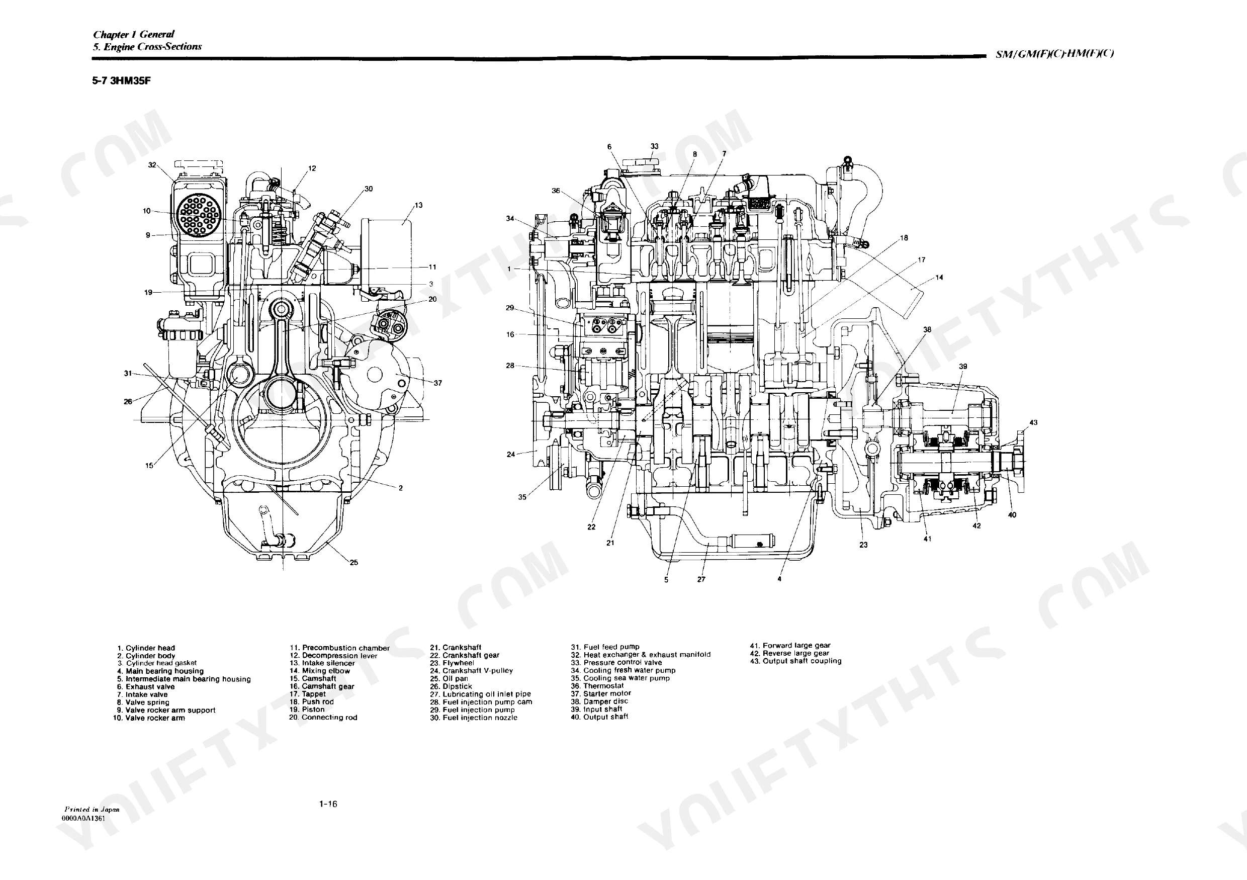
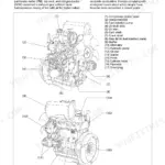
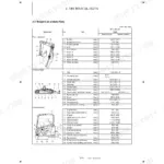
| General | 8-36 | Specifications, Principal Construction, Performance Curves, Features |
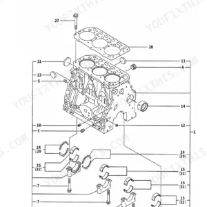
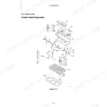
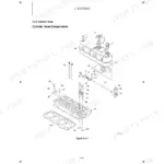
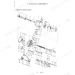
| Basic Engine | 37-100 | Cylinder Block, Cylinder Head, Piston, Connecting Rod, Crankshaft, Flywheel and Housing |
| Fuel System | 101-135 | Fuel Injection System, Injection Pump, Injection Nozzle, Fuel Filter, Fuel Feed Pump, Fuel Tank |
| Governor | 136-149 | Injection Limiter, No-Load Maximum Speed Limiter, Idling Adjuster, Engine Stop Lever |
| Intake and Exhaust System | 150-157 | Intake Silencer, Exhaust System, Breather |
| Lubrication System | 158-172 | Oil Pump, Oil Filter, Oil Pressure Regulator Valve, Oil Pressure Measurement |
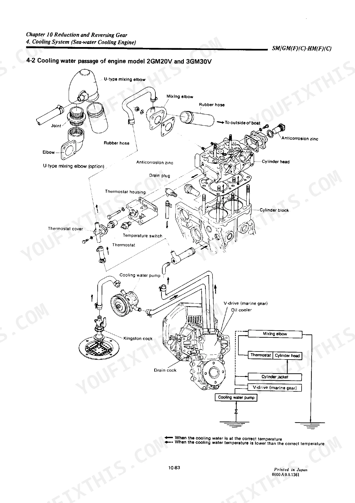
| Direct Sea-Water Cooling System | 173-190 | Cooling System, Water Pump, Thermostat, Anticorrosion Zinc, Kingston Cock, Bilge Pump and Bilge Strainer |
| Fresh Water Cooling System | 191-209 | Cooling System, Sea Water Pump, Fresh Water Pump, Heat Exchanger, Filler Cap and Subtank, Thermostat |
| Modifying the Cooling System | 210-222 | General, Disassembly of Sea Water-Cooled Engine, Assembling Modified Parts to the Fresh Water-Cooled Engine, Cautions When the Engine Is Installed Inboard |
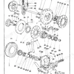
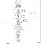
| Reduction and Reversing Gear | 223 | Construction, Shifting Device, Inspection and Servicing, Disassembly, Reassembly |
| [A] for Engine Models 1GM10.2GM20(F) and 3GM30(F) | 224-251 | Construction, Shifting Device, Inspection and Servicing, Disassembly, Reassembly |
| [B] for Model 3GM35(F) | 252-272 | Construction, Installation, Operation and Maintenance, Inspection and Servicing, Disassembly, Reassembly |
| [C] Marine Gear Models KM2P,KM3P, and KM3V for Engine Models 1GM10, 2GM20(F) and | 273-299 | Construction, Shifting Device, Inspection and Servicing, Disassembly, Reassembly |
| [D] V-Drive Gear, Model KM3V | 300-322 | Construction, Specifications, Power Transmission System, Cooling System, Piping Diagrams, Inspection and Servicing |
| Remote Control System | 323-330 | Construction, Clutch and Speed Regulator Remote Control, Engine Stop Remote Control |
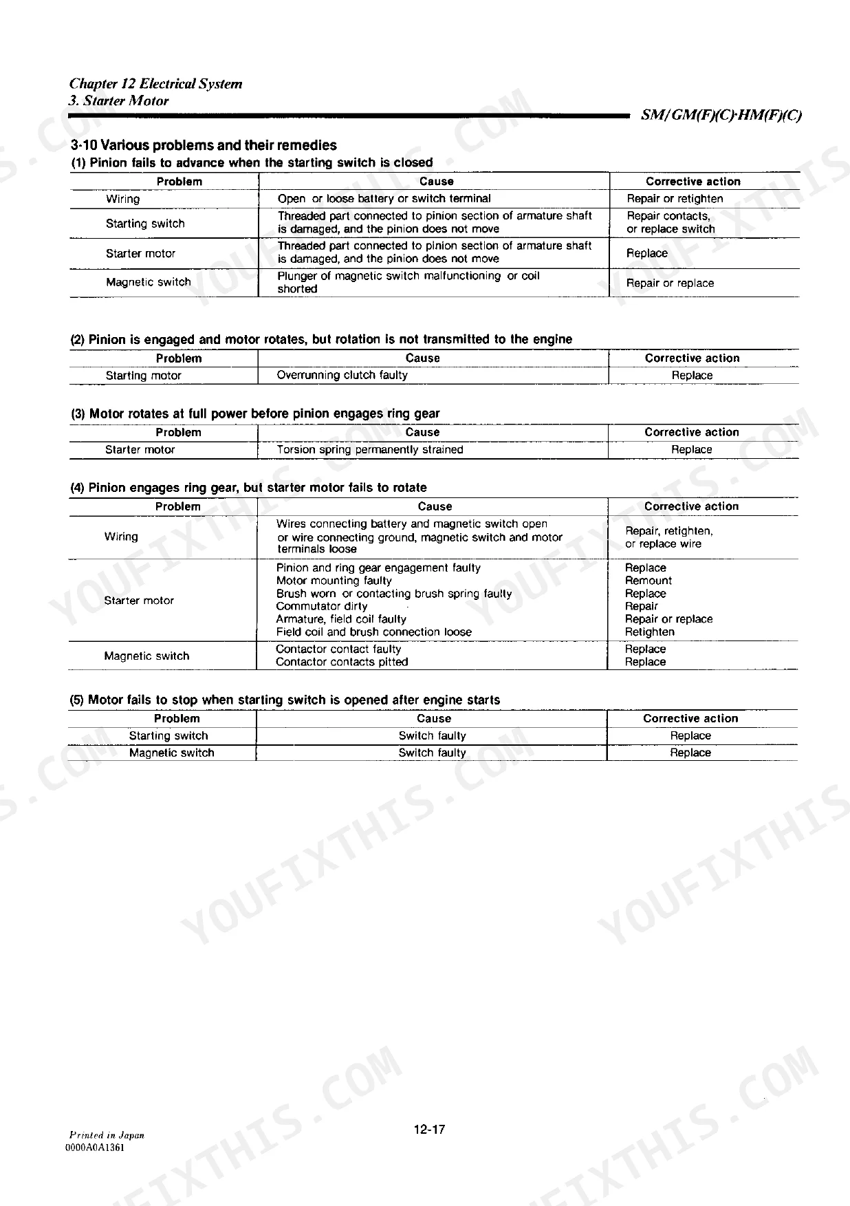
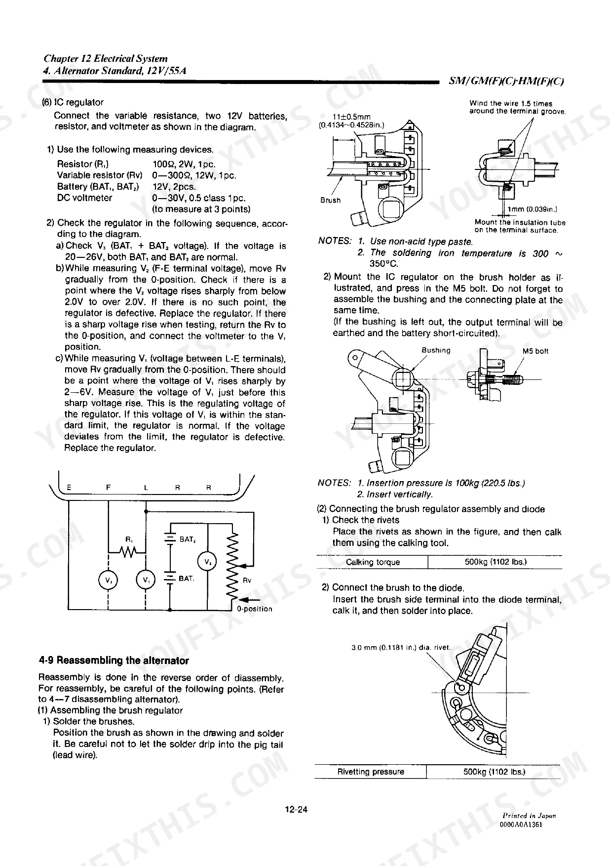
| Electrical System | 331-376 | Battery, Starter Motor, Alternator Standard, 12V/55A, Alternator Option, 12V/35A, Instrument Panel |
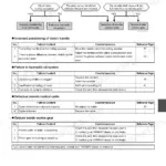
| Operating Instructions | 377-392 | Fuel Oil and Lubricating Oil, Engine Operating Instructions, Troubleshooting and Repair |
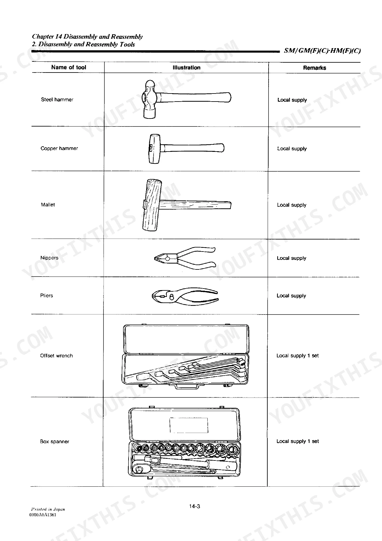
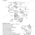
| Disassembly and Reassembly (Direct Sea-Water Cooling Engine) | 393-436 | Disassembly and Reassembly Precautions, Disassembly and Reassembly Tools, Others, Disassembly, Reassembly |
| Disassembly and Reassembly (Fsesh Water Cooling Engine) | 437-463 | Disassembly of Fresh Water-Cooled Engine, Reassembly of Fresh Water-Cooled Engine, Tightening Torque, Packing Supplement and Adhesive Application Point |
Quick Reference Specifications
| Specification | Value | Page |
|---|---|---|
| All Models | ||
| Fuel filter cleaning interval | First time 50 hours | p. 133 |
| Fuel filter element replacement interval | Every 250 hours | p. 133 |
| Thermostat opening temperature (Direct Sea-Water Cooling System) | 42 ±2°C | p. 181 |
| Thermostat full open temperature (Direct Sea-Water Cooling System) | 52 ±2°C | p. 181 |
| Anticorrosion zinc tightening torque | 5~6 kgf·m (36.165~43.398 ft·lb) | p. 460 |
| Oil pan packing agent (timing gear) | Three Bond 388-005 | p. 461 |
| Heat exchanger leakage test air pressure | 0.5~2.0 kgf/cm² (7.11~28.45 lb/in.²) | p. 200 |
| Oil Pump Discharge Pressure (Maintenance Standard) | 3.5 ± 0.5 kgf/cm² (42.67 ~ 56.89 lb/in.²) | p. 165 |
| 1GM10(C), 2GM20(F)(C), 3GM30(F)(C) | ||
| Injection nozzle valve opening pressure | 170±5 kgf/cm² (2347~2489 lb/in.²) | p. 130 |
| 3HM35(F)(C) | ||
| Injection nozzle valve opening pressure | 160±5 kgf/cm² (2205~2347 lb/in.²) | p. 130 |
| 2GM20(C), 3GM30(C), 3HM35(C) (Direct Sea-Water Cooling System) | ||
| Water pump V-belt tension (deflection at 10kg force) | 5~7 mm (0.1969~0.2756 in.) | p. 180 |
Yanmar 1GM10, 2GM20, 3GM30, 3HM35 Common Problems This Manual Covers
Yanmar 1GM10/2GM20/3GM30/3HM35 fuel system draws air after filter changes, engine cranks but won't start
Check the bleeding procedure on page 101. Open the bleed screw on the fuel filter housing and crank the lift pump manually until fuel flows bubble-free. Replace the filter element every 250 hours; first cleaning is due at 50 hours (page 133). A partially clogged element is the leading cause of air ingestion after filter service on these engines.
Manual Section: Fuel System p. 101Engine overheats under load, raw-water stream slows or stops and alarm triggers at the helm
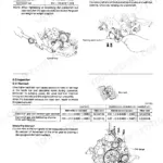
Inspect the raw-water impeller first; a failed impeller kills flow instantly. Then check the thermostat: it should begin opening at 42 ±2°C and reach full open at 52 ±2°C (page 181). On fresh-water-cooled models, pressure-test the heat exchanger at 0.5~2.0 kgf/cm² (7.11~28.45 lb/in.²) per page 200 to find internal leaks before pulling the exchanger.
Manual Section: Direct Sea-Water Cooling System p. 173Engine cranks but won't fire, or fires with white smoke and rough idle after warmup
Check valve clearances and compression before condemning injectors; low compression mimics nozzle failure. If compression is within spec, test the nozzle on a pop tester: opening pressure should be 170 ±5 kgf/cm² (2347~2489 lb/in.²) for 1GM10(C)/2GM20(F)(C)/3GM30(F)(C), or 160 ±5 kgf/cm² for the 3HM35(F)(C) (page 130). A weak or ragged spray means the nozzle needs service.
Manual Section: Fuel System p. 130Oil pressure warning lamp illuminates at idle or oil pressure drops after extended running
Measure oil pressure at the gallery before dismantling; maintenance standard is 3.5 ±0.5 kgf/cm² (42.67~56.89 lb/in.²) at operating temperature (page 165). Verify oil level and viscosity first. A confirmed low reading with correct oil level points to pump wear or a clogged pickup screen. Inspect the oil pump and regulator valve per page 165, not just replacing the pressure sender.
Manual Section: Lubrication System p. 165Raw-water flow drops and belt squeals on direct-cooled models, impeller checks out clean
Inspect the V-belt tension on 2GM20(C), 3GM30(C), and 3HM35(C): deflection under a 10 kg load should be 5~7 mm (0.1969~0.2756 in.) at mid-span (page 180). A loose belt slips at speed and starves the pump without audible cavitation. Replace the belt if it shows glazing or cracking; check pulley alignment before fitting the new one.
Manual Section: Direct Sea-Water Cooling System p. 180Frequently Asked Questions
How to bleed the fuel system thoroughly including the high-pressure side to the injector?
To bleed the fuel system, first open the fuel tank cock. Then, bleed the air from the fuel filter and the fuel injection pipe. This involves loosening the air bleeding plug at the top of the fuel filter body and operating the manual handle of the fuel pump until no more bubbles appear, then tightening the plug. p. 385
How will I receive this Yanmar 1GM10(C), 2GM20(F)(C), 3GM30(F)(C), 3HM35(F)(C)?
A 463-page Service Manual in searchable PDF format (13 MB), available the moment you complete checkout. View on computer, tablet, or phone, with no shipping wait.
Can I print this Yanmar 1GM10(C), 2GM20(F)(C), 3GM30(F)(C), 3HM35(F)(C) manual?
Absolutely. No DRM or copy protection. Print the whole manual or just the pages you need. Any home or office printer works.
Does this Yanmar 1GM10(C), 2GM20(F)(C), 3GM30(F)(C), 3HM35(F)(C) manual?
Included. The Yanmar 1GM10(C), 2GM20(F)(C), 3GM30(F)(C), 3HM35(F)(C) Service Manual covers complete wiring harness diagrams, electrical circuits, and connector pinouts.

Reviews
There are no reviews yet.