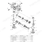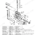

Part of the Yanmar Repair Manuals.
Guess at a torque on a travel motor and a fifteen minute job can end with a machine on blocks and a crew standing around it, which is exactly what the 328 pages of this Yanmar SV20 service manual are there to prevent. It covers the SV20 mini excavator and its 3TNV76-PBVA diesel, from compression measurement and valve clearance through the hydraulic pump, control valve, pilot valve, swing motor and travel motor.
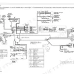
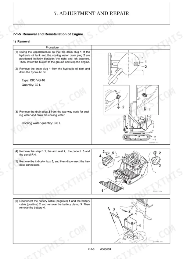
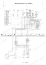
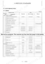
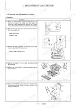
The Service Standards section lists wear limits for the undercarriage, rubber crawlers, idlers and hydraulic cylinders, plus tightening torque tables for machine and engine. Adjustment and Repair walks through removal and reinstallation of the engine, starter motor, fuel injection pump and radiator, with wiring diagrams and the monitor and alarm circuits.
It is a bookmarked PDF, so it lives on a phone or laptop and rides in the cab, on hand wherever the machine quits.
What's Inside This Manual
| System | Pages | Key Topics |
|---|---|---|
| General Cautions for Maintenance Work | 11-24 | Correct Work, Safety Precautions, Preparations, Cautions for Disassembly and Reassembly, Cautions for Removal and Installation of Hydraulic Equipment |
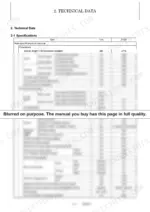
| Technical Data | 25-36 | 2-1 Specifications, 2-2 Outline Drawing and Working Area, 2-3 Weight List of Main Parts, 2-4 Lifting Capacity List |
| Service Standards | 37-56 | Machine Performance, Engine, Undercarriage (Rubber Crawler Specifications, Common Specifications of Steel & Rubber Crawlers), Controls, Hydraulic Equipment (Hydraulic Cylinders) |
| Engine | 57-100 | General (Engine External Views), Measurement |
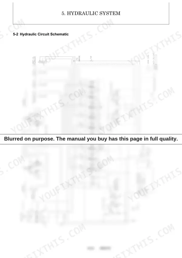
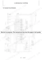
| Hydraulic System | 101-104 | 5-1 Outline, 5-2 Hydraulic Circuit Schematic |
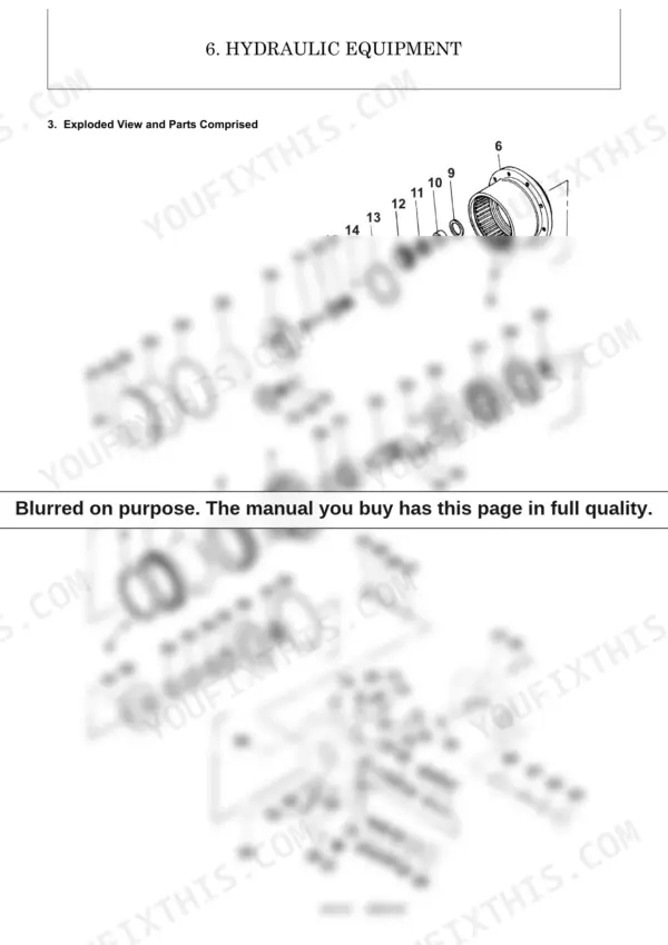
| Hydraulic Equipment | 105-198 | 6-1 Hydraulic Pump, 6-2 Control Valve, 6-3 Pilot Valve, 6-4 Swing Motor, 6-5 Travel Motor |
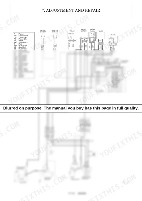
| Adjustment and Repair | 199-276 | Electric Equipment of Machine (Parts Layout of Electrical Equipment, Monitor and Alarm Systems, Wiring Diagram, Circuit Description of Engine Start and Stop, And Battery Charging, Removal and Reinstallation of Engine, Removal and Reinstallation of Starter Motor, Removal and Reinstallation of Fuel Injection Pump, Removal and Reinstallation of Fuel Tank, Removal and Reinstallation of Radiator) |
| Periodic Inspection and Servicing | 277-280 | 8-1 List of Periodic Inspection and Servicing |
| Fuel, Lube Oil and Grease Recommended | 281-284 | Engine Oil, Travel Reduction Gear, Hydraulic Oil, Fuel, Engine Cooling Water, Grease |
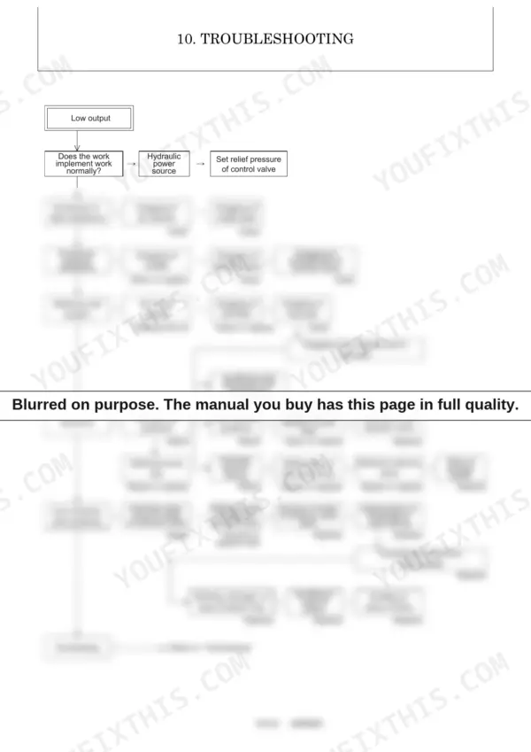
| Troubleshooting | 285-324 | 10-1 Non-Breakdowns, 10-2 Troubleshooting |
| Reference Data | 325-328 | 11-1 Specifications for Attachment |
Quick Reference Specifications
| Specification | Value | Page |
|---|---|---|
| LS pressure relief valve adjustment torque | 20 ± 10% N.m | p. 123 |
| Travel motor valve body assembly to base plate bolts (Hexagon socket head bolt 79) | 14.4 to 15.9 N·m | p. 189 |
| Hydraulic pump cover bolts (Screw Tcei M 10X50 UNI 5931-12.9) | 70 Nm | p. 113 |
| Rubber crawler wear limit (A) | 10 mm | p. 47 |
| Idler & shaft D (diameter) wear limit | Ø279 | p. 45 |
| Hose type (SAE J517, 100R1) 02 working pressure | 17.2 MPa | p. 17 |
| Hose clip 13 tightening torque | 2.5 to 3.4 N·m | p. 52 |
| Floating seal 2 replacement condition | No excessive flaws, wear or seizure | p. 192 |
| Oil seal 30 replacement condition | No flaws, distortion or excessive wear. Not hardened | p. 191 |
| Fuel filter element replacement interval | Every 200 hrs | p. 278 |
| Engine oil filter element replacement interval | Every 250 hrs | p. 277 |
| Air cleaner element replacement interval | Every 250 hrs | p. 277 |