


Part of the Yanmar Repair Manuals.
All 530 pages of this Yanmar B7-3(US) Service Manual (OEM #4630010) zero in on one machine: your compact excavator, from crawler undercarriage to hydraulic pump and everything between. You get a full hydraulic circuit schematic with circuit-by-circuit operation for boom, arm, bucket, swing, blade, and travel; wiring diagrams covering the complete electrical system with monitor and alarm layouts; plus a torque reference table specifying M8 pipe joint bolts at 9.40–12.32 ft·lbf and M12 at 18.07–25.30 ft·lbf. Torque the bleeder valve fitting to 3.61–5.06 ft·lbf, keep the hose inside diameter at 0.20 in., and bleed air from the hydraulic circuit before startup. Your Yanmar b7-3(us) service manual pdf search is over. Every hour the machine sits idle costs money. Bookmarked and keyword-searchable, so you jump straight to the right procedure, pull up the spec, and get the excavator back in the ground.
What's Inside This Yanmar B7-3(US) Manual
| System | Pages | Key Topics |
|---|---|---|
| General Cautions for Maintenance Work | 7-18 | Correct Work, Safety Precautions, Preparations, Cautions for Disassembly and Reassembly, Cautions for Removal and Installation of Hydraulic Equipment |
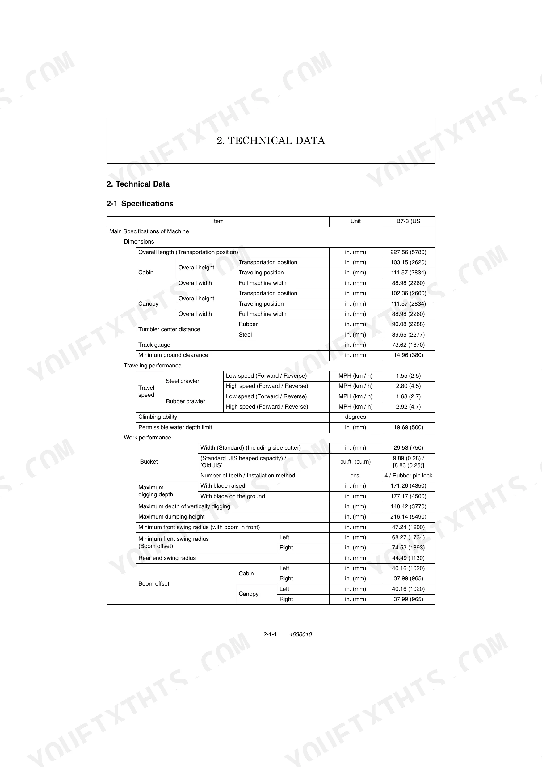
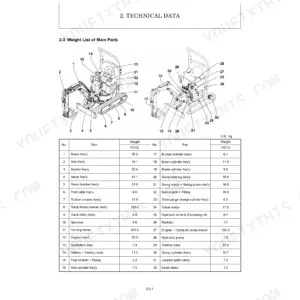
| Technical Data | 19-32 | Specifications, Outline Drawing and Working Area (Canopy Type, Cabin Type), Weight List of Main Parts, Lifting Capacity List |
| Service Standards | 33-52 | Machine Performance, Engine, Undercarriage (Rubber Crawler Specifications, Steel Crawler Specifications, Common Specifications of Steel & Rubber Crawlers), Controls |
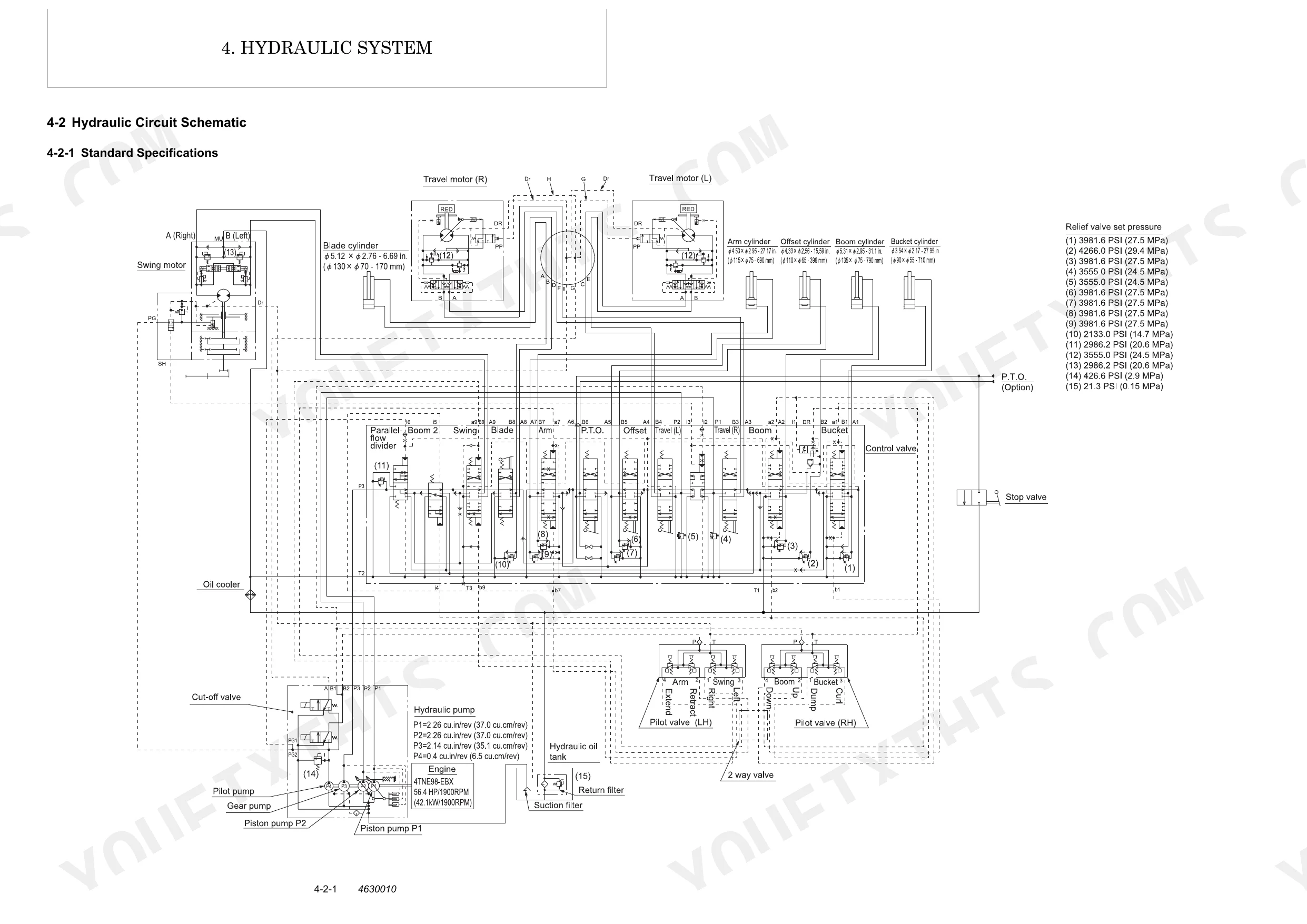
| Hydraulic System | 53-90 | Outline (Control Valve Operation, Additional Operation of Control Valve), Hydraulic Circuit Schematic (Standard Specifications) |
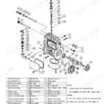
| Hydraulic Equipment | 91-264 | Removal and Reinstallation of Hydraulic Pump, Removal and Reinstallation of Control Valve, Removal and Reinstallation of Swing Motor, Removal and Reinstallation of Swivel Joint |
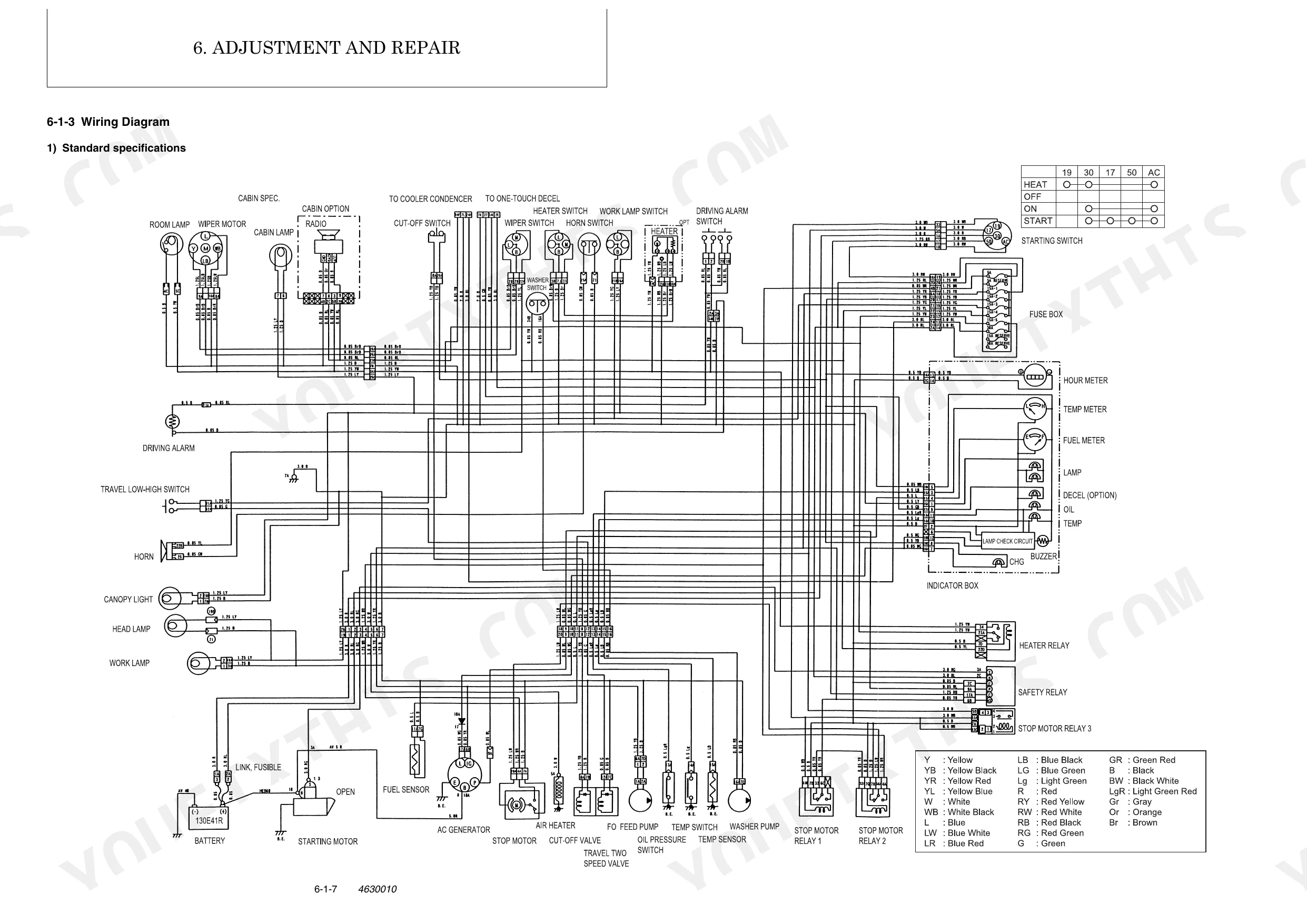
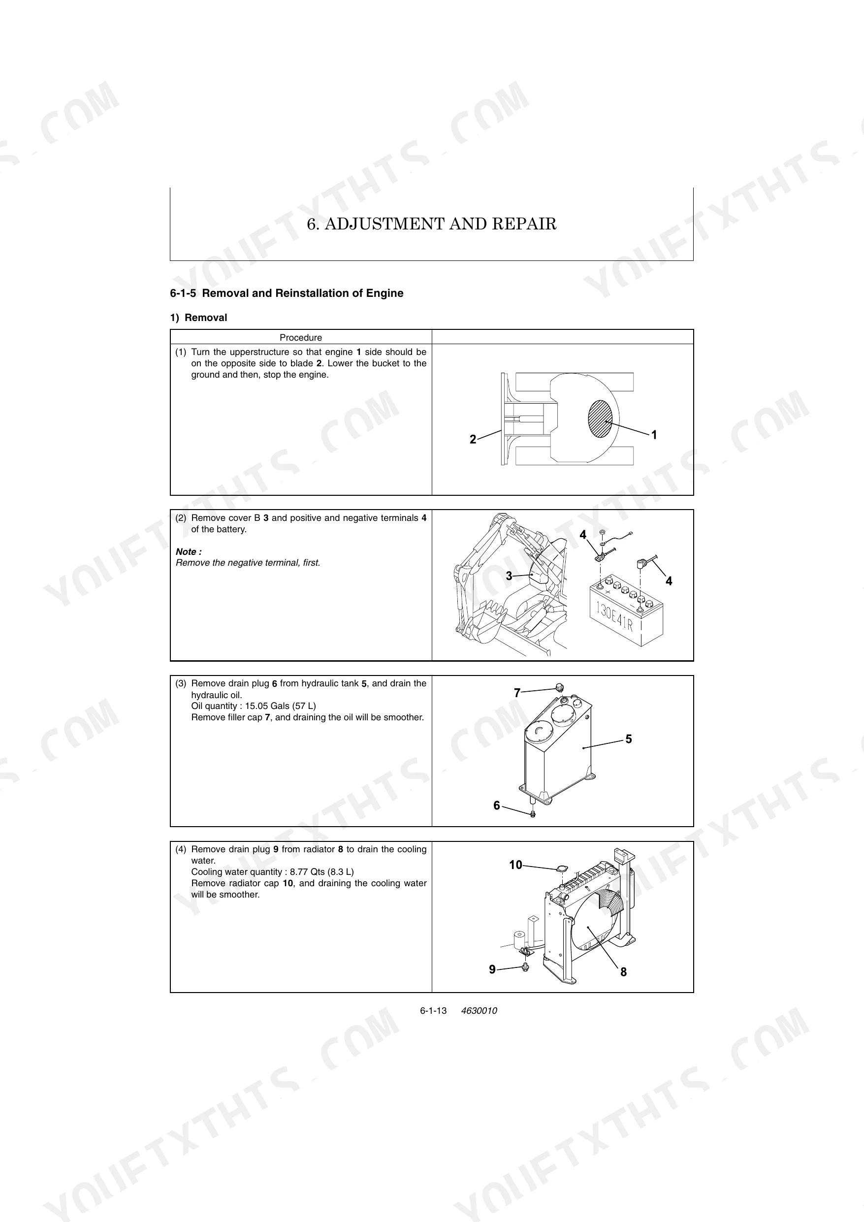
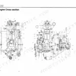
| Adjustment and Repair | 265-368 | Electric Equipment of the Machine (Parts Layout of Electrical Equipment, Monitor and Alarm Systems, Wiring Diagram, Stop Motor Operation, Removal and Reinstallation of Engine, Removal and Reassembly of Starter Motor) |
| Periodic Inspection and Servicing | 369-371 | List of Periodic Inspection and Servicing |
| Fuel, Lube Oil and Grease Recommended | 372-373 | Fuel, Engine Oil, Hydraulic Oil, Swing Reduction Gear Oil, Travel Reduction Gear Oil, Cooling Water |
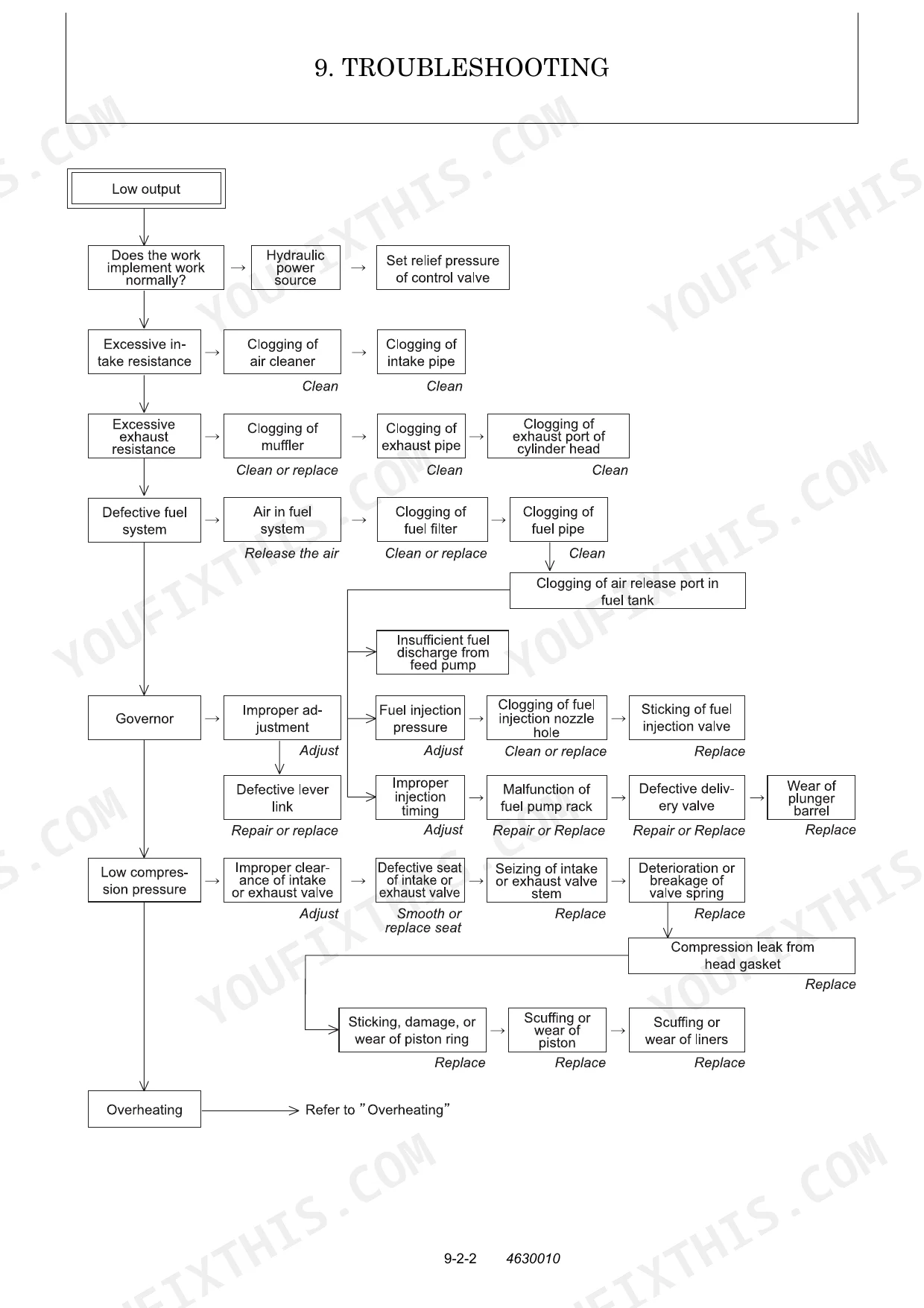
| Troubleshooting | 374-530 | Non-Breakdowns (Natural Release of Bucket, Discontinuous Arm Movement, Drifting of Upperstructure on Quick Travel Operation, Thermal Shock of Travel Motor) |
Quick Reference Specifications
| Specification | Value | Page |
|---|---|---|
| Bleeder valve hose inside diameter | 0.20 in. (5 mm) | p. 18 |
| Bleeder valve tightening torque | 3.61 to 5.06 ft·lbf (4.9 to 6.7 N·m) | p. 18 |
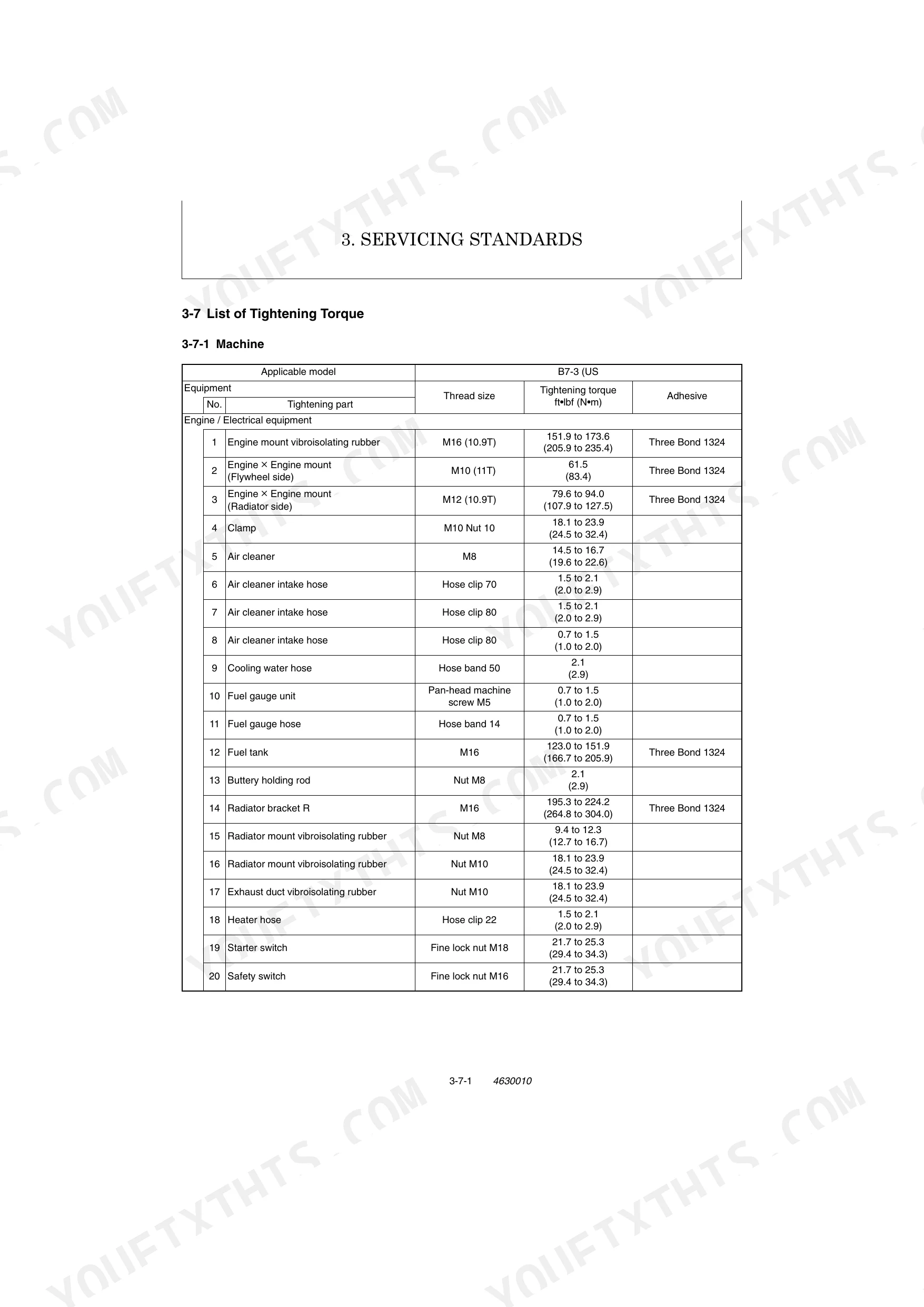
| Pipe joint bolt M8 tightening torque | 9.40 to 12.32 ft•lbf (12.7 to 16.7 N•m) | p. 52 |
| Pipe joint bolt M12 tightening torque | 18.07 to 25.30 ft•lbf (24.5 to 34.3 N•m) | p. 52 |
| Hydraulic pump piping tightening torque | 3.62 to 4.34 ft•lbf (4.9 to 5.9 N•m) | p. 338 |
| Pilot control piping tightening torque | 2.89 to 3.62 ft•lbf (3.9 to 4.9 N•m) | p. 342 |
| System relief set pressure (Piston pump P1) | 3552.5 PSI (24.5 MPa) | p. 87 |
| System relief set pressure (Piston pump P2) | 3552.5 PSI (24.5 MPa) | p. 87 |
| Swing motor case pressure (maximum) | 42.7 PSI (0.29 MPa) | p. 225 |
| Bleeder valve tightening torque (hydraulic pump air release) | 3.61 to 5.06 ft·lbf (4.9 to 6.7 N·m) | p. 18 |
| System relief set pressure (Gear pump P3) | 2987.0 PSI (20.6 MPa) | p. 87 |
| Engine Oil Capacity | 10.78 Qts. (10.2 L) | p. 373 |
Yanmar B7-3(US) Common Problems This Manual Covers
Yanmar B7-3 hydraulic pump making grinding noise, boom and bucket slow to respond
Check hydraulic oil level first; the tank holds 15.05 Gals. (57 L) per page 373. Inspect the suction strainer for blockage and look for foamy oil, which signals aeration. Verify system relief pressure reaches 3552.5 PSI (24.5 MPa) per page 87. Persistent noise after refilling points to internal pump wear.
Manual Section: Hydraulic Pump Troubleshooting p. 87Hydraulic functions slow, weak, or erratic immediately after hose replacement or pump service
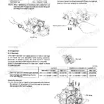
Bleed air from the hydraulic pump using the bleeder valve procedure on page 18. Attach a hose with 0.20 in. (5 mm) inside diameter to the bleeder, then torque the valve to 3.61 to 5.06 ft·lbf (4.9 to 6.7 N·m) after bleeding. Cycle all implements through full range ten times to purge remaining air.
Manual Section: General Cautions for Maintenance Work p. 18Hydraulic oil leaking at cylinder or hose fittings after seal kit installation
Inspect all disturbed fittings for twisted or pinched O-rings before torquing. Torque M12 pipe joint bolts to 18.07 to 25.30 ft•lbf (24.5 to 34.3 N•m) per page 52; hydraulic pump piping connections torque to 3.62 to 4.34 ft•lbf (4.9 to 5.9 N•m) per page 338. Never reuse seals removed during disassembly.
Manual Section: Hydraulic Equipment p. 52Upperstructure swing drifts or won't hold position after swing motor service
Verify swing motor case drain pressure stays below 42.7 PSI (0.29 MPa) per page 225; higher case pressure indicates internal bypass. Inspect the swing brake valve: set pressure should be 2987 PSI (20.6 MPa) per page 89. Check that all swing motor hose fittings are fully torqued and free of air.
Manual Section: Swing Motor Troubleshooting p. 225Boom or arm drifts down with spool in neutral after control valve service
Remove the control valve and inspect each spool bore for contamination; even fine debris prevents neutral return. Torque all system and circuit relief valves to 20.3 to 23.1 ft•lbf (27.5 to 31.4 N•m) per page 180. Follow disassembly cleanliness procedures on page 7 and flush all passages before assembly.
Manual Section: Control Valve Troubleshooting p. 180Engine cranks slowly or won't start, battery charge alarm lamp illuminated on panel
Check battery electrolyte and load-test it. A failed cell drags cranking amps even when terminal voltage reads 12V. Inspect the battery charge warning circuit per . After any charging system repair, confirm idle speed holds 1125 to 1175 RPM (low) and 2075 to 2125 RPM (high) per page 523.
Manual Section: Electrical Equipment on Panel TroubleshootingFrequently Asked Questions
What do I get after purchasing this Yanmar B7-3(US) manual?
A 530-page Service Manual in searchable PDF format (79 MB), available the moment you complete checkout. View on computer, tablet, or phone, with no shipping wait.
Am I able to print pages from this Yanmar B7-3(US) manual?
No restrictions at all. Print individual pages, full chapters, or the entire manual. The PDF is completely unlocked.
Are hydraulic system diagrams in this Yanmar B7-3(US) Service Manual?
Yes, complete hydraulic schematics with flow diagrams, valve configurations, and pressure specifications are included.


Reviews
There are no reviews yet.