


Part of the Yanmar Repair Manuals.
All 1,001 pages of this Yanmar EA2400 3TNV72-YUKS Technical Manual (OEM #0BTNV-U00300) exist for one purpose: giving you the factory-accurate procedures to keep your 2005-2007 diesel tractor running right. Inside, you get complete wiring diagrams with full circuit diagnosis, hydraulic schematics tracing every fluid path from the HST to implement circuits, and a troubleshooting section that points to root causes, not guesses. Torque tables, exploded views, and detailed engine rebuild procedures, from fuel system to crankshaft, fill the remaining pages. Set the M10 HST link adjustment bolt to 33-43 ft-lbs (44-59 N-m) and verify implement side pressure at 1,679-1,892 psi (11.6-13 MPa) at 3,300 rpm engine speed. Your tractor is down. One PDF gives you the right number the first time. Bookmarked by section; search any spec by keyword, open it on your phone, and start turning wrenches.
What's Inside This Yanmar EA2400 Manual
| System | Pages | Key Topics |
|---|---|---|
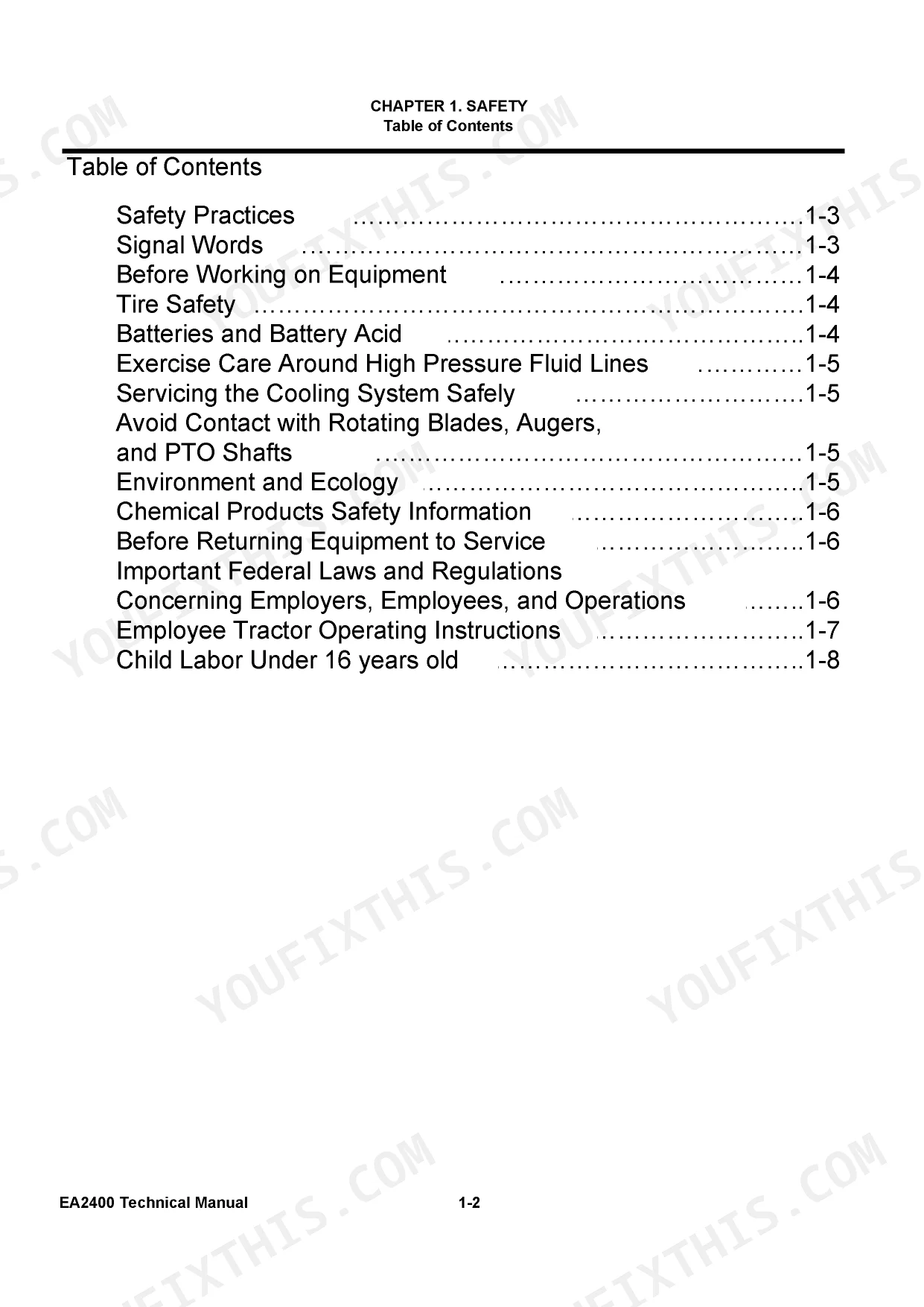
| Safety | 3-9 | Safety Practices, Signal Words, Before Working on Equipment, Tire Safety, Batteries and Battery Acid, Exercise Care Around High Pressure Fluid Lines |
| Introduction | 10-19 | Shop Handbook Intent and Use, Engine, Hydro-Static Transmission, Fasteners, Assembly Procedure, Tractor, Fluids and Lubricants, Torque Tables |
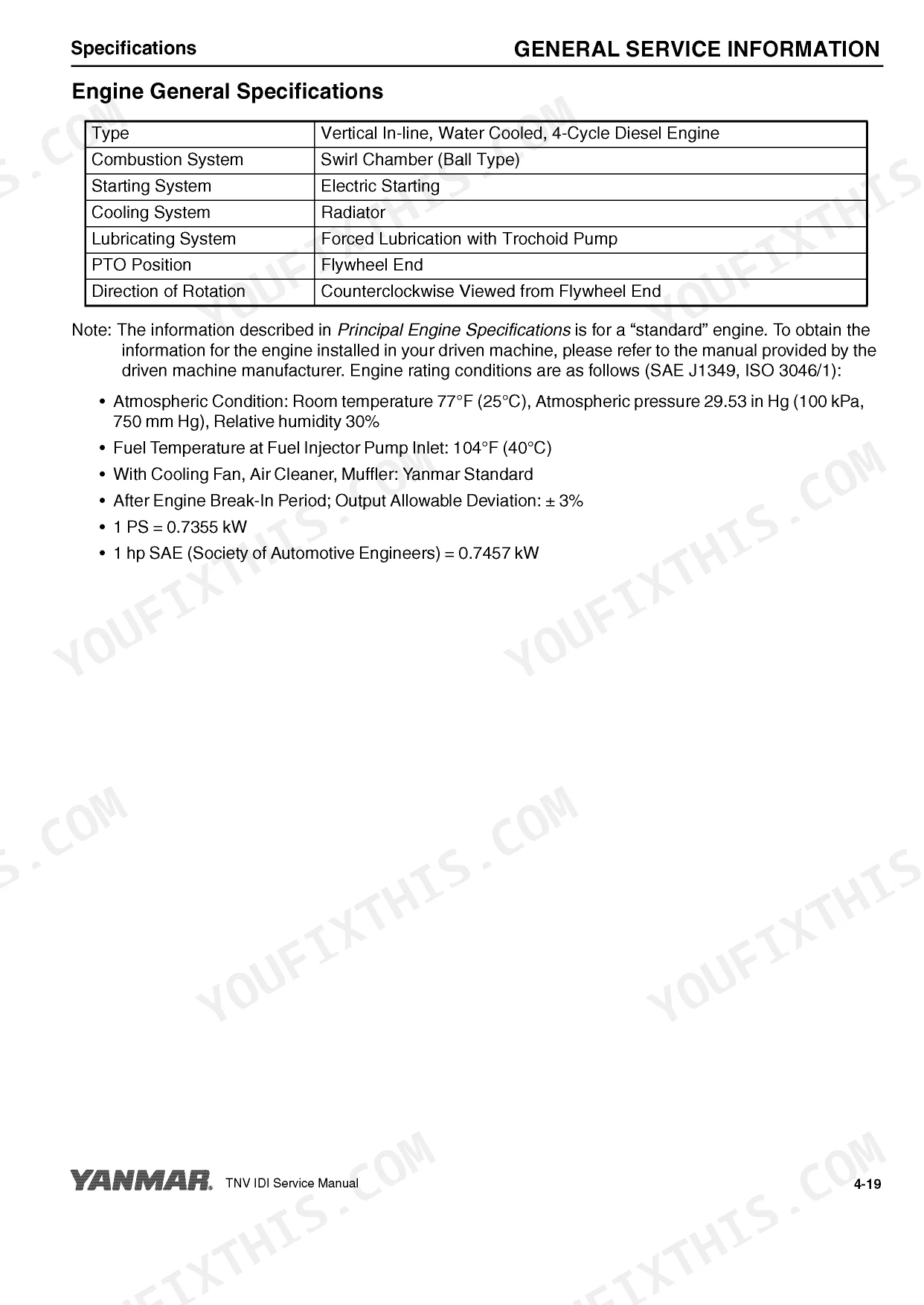
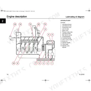
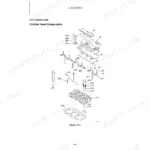
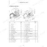
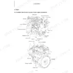
| Engine | 20-302 | Fuel System, Cooling System, Lubrication System, Cylinder Head, Crankshaft and Pistons, Starter Motor |
| Electrical Section Overview | 304 | Electrical Diagram Index, Circuit Reference Guide, Component Locator Index, System Component Index, Wiring Diagram List |
| General Information | 305-306 | 1-1 Electrical Diagram Information, 1-2 Circuit Diagnosis Information, 1-3 Common Circuit Tests |
| Electrical System Specifications | 307 | Battery Specifications, Alternator Output Specs, Starter Motor Ratings, Fuse and Relay Ratings, Wire Color Codes |
| Component Location | 308-309 | Alternator Location, Starter Motor Location, Fuse Box Location, Relay Location, Sensor Locations |
| System Component | 310 | Alternator Assembly, Starter Motor Components, Relay Components, Fuse Block Assembly |
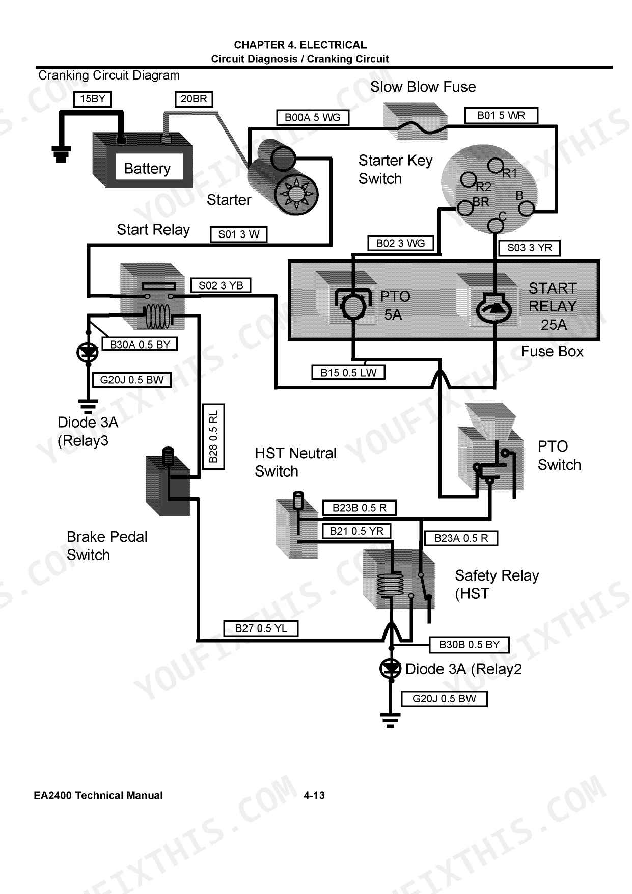
| Circuit Diagnosis | 311-363 | 5-1 Cranking Circuit Diagnosis, 5-2 Charging Circuit Diagnosis, 5-3 Preheating Circuit Diagnosis, 5-4 Fuel Supply and Stop Circuit Diagnosis, 5-5 Instrument Panel Circuit Diagnosis, 5-6 Light Circuit Diagnosis, 5-7 PTO Stop Circuit Diagnosis |
| Diagnosis and Replacement Work for Electrical Components | 364-1001 | 6-1 General, 6-2 Engine, 6-3 Charging, 6-4 Light |
Quick Reference Specifications
| Specification | Value | Page |
|---|---|---|
| Suction Filter Size | 10 MICRON | p. 390 |
| Battery Voltage | 12 V | p. 307 |
| Alternator Regulated Voltage | 14.2 - 14.8 V | p. 307 |
| Hydro Static Transmission Link Adjustment (M10 bolt) | 33 to 43 ft-lbs (44 to 59 N-m) | p. 415 |
| Implement Side Pressure (Engine Speed 3300 rpm) | 1679-1892 psi (11.6-13 MPa) | p. 996 |
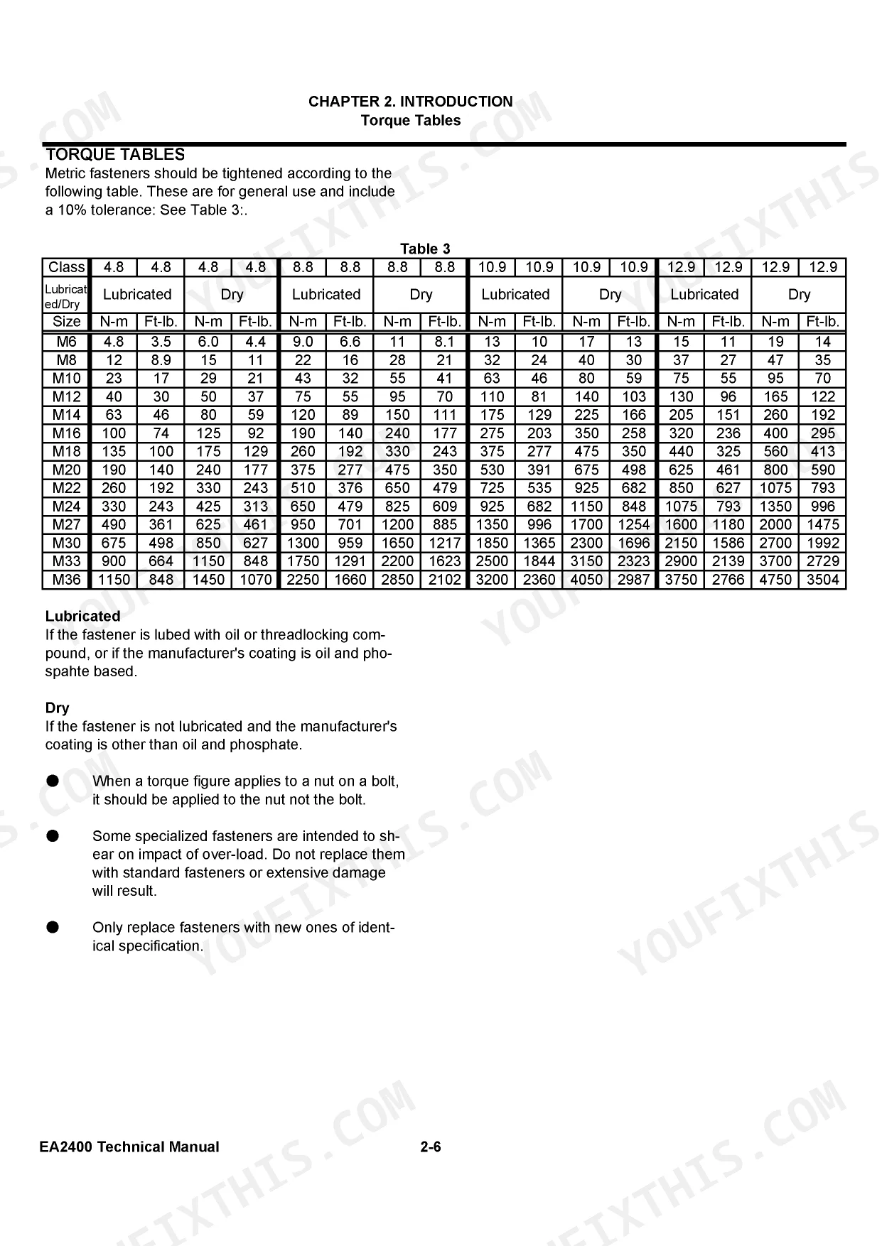
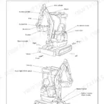
| Engine Mount Bolts Torque | 32.5 to 43.5 ft-lbs (44 to 59 N-m) | p. 809 |
Yanmar EA2400 Common Problems This Manual Covers
Yanmar EA2400 tractor clicks when turning the key but starter motor refuses to crank over.
Test the battery at the terminals using a multimeter. Verify the resting voltage reads exactly 12 V as specified on page 307. If voltage drops significantly under load, clean the connections. Replace the battery if it fails to hold a charge during the cranking cycle.
Manual Section: Electrical Cranking Circuit Diagnosis p. 307Loader lift cylinder moves slowly or completely stalls out when lifting heavy dirt loads.
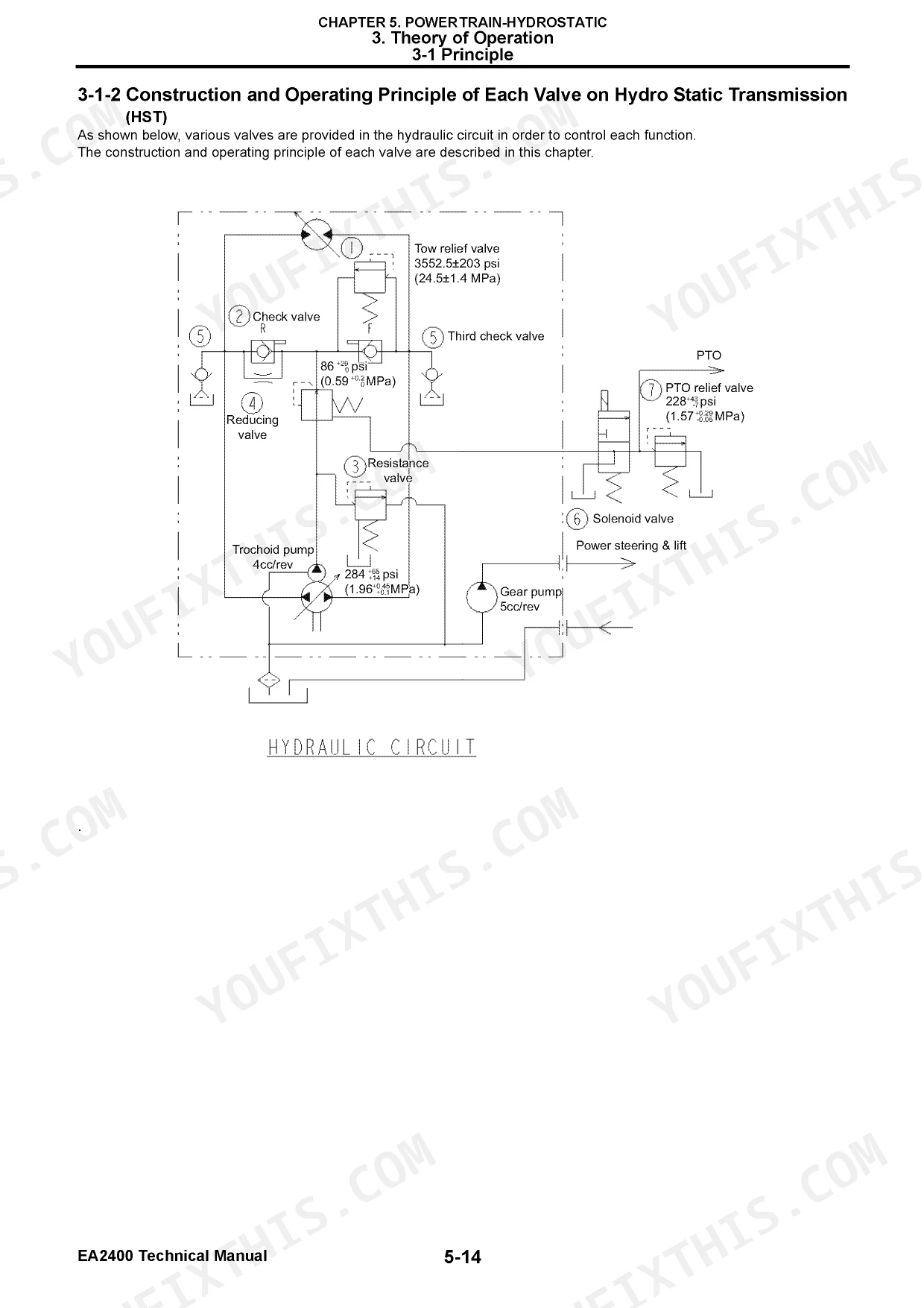
Check the implement side pressure while running the engine at 3300 rpm. Measure the pressure at the test port to confirm it reaches 1679-1892 psi (11.6-13 MPa). If the pressure falls below this range, inspect the 10 MICRON suction filter on page 390 and clean the implement control valve.
Manual Section: Hydraulic Implement Control Valve Diagnostics p. 996Hydrostatic transmission slips under load or pedals feel extremely heavy during forward and reverse travel.
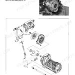
Inspect the hydro-static transmission linkage for binding or excessive play. Adjust the M10 link bolt and torque it to 33 to 43 ft-lbs (44 to 59 N-m) as shown on page 415. Check the fluid level and verify the forward and reverse drive pedal moves freely without sticking.
Manual Section: Hydro-Static Transmission Troubleshooting (HST) p. 415Engine vibrates excessively at idle and sends a loud knocking noise through the tractor frame.
Inspect the engine mount brackets for cracked metal or loose hardware. Tighten all mounting bolts and torque the M10 x 20 mm fasteners to 32.5 to 43.5 ft-lbs (44 to 59 N-m) using the specifications on page 809. Replace any crushed rubber isolators before returning the machine to service.
Manual Section: Engine System Troubleshooting p. 809Frequently Asked Questions
What are the torque specs for the wheel lug nuts?
The wheel lug nuts (referred to as 7/16 - 20 UNF bolts) for both the front and rear tires should be torqued to 51.6 to 59.0 ft-lbs (70 to 80 N•m) during installation. This information can be found on page 10-63 for front tires and page 10-71 for rear tires. p. 700
How quickly can I access this Yanmar EA2400, 3TNV72-YUKS manual after buying?
Instant PDF download (63 MB). You get the full 1001-page searchable TECHNICAL MANUAL immediately after payment. Open it on your laptop, tablet, or phone right in the shop.
Am I able to print pages from this Yanmar EA2400, 3TNV72-YUKS manual?
Yes, print as many copies as you want, and there are no restrictions. Many mechanics print the section they need and bring it to the shop floor.
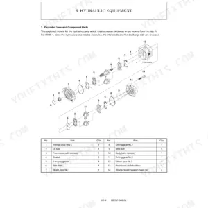
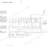
Does this Yanmar EA2400, 3TNV72-YUKS manual include hydraulic schematics?
Yes. The manual includes a hydraulic system diagram covering the main circuits.
Reviews
There are no reviews yet.