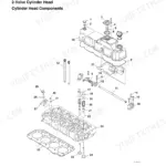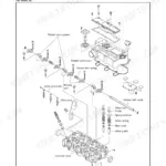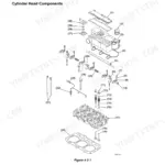


Part of the Yanmar Repair Manuals.
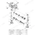
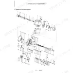
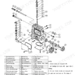
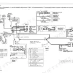
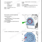
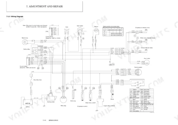
All 352 pages of this Yanmar SV08-1A Service Manual are built around one goal: giving you factory-level access to every system on this compact excavator. Inside, you get hydraulic circuit schematics with full pressure-adjustment procedures, wiring diagrams for the complete electrical system, and exploded-view drawings of the hydraulic pump, control valve, swing motor, and travel motor. Packed alongside are page after page of torque specifications, a full troubleshooting section covering non-breakdown symptoms and component-level faults, and complete engine procedures from crankshaft teardown to final reassembly. After any hydraulic work, bleed at low idle: cycle each cylinder 50 to 100 mm from stroke end four or five times, then run full strokes to purge air. Every hour your machine sits costs money. Grab this Yanmar SV08-1A service manual PDF, search by keyword, jump to any bookmarked section, and get back to digging.
Complete the set for your SV08-1A
- Parts Catalog: Yanmar SV08-1A Parts Catalog (incl. Wiring)
What's Inside This Manual
| System | Pages | Key Topics |
|---|---|---|
| General Cautions for Maintenance Work | 11-24 | Correct Work, Safety Precautions, Preparations, Cautions for Disassembly and Reassembly, Cautions for Removal and Installation of Hydraulic Equipment |
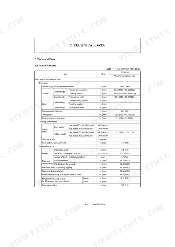
| Technical Data | 25-38 | 2-1 Specifications, 2-2 Outline Drawing and Working Area, 2-3 Weight List of Main Parts, 2-4 Lifting Capacity List |
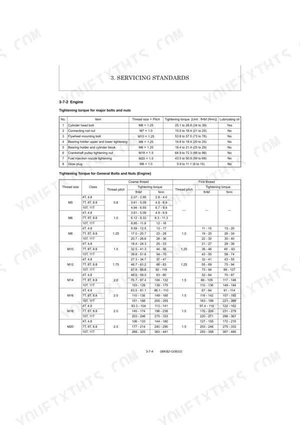
| Service Standards | 39-62 | Machine Performance, Engine, Undercarriage (Rubber Crawler Specifications), Controls, Hydraulic Equipment (Hydraulic Cylinders) |
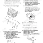
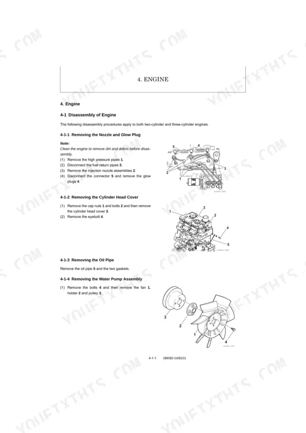
| Engine | 63-106 | Disassembly of Engine (Removing: Nozzle and Glow Plug, Cylinder Head Cover, Oil Pipe, Water Pump Assembly, Rocker Arm and Push Rods, Exhaust Manifold, Cylinder Head, Tappets, Injection Pump Assembly, Crankshaft Pulley, Timing Gear Case Assembly, Idle Gear and Oil Pump Assembly, Camshaft Assembly, Suction Filter and Pipe, Connecting Rods and Pistons, Crankshaft Assembly) |
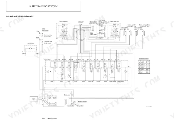
| Hydraulic System | 107-140 | 5-1 Outline, 5-2 Hydraulic Circuit Schematic, 5-3 Circuit Operation, 5-4 Pressure Adjustment |
| Hydraulic Equipment | 141-234 | 6-1 Hydraulic Pump, 6-2 Control Valve, 6-3 Swing Motor, 6-4 Valve Block, 6-5 Travel Motor |
| Adjustment and Repair | 235-310 | 7-1 Electrical Equipment of Machine, 7-2 Undercarriage, 7-3 Controls, 7-4 Swing Bearing, 7-5 Hydraulic Equipment, 7-6 ROPS Bar, 7-7 Work Implements |
| Periodic Inspection and Servicing | 311-314 | 8-1 List of Periodic Inspection and Servicing |
| Fuel, Lube Oil and Grease Recommended | 315-318 | Engine Oil, Travel Reduction Gear Oil, Hydraulic Oil, Fuel, Engine Cooling Water, Anti-Freeze Mixing Ratio |
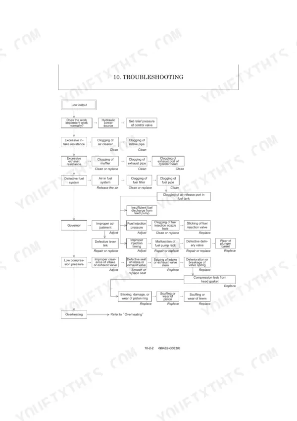
| Troubleshooting | 319-350 | 10-1 Non-Breakdowns, 10-2 Troubleshooting |
| Reference Data | 351-352 | 11-1 Dimensions and Specifications for Attachment |
Quick Reference Specifications
| Specification | Value | Page |
|---|---|---|
| Hydraulic system air release procedure | 1. Run the engine at medium speed and activate the respective circuits for about 10 to 15 minutes. 2. For Hydraulic Cylinders: 1) Set the Engine Speed at Low Idling Range. 2) Extend and Retract the Cylinder Up to 1.97 to 3.9 in. (50 to 100 mm) from Each Stroke End Slowly 4 or 5 Times. (Note: The extension and retraction stroke is up to 1.97 in. (50 mm) from each stroke end for the blade cylinder.) 3) Then, Fully Extend and Retract the Cylinder 3 or 4 Times. | p. 21 |
| Fuse quantity | 10 x 2 Apcs. | p. 32 |
| Slow blow fuse rating | 40A | p. 235 |
| Battery type | 44B-19L | p. 31 |
| Battery voltage - 5 hrs rate capacity | 12-30 V-Ah | p. 31 |
| Hydraulic oil type | YANMAR SUPER HYDRO. OIL (ISO VG46) | p. 315 |
| Hydraulic oil system prescribed amount (In the tank) | 1.74 Gals. (6.6 L) | p. 315 |
| Engine cooling water type | YANMAR genuine long-life coolant (LLC) 51% added water | p. 315 |
| Cooling system radiator capacity | 1.69 Qts. (1.6 L) | p. 315 |
| Radiator hose band 35 tightening torque | 1.8 to 2.2 ft·lbf (2.45 to 2.94 N·m) | p. 54 |
| Radiator hose clip 25 tightening torque | 1.8 to 2.2 ft·lbf (2.45 to 2.94 N·m) | p. 54 |
| Engine mount L, R tightening torque (M10 x 25) | 32.5 to 43.4 ft·lbf (44.1 to 58.9 N·m) | p. 54 |