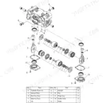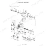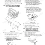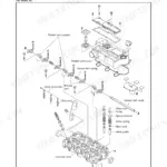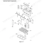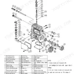


Part of the Yanmar Repair Manuals.
Put a pressure gauge on the main relief port and the spec you are testing against is right there: 24.5 MPa, with the adjustment procedure in the Pressure Adjustment section if the reading is off. That is what this book is for, the factory service manual for the Yanmar ViO50-6A crawler excavator and its 4TNV88-ZPBV diesel, publication MMB34ENMA00101, delivered as a 663-page PDF download.
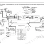
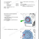
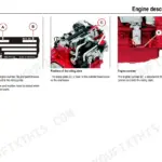
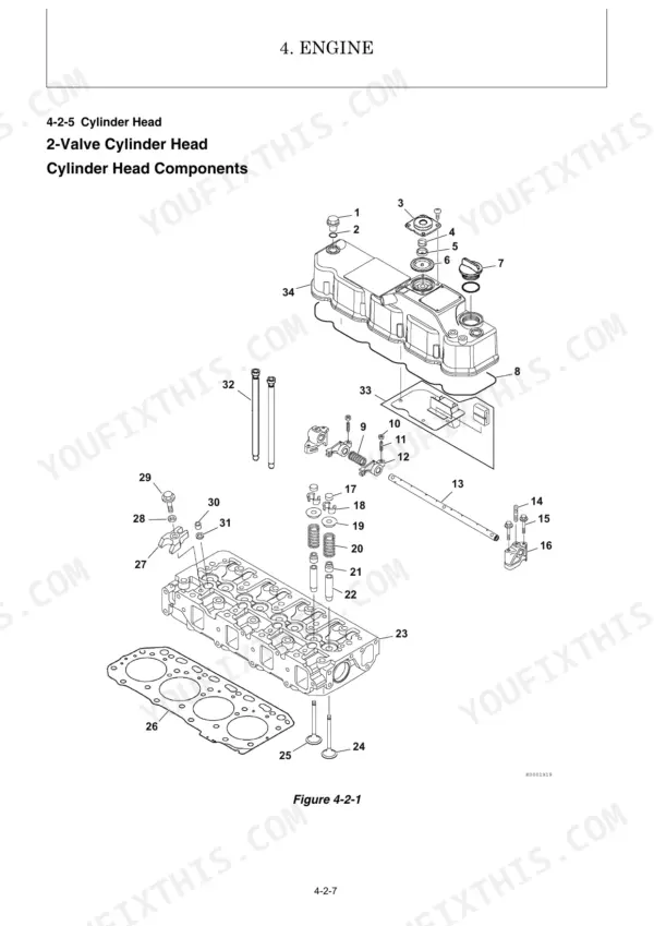
Coverage runs from engine work (cylinder head, valve clearance, fuel injection pump, injectors, coolant pump) through the electrical system with wiring diagrams, an error code list, and monitor and alarm troubleshooting, to the hydraulics: control valve operation, swing motor, pressure adjustment, and removal and reinstallation of the pump, pilot valves, cabin, and air conditioner.
When the machine is down and there is nobody on the radio who knows it better than you, this is the book that gets it tracking and digging again.
Complete the set for your ViO50-6A
- Parts Catalog: Yanmar ViO50-6A Parts Catalog (Excavator)
What's Inside This Manual
| System | Pages | Key Topics |
|---|---|---|
| 2-5 Specifications for Attachment | 15 | |
| 2-6 Periodic Inspection and Servicing | 15 | |
| 2-7 Fuel, Lube Oil and Grease Recommended | 15 | |
| 2-8 Hydraulic Circuit Schematic | 15 | |
| 2-9 Wiring Diagram | 16-39 | Nominal and Allowable Values, Test and Adjustment Specifications, Rubber Crawler Specifications, Steel Crawler Specifications, Common Specifications of Steel & Rubber Crawlers |
| 3-8 Pressure Adjustment | 40-72 | Relief Valves, Swing Brake Valve, Cut-Off Valve, Safety Statements, Safety Precautions, Before You Begin Servicing, Introduction, Special Service Tools |
| 4-6 Starter Motor | 73 | |
| 4-7 Alternator | 73 | |
| 4-8 Electronic Control System | 73 | Before You Begin Servicing |
| 4-9 Electric Wiring | 73 | Electric Wiring Precautions |
| 4-10 Failure Diagnosis | 73 | Special Service Tools, Troubleshooting by Measuring Compression Pressure |
| 4-11 Troubleshooting | 74-244 | Quick Reference Table for Troubleshooting, Parts Layout of Electrical Equipment, LCD Monitor and Alarm Systems, Engine ECU, Circuit Description of Auto Deceleration Mode |
| 5-4 Error Code List | 245-252 | Control Valve Operation, Additional Operation of Control Valve, Boom, Arm, Bucket, Swing, Boom Swing, Blade |
| 6-6 Swing Motor | 253 | |
| 6-8 Proportional Solenoid Valve for P.T.O | 254-489 | 6-1-1 Control Valve Operation, 6-1-2 Additional Operation of Control Valve, 6-2-1 Boom, 6-2-2 Arm |
| 7-7 Cabin | 489 | Removal and Reinstallation of Cabin, Disassembly and Reassembly of Cabin |
| 7-8 Air Conditioner | 490 | 7-1-1 Removal and Reinstallation of Engine, 7-1-2 Removal and Reinstallation of Starter Motor, 7-1-3 Removal and Reinstallation of Radiator and Oil Cooler |
| 7-5 Hydraulic Equipment | 489 |
Quick Reference Specifications
| Specification | Value | Page |
|---|---|---|
| Sprocket mounting bolt (M14) tightening torque | 127 to 149 N·m | p. 60 |
| Idler seal cover mounting bolt (M12) tightening torque | 79 to 93 N·m | p. 60 |
| Boom fulcrum pin lock plate (M14 x 35) tightening torque | 127 to 149 N·m | p. 62 |
| Arm fulcrum pin lock plate (M14 x 25) tightening torque | 127 to 149 N·m | p. 62 |
| Engine Oil Capacity | 7.4 L | p. 33 |
| Hydraulic Oil Tank Capacity | 38.0 L | p. 33 |
| Fuel Tank Capacity | 66.0 L | p. 33 |
| Rated Output / Engine Speed (GROSS) | 29.6/2400 kW/rpm | p. 22 |
| Maximum Torque / Engine Speed | 131.4 to 143/1440 N•m/rpm | p. 23 |
| System Relief Set Pressure (P1, P2) | 24.5 MPa | p. 19 |
| Swing Brake Valve Set Pressure | 21.6 MPa | p. 71 |
| Cylinder Head Bolt Tightening Torque | 85.3 to 91.1 N•m | p. 64 |