


Part of the Yanmar Repair Manuals.
Whether you are pulling the turbocharger or rebuilding the bottom end, this 100-page Yanmar 4jh3-te, 4jh3-hte, 4jh3-dte service manual pdf (OEM #HINSHI-H10-009) lays out the complete factory teardown steps for your marine diesel engine. You get thorough overhaul instructions for the cylinder block, fuel injection pump, and sea water cooling system, plus dedicated troubleshooting charts for uneven cylinder output and knocking. Open up the electrical section to trace faults using the factory wiring diagrams, or follow the step-by-step rebuilding guides for the gear train and piston assemblies. Confirm your injectors are running the correct YDLLA-P nozzle type with a 150° hole angle, and lock down the cylinder head bolts in two steps, finishing at 9.3±0.3 kgf·m. Don't let a mystery fuel issue keep your boat tied to the dock. Grab this bookmarked digital file, load it onto your shop tablet, and start turning wrenches.
What's Inside This Yanmar 4JH3 Series Manual
| System | Pages | Key Topics |
|---|---|---|
| 1. to Perform Service Safely | 6-11 | Warning Symbols, Safety Precautions, Location of Product Safety Labels |
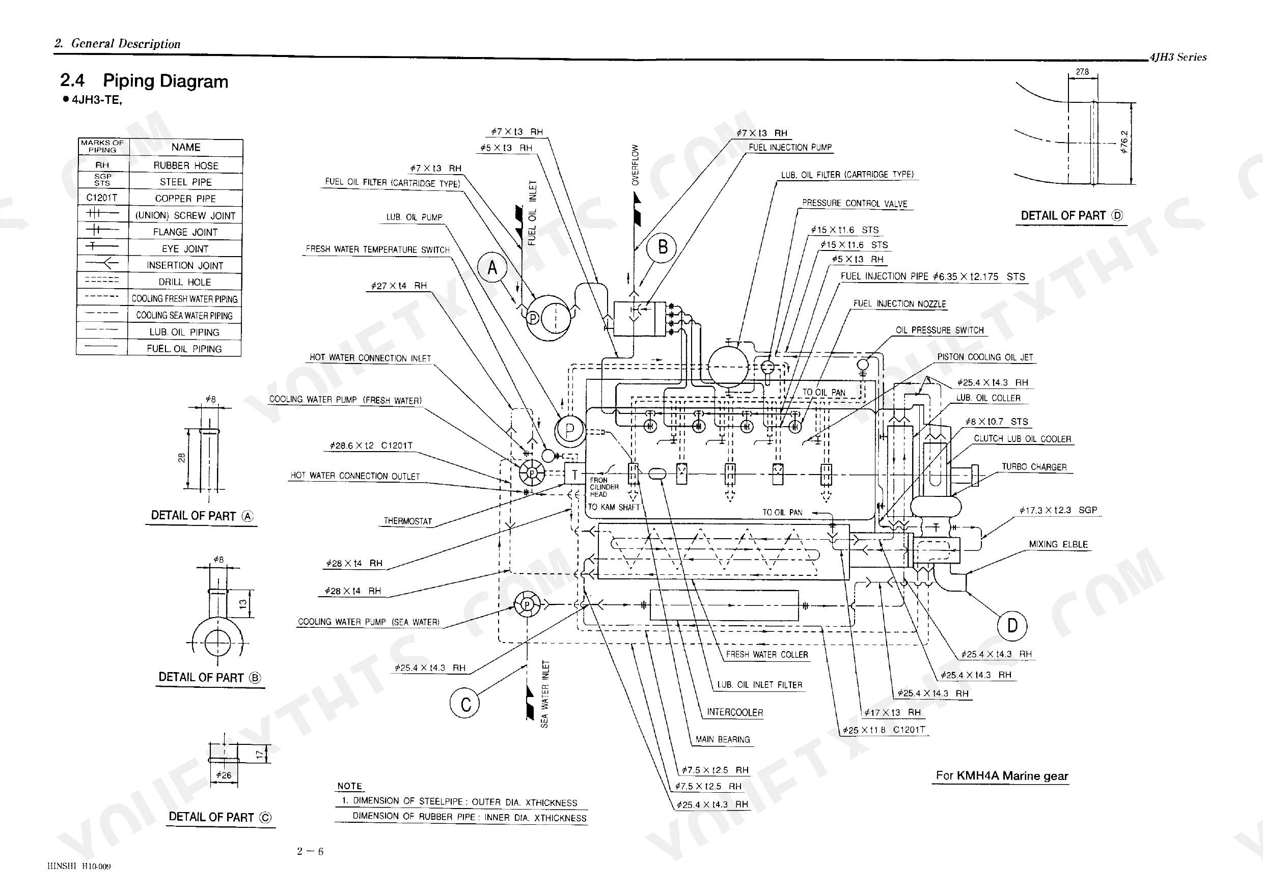
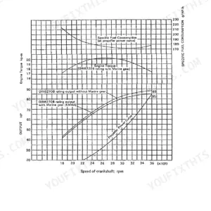
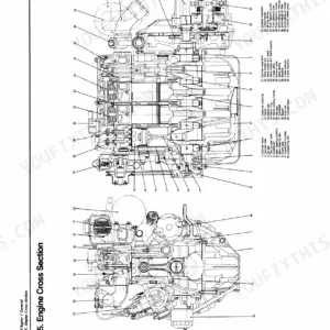
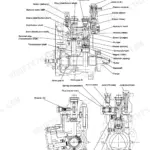
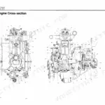
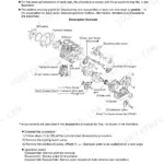
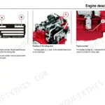
| General Description | 12-25 | Principal Particulars, Appearance and Names of Parts, Cross-Sectional Drawing, Piping Diagram, Performance Curves, Front Power Take-Off, Fuel Oil, Lube Oil |
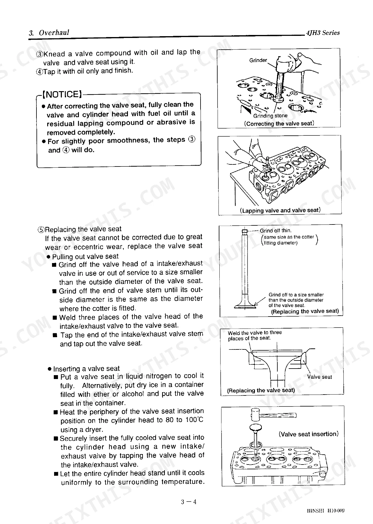
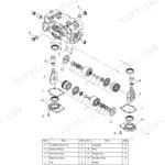
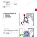
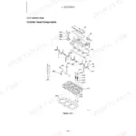
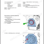
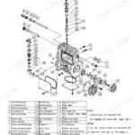
| Overhaul | 26-75 | Cylinder Head, Combustion Surface, Valve Seat, Suction/Exhaust Valve and Valve Guide, Valve Spring, Valve Arm and Push Rod, Installing the Cylinder Head, Piston |
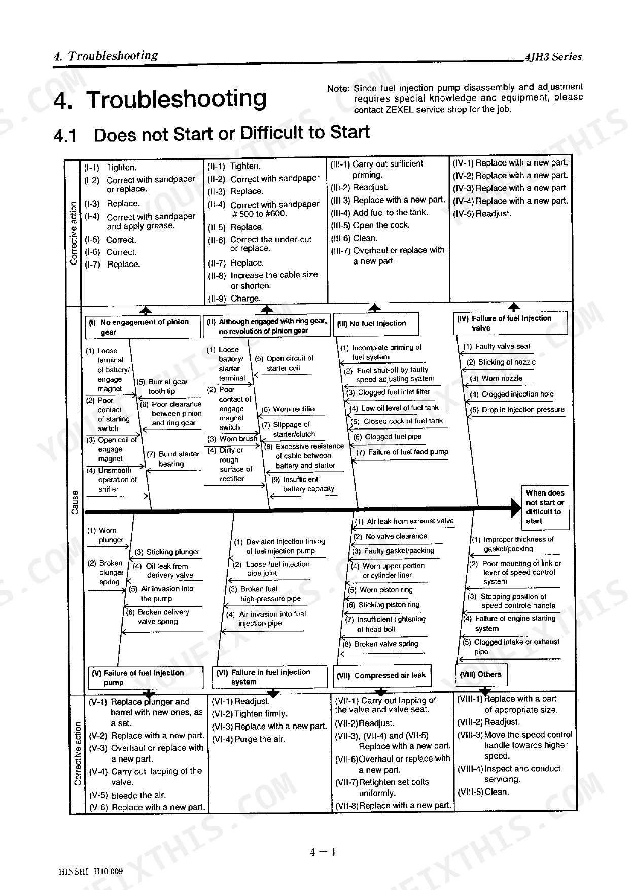
| Troubleshooting | 76-84 | Does Not Start or Difficult to Start, Unsmooth Revolution, Sudden Engine Stop, Poor Exhaust Gas Color, Insufficient Output, Uneven Cylinder Outputs, Knocking |
| Periodic Checking List | 85 | Fuel Oil Check and Supply, Lube Oil Check and Replacement, Marine Gear Oil Check and Replacement, Cooling Water System Check, Electrical Components Check |
| Tool and Measuring Instrument | 86-88 | Tool, Measuring Instrument |
| Service Specifications | 89-96 | Engine Adjusting Standards, Service Standards |
| Instrument Panel(Option) | 97-100 | - |
Quick Reference Specifications
| Specification | Value | Page |
|---|---|---|
| All Models | ||
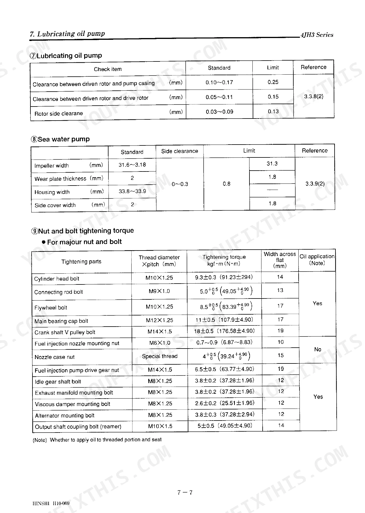
| Cylinder head bolt tightening torque (First step) | 5 kgf·m | p. 32 |
| Cylinder head bolt tightening torque (Second step) | 9.3±0.3 kgf·m (91.4±0.94 N·m) | p. 32 |
| Nozzle type | YDLLA-P | p. 63 |
| Hole angle | 150° | p. 63 |
| Fuel filter water alarm activation level | On at the water level of 23 mm (80cm³) or more | p. 89 |
| Turbocharger model | RHB52W (IHI) | p. 72 |
| Turbine shaft end nut tightening torque | 20±2 kgf·cm (196±19 N·cm) | p. 72 |
| Fuel feed pump type | Vane type (built-in) | p. 55 |
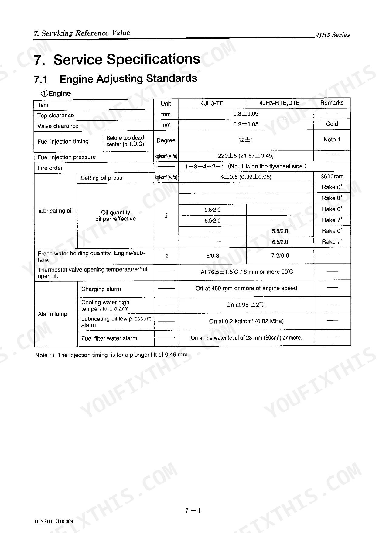
| Top clearance | 0.8±0.09 mm | p. 89 |
| Valve clearance | 0.2±0.05 mm | p. 89 |
| 4JH3-TE | ||
| Number of nozzle holes hole diameter | 5-φ0.23 mm | p. 63 |
| 4JH3-HTE,DTE | ||
| Number of nozzle holes hole diameter | 5-φ0.25 mm | p. 63 |
Yanmar 4JH3 Series Common Problems This Manual Covers
Yanmar 4JH3-TE engine fails to reach rated wide-open-throttle RPM under heavy load conditions.
Inspect the turbocharger and intake system for restrictions. Check the RHB52W turbine shaft end play on page 73, ensuring it measures within the 0.03 to 0.06 mm service standard. Clean the air filter and verify the exhaust mixing elbow is not clogged with carbon.
Manual Section: 3. Overhaul p. 73Heavy blue smoke blowing from the exhaust manifold at higher operating temperatures.
Check the engine oil level to ensure it does not exceed the 5.8 L pan capacity. Inspect the crankcase breather hose for oil saturation. Verify valve clearance is exactly 0.2±0.05 mm as outlined on page 89. Replace the valve stem seals if clearance is correct but smoke persists.
Manual Section: 7. Service Specifications p. 89Engine suddenly dies at idle or starves for fuel when fed from an external clean supply.
Inspect the built-in vane type fuel feed pump on page 55 for internal wear or sticking vanes. Drain the fuel filter housing if the water alarm activates at the 23 mm level shown on page 89. Bleed all low-pressure fuel lines and verify there are no suction side air leaks.
Manual Section: 3. Overhaul p. 55Thick black exhaust smoke and poor combustion symptoms when operating under heavy load.
Remove and test the YDLLA-P fuel injectors. Verify the injection nozzle opening pressure measures exactly 220±5 kgf/cm² as specified on page 63. Clean the nozzles and inspect the turbocharger wastegate for sticking. Torque the nozzle mounting nuts to 0.7~0.9 kgf·m using the specs on page 95.
Manual Section: 3. Overhaul p. 63Frequently Asked Questions
What are the torque specs for the Yanmar 4JH3-series cylinder head, rocker cover, and injection components?
The cylinder head bolts should be tightened in two steps: first to 5 N·m, then to 9.3±0.3 (91.4±0.94) N·m. This procedure is detailed in section 3.3.1 (6) "Installing the cylinder head" on page 32, and the specific torque is also listed in section 9 "Nut and bolt tightening torque" on page 95 for M10×1.25 bolts. The fuel injection nozzle mounting nut should be tightened to 0.7~0.9 kgf·m (6.87~8.82 N·m), as specified in section 3.3.10 (3) "Installing the fuel injection nozzle" on page 65 and section 9 "Nut and bolt tightening torque" on page 95 for M6×1.0 bolts. Torque specifications for the rocker cover were not found in the manual. p. 32
How quickly can I access this Yanmar 4JH3-TE, 4JH3-HTE, 4JH3-DTE manual after?
Instant PDF download (2 MB). You get the full 100-page searchable Service Manual immediately after payment. Open it on your laptop, tablet, or phone right in the shop.
Am I able to print pages from this Yanmar 4JH3-TE, 4JH3-HTE, 4JH3-DTE manual?
Yes. The PDF has no DRM restrictions, so print any page or section you need for your shop. Works with any standard printer.
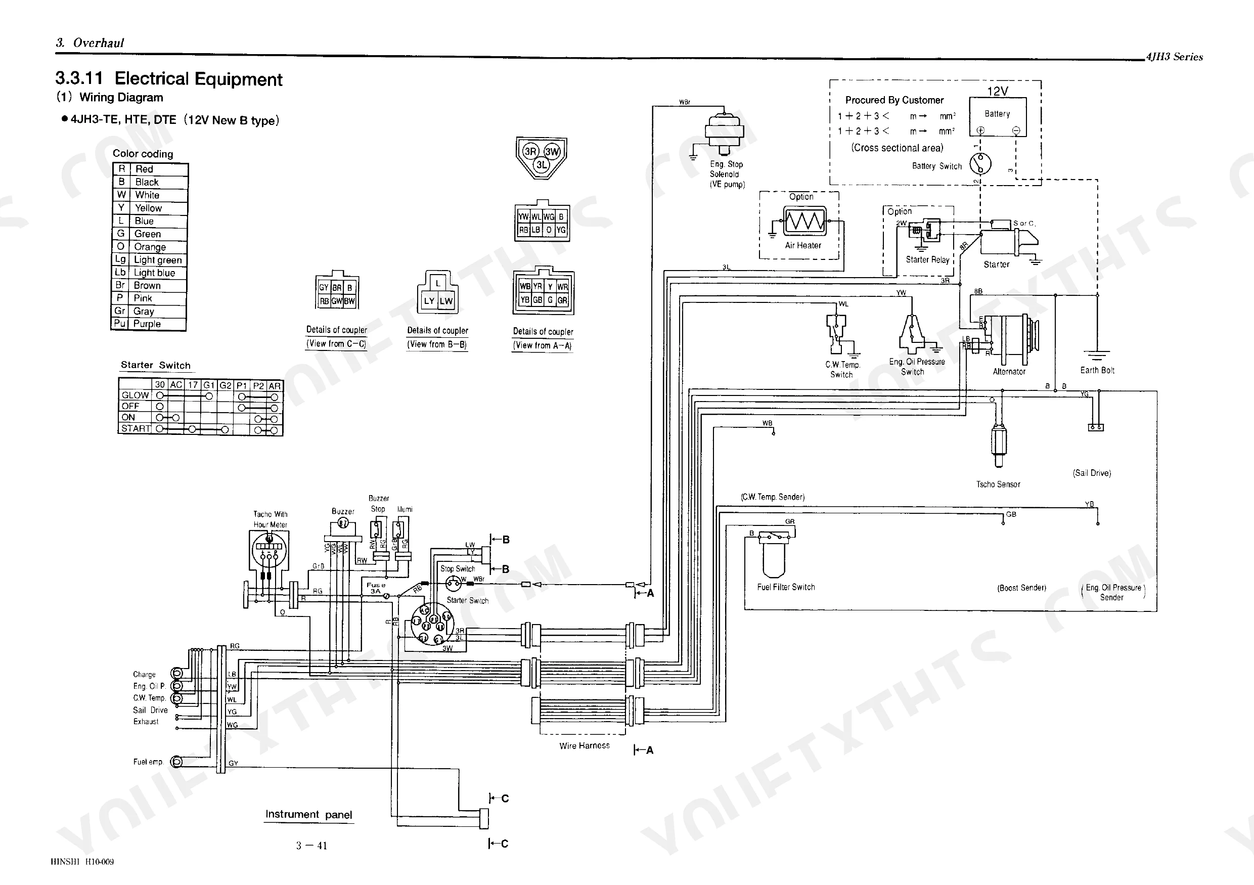
Are electrical wiring diagrams included in this Yanmar 4JH3-TE, 4JH3-HTE?
Yes, full electrical schematics are included with wire colors, connector locations, and circuit descriptions.

Reviews
There are no reviews yet.