


Part of the Yanmar Parts Manuals.
Tracking down the right part for your marine engine just got easier with this 110-page Yanmar 4JH2E parts catalog PDF (OEM #Y00R3512), which covers the complete component breakdown for the 4JH2E, 4JH2-TE, 4JH2-THE, 4JH2-DTE, 4JH2-UTE(B), and 4JH2-HTE series. Inside, you get highly detailed exploded views of every system, from the KM4A clutch assembly to the main fuel injection pump. Open to any page and find exact part numbers, sub-assemblies, and hardware cross-references needed to order the correct replacement components the first time. Factory diagrams show the exact cooling sea water hose dimensions at 13/20x300mm, alongside the precise 20x35x8mm sea water pump seal. Waiting on the wrong replacement part keeps your boat tied to the dock. Grab this bookmarked download, find your exact numbers, and get your engine running today.
What's Inside This Yanmar 4JH2 Parts Manual
| System | Pages | Key Topics |
|---|---|---|
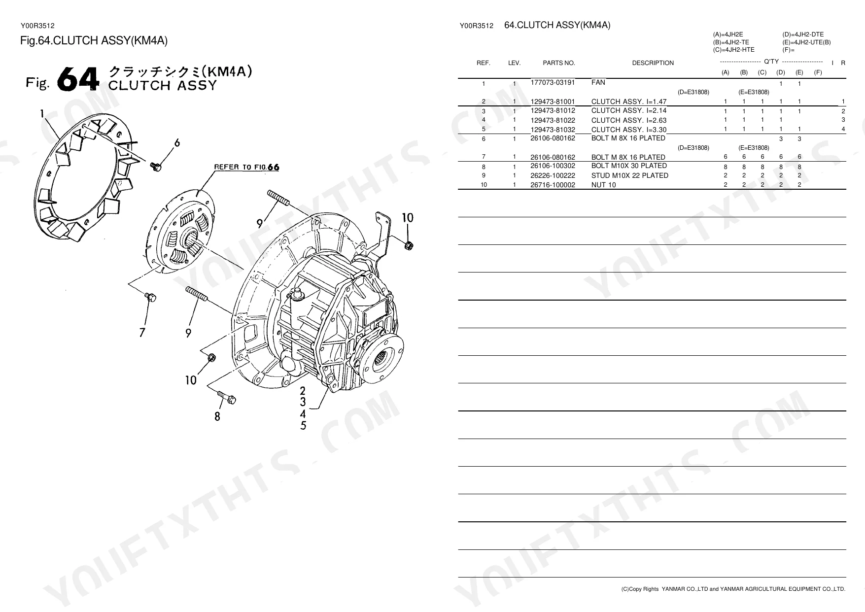
| Clutch & Transmission | Clutch Remote Control, Clutch Assy, Clutch Housing, Clutch Shaft, Counter Shaft, Input Shaft & Counter Shaft | |
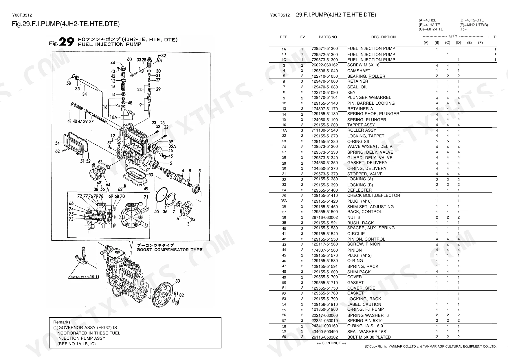
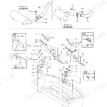
| Fuel System | Fuel Injection Pump, Fuel Injection Pipe, Fuel Pipe, Governor, Engine Stop & Cold Start Device, Fuel Tank, Engine Stop Device | |
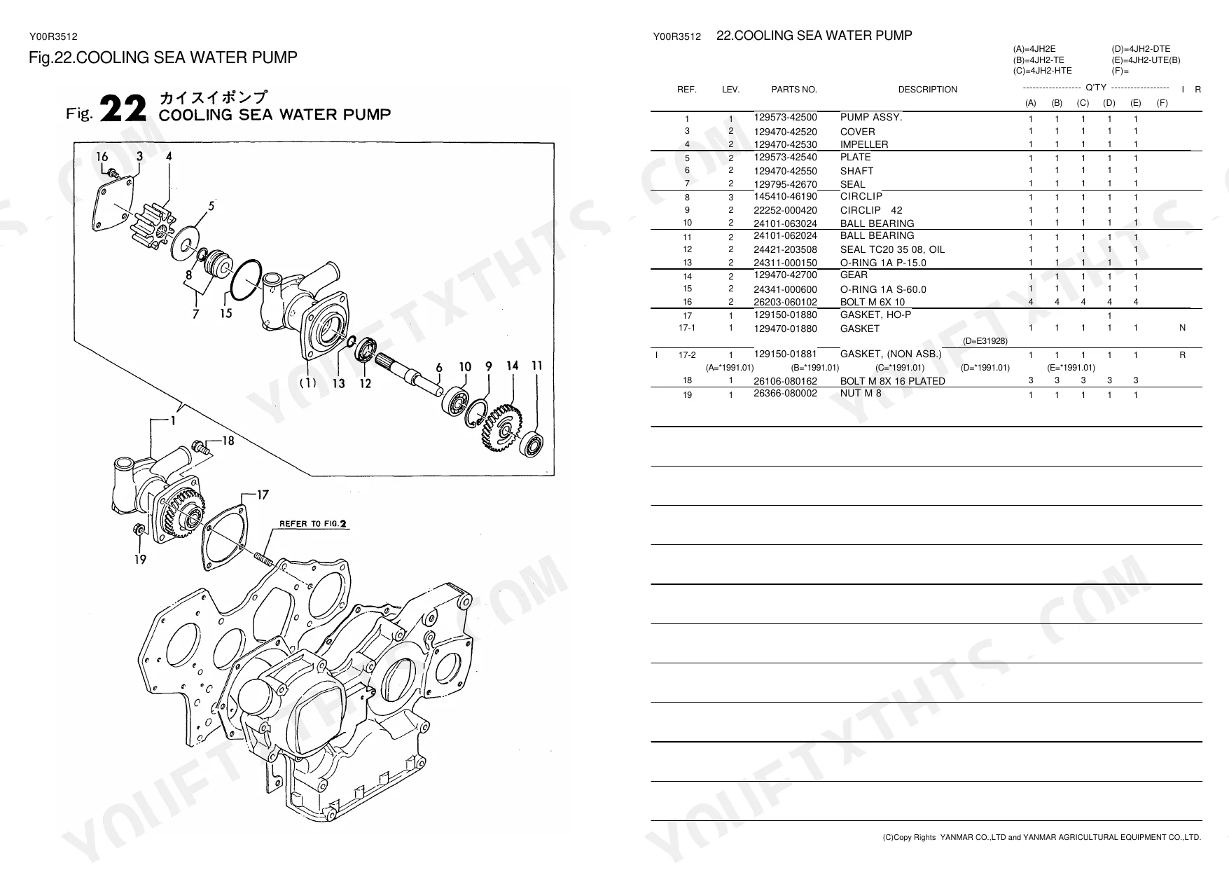
| Cooling System | Air Cooler, Lubrication Oil Cooler, Cooling Sea Water Pump, Cooling Fresh Water Pump, Cooling Fresh Water Cooler, Cooling Sea Water Pipe, Cooling Fresh Water Pipe, Sea Water Filter | |
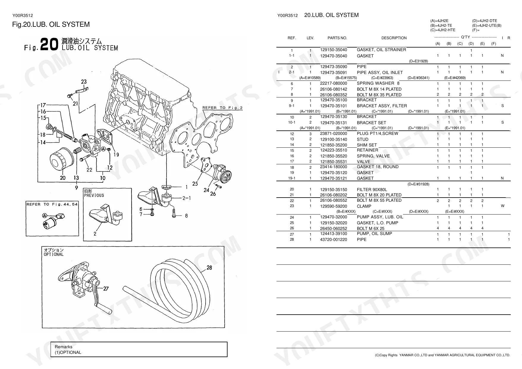
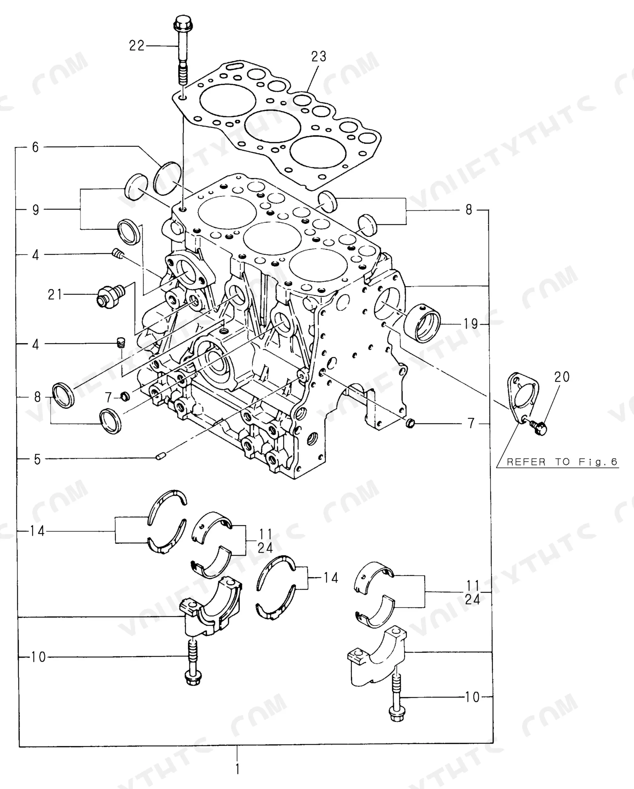
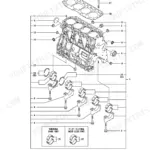
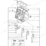
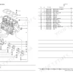
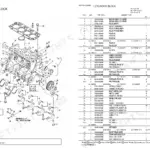
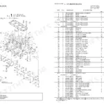
| Engine | Cylinder Block, Flywheel Housing, Lubrication Oil Sump, Cylinder Head, Bonnet & Breather, Camshaft & Driving Gear, Turbocharger, Crankshaft & Flywheel, Piston & Connecting Rod, Lubrication Oil System, Lubrication Oil Line, Gasket Set | |
| Electrical System | Generator, Wire Harness & Sensor, Electric Bilge Pump | |
| Hydraulics & 3-Point Hitch | Speed Remote Control Device | |
| Body & Operator Station | Instrument Panel | |
| Decals & Accessories | Label, Tool | |
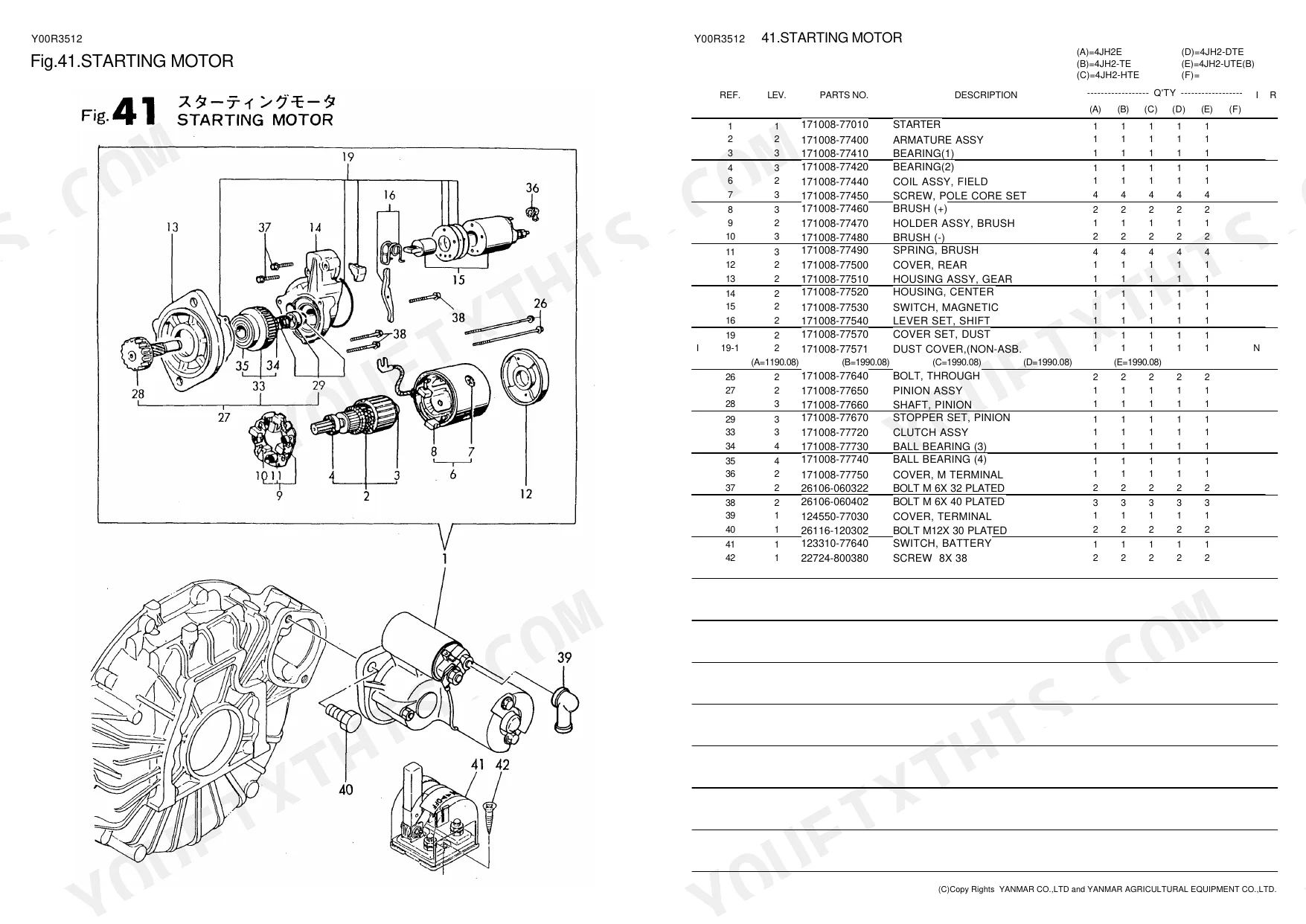
| Other Components | Gear Housing, Mounting Foot, Suction Manifold, Mixing Elbow, Timer, Starting Motor, Spare Part, Coupling, Single Lever Control, Repair Set, Reequip Ment Kit, Input Shaft, Output Shaft, Control Device |
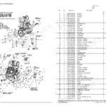
Every system also includes a parts list.
Quick Reference Specifications
| Specification | Value | Page |
|---|---|---|
| Impeller quantity | 1 unit | p. 51 |
| Fuel Strainer Assembly quantity | 1 unit | p. 51 |
| Thermostat quantity | 1 unit | p. 51 |
| Sea Water Pump Seal Dimension | 20x35x8mm | p. 24 |
| Cooling Sea Water Hose (ID/OD x Length) | 13/20x300mm | p. 28 |
| Generator Output | 12V-55A | p. 49 |
| Electric Bilge Pump Voltage | 12V | p. 56 |
| Fuel Tank Capacity | 30L | p. 58 |
| Remote Control Cable Length | 7m | p. 63 |
| Instrument Panel Fuse Rating | 3A | p. 67 |
Yanmar 4JH2 Common Problems This Manual Covers
Cannot locate the correct exhaust mixing elbow part number for Yanmar 4JH2E after discovering cylinder water intrusion
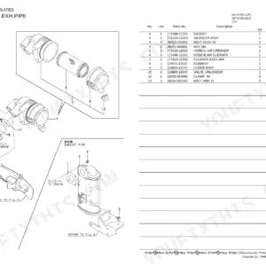
Inspect the exploded view on page 14 to identify the exact mixing elbow assembly. Cross-reference the required gaskets and clamps before ordering. Check the cooling sea water pump breakdown on page 24 and replace the 20x35x8mm oil seal while servicing the raw water system.
Manual Section: Mixing Elbow p. 14Need replacement component part numbers after finding severe carbon buildup and black smoke under heavy load
Review the turbocharger parts breakdown on page 15. Identify the exact turbine housing and gasket part numbers for your specific serial number. Replace the cooling sea water hose with a new 13/20x300mm line listed on page 28 to ensure proper flow to the intercooler system.
Manual Section: Turbocharger p. 15Struggling to identify correct instrument panel replacement components after experiencing a complete loss of gauge readings
Examine the C-Type instrument panel diagram on page 66 to find the correct gauge part numbers. Verify the wiring harness connectors match your existing setup. Order a replacement 3A fuse as specified on page 67 to resolve the circuit failure.
Manual Section: Instrument Panel (C-Type) p. 66Unable to find fuel pickup tube and strainer part numbers during a troubleshooting procedure for low RPM
Check the fuel tank diagram on page 58 to locate the correct pickup tube and strainer assemblies for your 30L capacity tank. Match the replacement component numbers to your specific configuration. Review page 40 to identify matching fuel pipe routing clips.
Manual Section: Fuel Tank p. 58Frequently Asked Questions
What are the replacement specifications for Exhaust elbow / mixing elbow?
The replacement specifications for the mixing elbow include "ELBOW, MIXING" (Part No. 129792-13552) for 4JH2E, 4JH2-TE, 4JH2-HTE, and 4JH2-DTE engines, and "ELBOW,WATER MIXING" (Part No. 129470-13560) for 4JH2E. Associated gaskets are "GASKET" (Part No. 129472-13520) for 4JH2E, 4JH2-TE, 4JH2-HTE, and 4JH2-DTE, and "GASKET" (Part No. 129472-18090) for 4JH2E. p. 14
What are the replacement specifications for Service kit / filters / impeller kit?
Replacement specifications include various repair sets, filters, and impellers. For general repair, "REPAIR SET" part numbers vary by engine model, such as 729570-92500 for 4JH2E and 729571-92500 for 4JH2-TE. For lubrication oil, "FILTER 90X80L" (Part No. 129150-35150) is used across all models. Sea water filtration uses "STRAINER" (Part No. 919400-02500) and "FILTER" (Part No. XTST25S009). For cooling sea water pump, the "IMPELLER" is Part No. 129470-42530, and for the electric bilge pump, it is Part No. 947859-20010. p. 78
How do you fix cannot locate the correct exhaust mixing elbow part number for Yanmar 4JH2E after discovering cylinder water intrusion?
Inspect the exploded view on page 14 to identify the exact mixing elbow assembly. Cross-reference the required gaskets and clamps before ordering. Check the cooling sea water pump breakdown on page 24 and replace the 20x35x8mm oil seal while servicing the raw water system. p. 14
How do you fix need replacement component part numbers after finding severe carbon buildup and black smoke under heavy load?
Review the turbocharger parts breakdown on page 15. Identify the exact turbine housing and gasket part numbers for your specific serial number. Replace the cooling sea water hose with a new 13/20x300mm line listed on page 28 to ensure proper flow to the intercooler system. p. 15
How will I receive this Yanmar 4JH2E & variants Parts Catalog?
This is a 110-page searchable PDF ready for immediate download. Works on any device, so pull it up on your phone while you're under the hood. No shipping, no waiting.
Can I print specific sections of this Yanmar 4JH2E & variants Parts Catalog?
No restrictions at all. Print individual pages, full chapters, or the entire manual. The PDF is completely unlocked.
Reviews
There are no reviews yet.