


Part of the Yanmar Parts Manuals.
Need the exact factory breakdown for your marine engine? All 101 pages of this Yanmar 4LH-UT, 4LH-ST, 0CF10-G29805 Parts Catalog PDF (OEM #0CF10-G29805) focus on delivering precise component data for your entire 4LH-UT and 4LH-ST engine family. Open to high-resolution exploded views covering the cylinder block, gear housing, fuel injection pump, and sea water cooling systems. You get every original part number, detailed hardware descriptions, and exploded parts diagrams for wire harness assemblies with part numbers. Verify your hardware matches the factory standard, like the 8x16 mm parallel pins in the cylinder block or the exact M6x18 mm bolts used in the gear housing. Ordering the wrong component burns daylight. Download this bookmarked file right to your tablet, find the exact part number, and get your engine running.
What's Inside This Yanmar 4LH Parts Manual
| System | Pages | Key Topics |
|---|---|---|
| Clutch & Transmission | Clutch, Fpto Electton Clutch | |
| Fuel System | Fuel Injection Pump, Governor, Fuel Feed Pump, Fuel Pipe, Engine Stop Device | |
| Cooling System | Suction Manifold & Air Cooler, Lub.Oil Cooler, Cooling Fresh Water Pump, Cooling Sea Water Pump, C.F.W.Cooler & Cover, Cooling Sea Water Pipe, Cooling Fresh Water Pipe | |
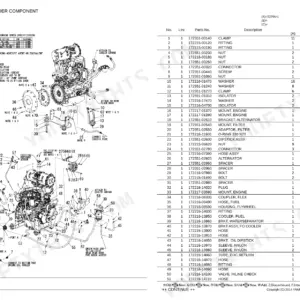
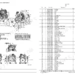
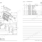
| Engine | Cylinder Block, Breather, Engine Bracket, Cylinder Head & Bonnet, Turbocharger & Mixing Elbow, Turbocharger Component Part, Camshaft & Crankshaft, Piston & Connecting Rod | |
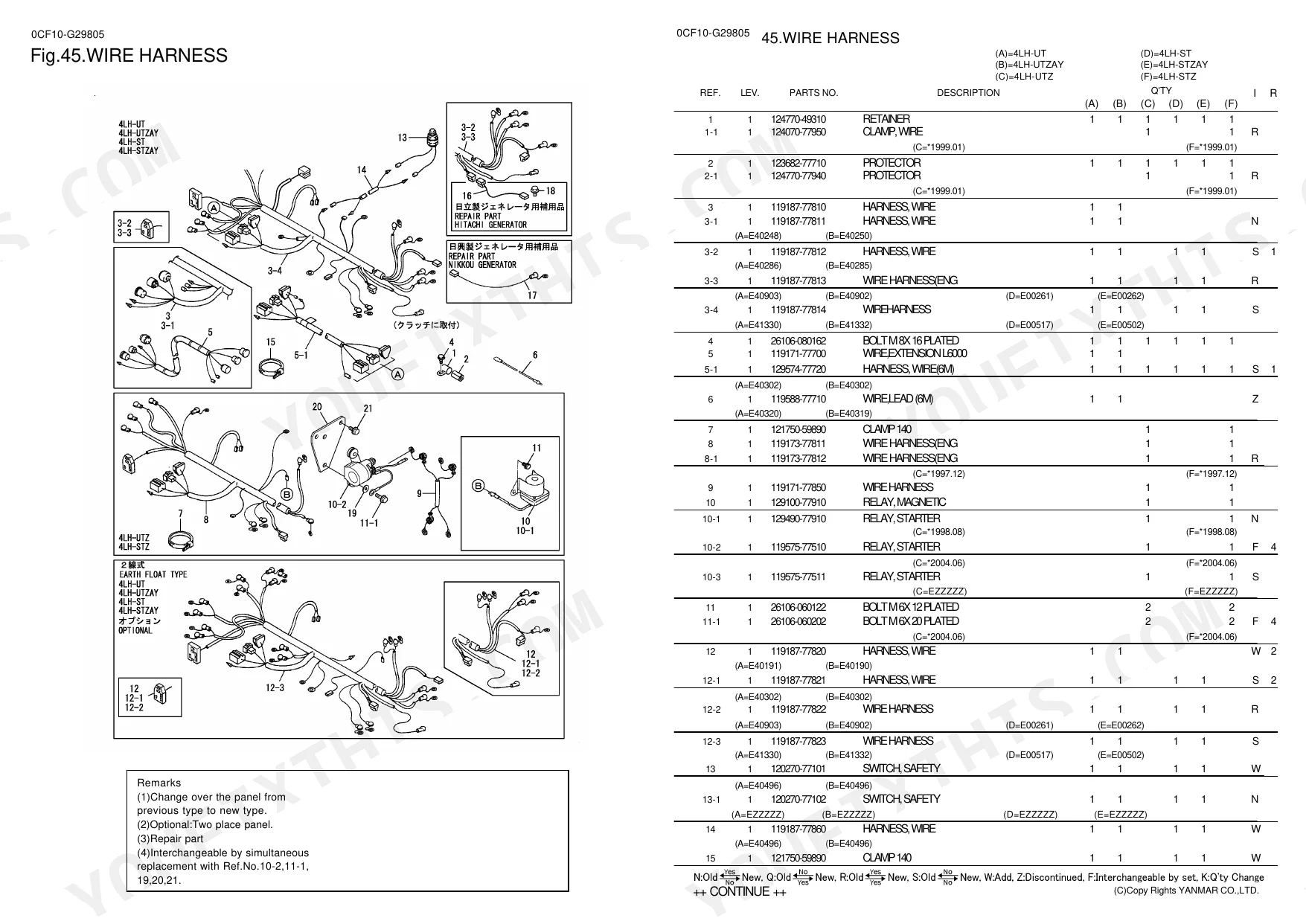
| Electrical System | Generator, Wire Harness, Sensor | |
| Hydraulics & 3-Point Hitch | Timer & F.I.Pump Mount, F.I.Valve & F.I.Pipe, Bilge Pump | |
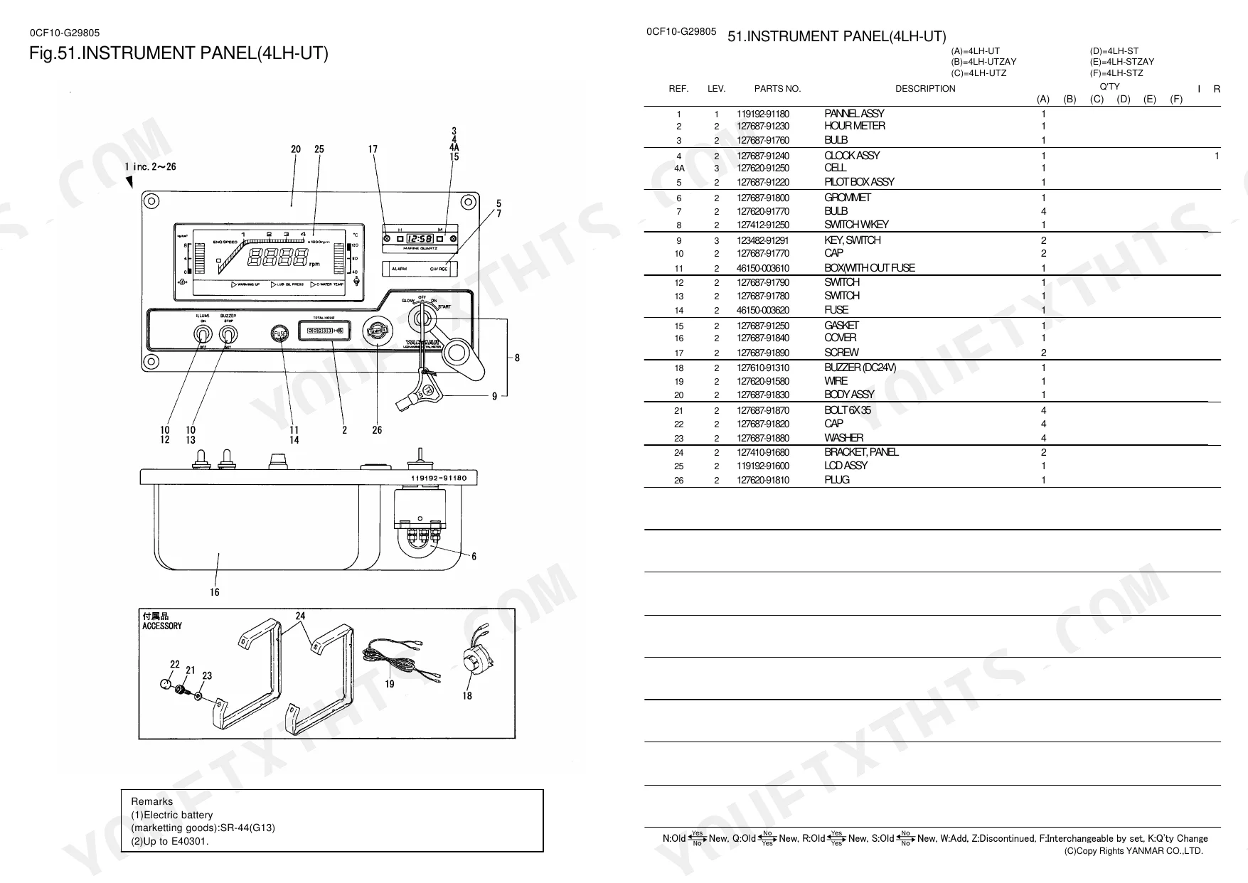
| Body & Operator Station | Front Bracket, Air Duct, Instrument Panel | |
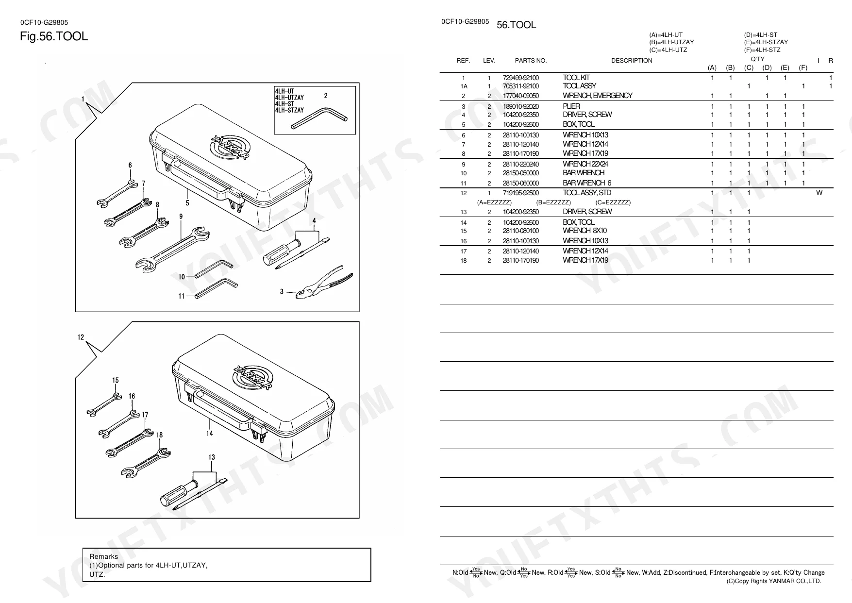
| Decals & Accessories | Label, Tool, Safety Label | |
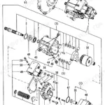
| Other Components | Gear Housing, L.O.Sump & Oil Seal Housing, Balancer, Lub.Oil System, Starting Motor, Front Driving Device |
Every system also includes a parts list.
Quick Reference Specifications
| Specification | Value | Page |
|---|---|---|
| Parallel Pin Dimension | 8x16 mm | p. 1 |
| Bolt Dimension | M6x18 mm | p. 3 |
| Pipe Dimension | 7x300 mm | p. 7 |
Yanmar 4LH Common Problems This Manual Covers
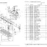
Yanmar 4LH-UT cylinder head and bonnet part numbers needed for gradual compression loss and rough running
Inspect the cylinder head and bonnet exploded view on page 13 to identify replacement components. Locate the exact M8x45 mm bolts required for the assembly. Match these hardware part numbers against your specific engine serial number before ordering to guarantee a proper fit during your top-end rebuild.
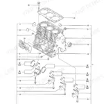
Manual Section: Cylinder Head & Bonnet p. 13Breather component and hose part numbers needed due to excessive crankcase pressure and oil misting
Review the breather parts diagram on page 7 to find the correct replacement components. Identify the 7x300 mm pipe required for the routing system. Check the interchangeable parts list to verify if your specific engine configuration uses the standard or optional breather hose assembly before placing your parts order.
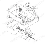
Manual Section: Breather p. 7Gear housing cover hardware and gasket part numbers required to fix sudden front engine oil leaks
Check the gear housing exploded view on page 3 for the complete parts list. Locate the specific M6x18 mm bolts needed to secure the housing cover. Verify the correct part numbers for all associated gaskets and seals to ensure you order everything required to fix the front-end oil leak.
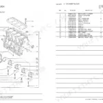
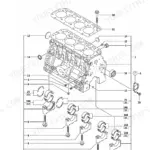
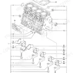
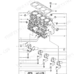
Manual Section: Gear Housing p. 3Cylinder block alignment pin replacement part numbers needed following major internal damage and sudden overheating
Examine the cylinder block parts diagram on page 1. Find the required 8x16 mm parallel pins needed for proper block alignment. Cross-reference the exact pin part numbers with the master index to ensure you receive the correct hardware for your engine block replacement or complete machine overhaul.
Manual Section: Cylinder Block p. 1Frequently Asked Questions
How do you fix yanmar 4LH-UT cylinder head and bonnet part numbers needed for gradual compression loss and rough running?
Inspect the cylinder head and bonnet exploded view on page 13 to identify replacement components. Locate the exact M8x45 mm bolts required for the assembly. Match these hardware part numbers against your specific engine serial number before ordering to guarantee a proper fit during your top-end rebuild. p. 13
How do you fix breather component and hose part numbers needed due to excessive crankcase pressure and oil misting?
Review the breather parts diagram on page 7 to find the correct replacement components. Identify the 7x300 mm pipe required for the routing system. Check the interchangeable parts list to verify if your specific engine configuration uses the standard or optional breather hose assembly before placing your parts order. p. 7
How do you fix gear housing cover hardware and gasket part numbers required to fix sudden front engine oil leaks?
Check the gear housing exploded view on page 3 for the complete parts list. Locate the specific M6x18 mm bolts needed to secure the housing cover. Verify the correct part numbers for all associated gaskets and seals to ensure you order everything required to fix the front-end oil leak. p. 3
How do you fix cylinder block alignment pin replacement part numbers needed following major internal damage and sudden overheating?
Examine the cylinder block parts diagram on page 1. Find the required 8x16 mm parallel pins needed for proper block alignment. Cross-reference the exact pin part numbers with the master index to ensure you receive the correct hardware for your engine block replacement or complete machine overhaul. p. 1
What do I get after purchasing this Yanmar 4LH-UT & variants manual?
Instant PDF download. You get the full 101-page searchable Parts Catalog immediately after payment. Open it on your laptop, tablet, or phone right in the shop.
Can I print specific sections of this Yanmar 4LH-UT & variants Parts Catalog?
Yes, print as many copies as you want, and there are no restrictions. Many mechanics print the section they need and bring it to the shop floor.
Are electrical wiring diagrams included in this Yanmar 4LH-UT & variants manual?
No. This is a parts catalog — it includes exploded parts diagrams and wire harness assembly drawings with part numbers, but does not contain full electrical circuit diagrams.

Reviews
There are no reviews yet.