


Part of the Yanmar Parts Manuals.
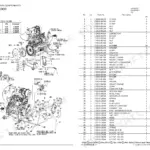
All 51 pages of this 4TNV98T-ZSTBW, P-T175WECF Parts Catalog are built for one job: finding the right part number before you call the counter. Inside, exploded-view assemblies walk you through every system on this turbocharged diesel, including the cylinder block, gear housing, flywheel housing and oil sump, cylinder head and bonnet, suction manifold and air cleaner, exhaust manifold and silencer, camshaft and driving gear, turbine, crankshaft and piston, hydraulic pump, lube oil system, lube oil line, cooling water system, fuel injection pump, governor, fuel injection valve, fuel line, starting motor, generator, electric parts, and a complete gasket set. Each figure pairs a labeled exploded diagram with its numbered parts list for fast component identification. Cross-reference your 12V/3KW starting motor assembly or confirm the V-Belt (B45) straight from the factory drawing. Stop guessing at part numbers. Bookmark your assembly, grab the OEM number, place the order.
What's Inside This Yanmar 4TNV98T-ZSTBW, P-T175WECF Parts Manual
| System | Pages | Key Topics |
|---|---|---|
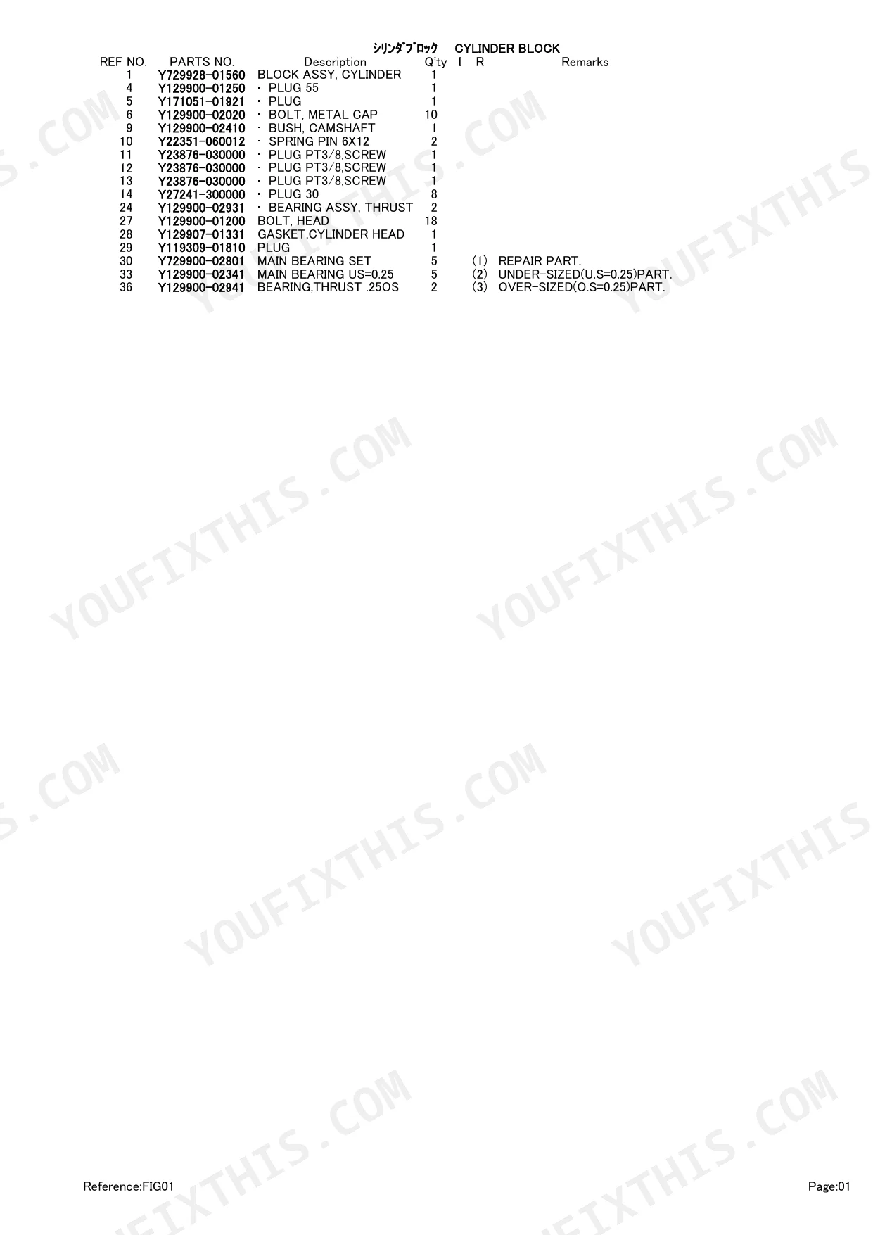
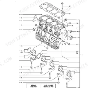
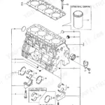
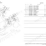
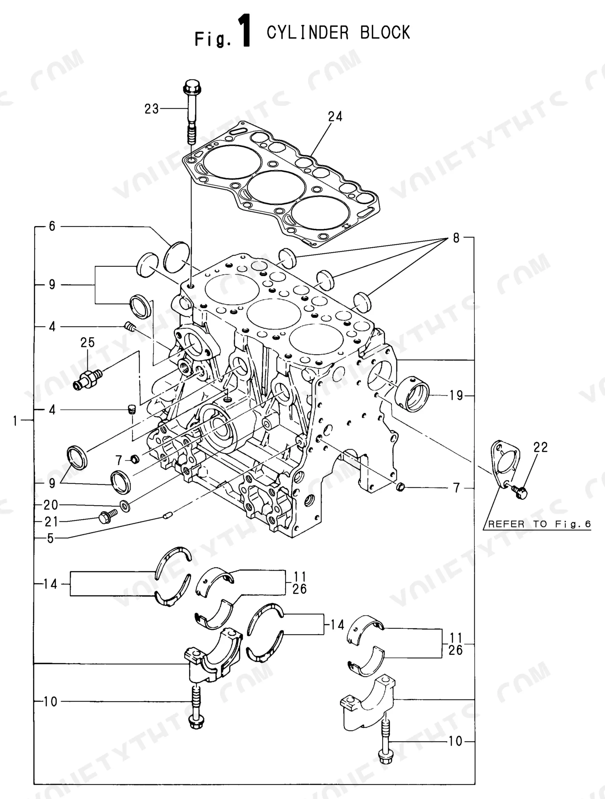
| Cylinder Block | 6-7 | Cylinder Block Assy, Camshaft Bush, Thrust Bearing Assy, Cylinder Head Gasket, Main Bearing Set Repair Part, Main Bearing Under-Sized Part, Thrust . Over-Sized Part Bearing |
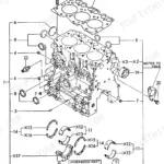
| Gear Housing | 8-9 | Gears Housing, Lub. Oil Pump Assy, Packing, Filler Cover, Fuel Injection Pump Cover, Fuel Injection Pump S Cover, Cover, G Housing Assy, Oil Seal |
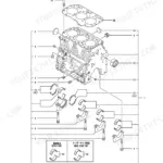
| Flywheel Housing & Oil Sump | 10-11 | Flywheel Housing, Oil Seal, Lub. Oil Sump Assy, Pin |
| Cylinder Head & Bonnet | 12-13 | Engine Lifter, Valve Bridge Seat a, Cylinder Head Assy, Valve, Valve Spring, Spring Retainer, Valve Stem Seal, Valve Bridge Assy |
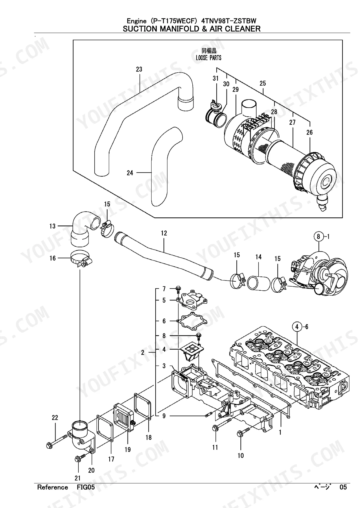
| Suction Manifold & Air Cleaner | 14-15 | Packing, Intake Manifold Cmp, Intake Manifold, Reedvalve, Spacer Valve, Gasket Spacer, Suction Duct, Rubber Joint |
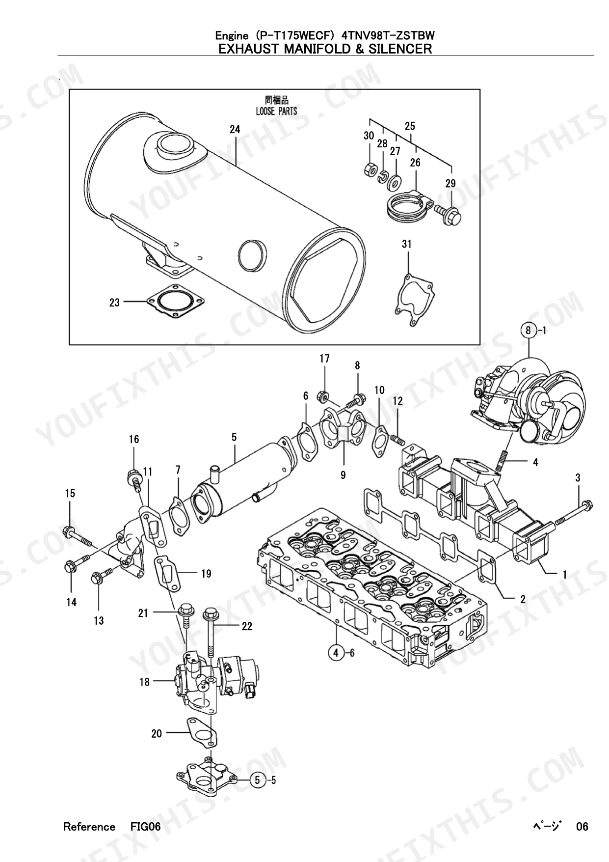
| Exhaust Manifold & Silencer | 16-17 | Exhaust Manifold, Gasket, EGR Cooler, EGR Cooler Gasket, Pipe in, EGR Pipe Gasket, Pipe Out, EGR Valve |
| Camshaft & Driving Gear | 18-19 | Tappet, Push Rod, Camshft Assy, Thrust Metal, Camshaft Gear, Shaft, Idle Gear Assy, Idle Gear Repair Part Bush |
| Turbine | 20-21 | RHF5 Turbine, Turbine S, Gasket, Nut |
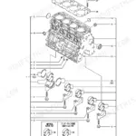
| Crankshaft & Piston | 22-23 | Crankshaft Comp, Crankshaft Gear, Crankshaft V-Pulley, Flywheel Assy, Ring Gear, Piston Assy, Piston Ring Set, Connecting Rod Assy |
| Hydraulic Pump | 24-25 | Gear, Gasket, Hydraulic Oil Pump Assy, Square Ring, Oil Seal TC15 |
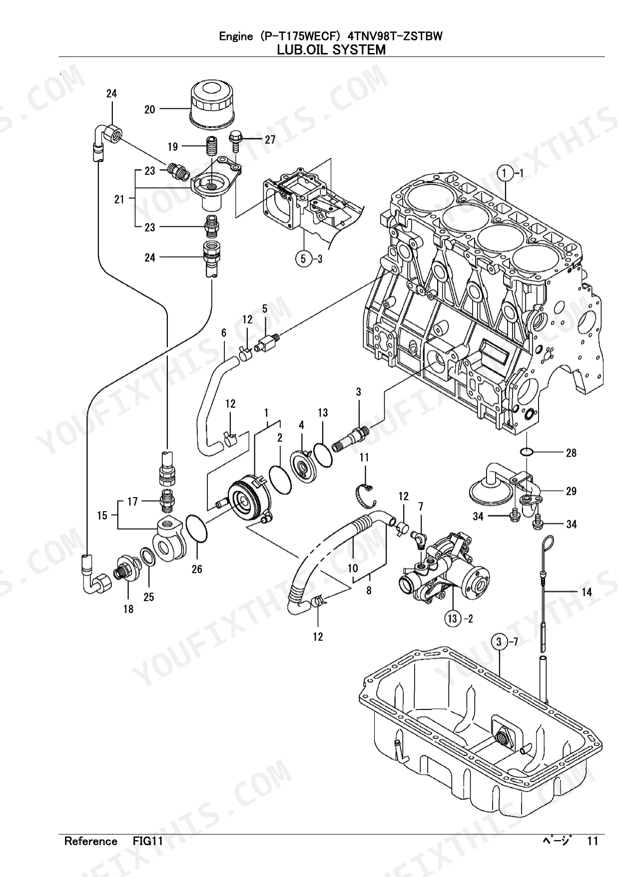
| Lub.Oil System | 26-27 | Oil Cooler Assy, Oil Cooler Bracket, Joint, Cooling Water Pipe, Elbow PT3, Cw-T Protecter, Lub. Oil Dipstic, Case |
| Lub.Oil Line | 28-29 | Lub. Oil Pipe Assy, Retainer, Joint Bolt Assy, Round Gasket, Lub. Oil Switch, Pipe Support, Pipe, Elbow |
| Cooling Water System | 30-31 | Cw-P Gasket, Water Pump Assy, V-Pulley, V-Belt B45, V-Belt B44. N, Cooling Fan, Fan Spacer, Thermostat Case Assy |
| Fuel Injection Pump | 32-33 | Injecton Pump Assy, Stopper, Dilevery Valve Assy, Spring, Delivery Holder, Lifter, Timer Set, Timer Cmp |
| Governor | 34-35 | Case Packing, Governor Case Assy, Link, Governor Lever Shaft, Governor Lever Spacer, Governor Lever, Spring, Spring Fuck |
| Fuel Injection Valve | 36-37 | Fuel Injector, Nozzle Assy, Nozzle Holder Assy, Nozzle Spring, Nozzle Spring Seat, Stop Plate, Pipe Seal, Bracket |
| Fuel Line | 38-39 | F.o.return Pipe Assy, Fuel Return Packing, Fuel Return Pipe, Corrugated Tube, Hose Joint, Fuel Pump, Fuel Filter Assy, Fuel Filter Bracket |
| Starting Motor | 40-41 | 3KW Starter 12V, Armature Assy, Field Coil Assy, Brush, Rear Cover, Brush Holder, Brush Spring, Magnetic Switch Assy |
| Generator | 42-43 | Rotator Assy, Bearing Cover, Frame Assy, Plate, Flame, Collar, Regulator Assy |
| Electric Parts | 44-45 | ECU Cmp, ECU Cmp S, ECU Shield, Controller Collar, Cushion Rubber, Type C Relay Ca, Controller, Relay |
Quick Reference Specifications
| Specification | Value | Page |
|---|---|---|
| Oil Pressure Switch Activation | 0.5 kg | p. 29 |
| Starter Motor Voltage | 12V | p. 41 |
| Starter Motor Power | 3KW | p. 41 |
| Relay Current Rating (ISO.70A) | 70A | p. 45 |
| V-Belt Size (B45) | B45 | p. 31 |
| V-Belt Size (B44.5) | B44.5 | p. 31 |
Yanmar 4TNV98T-ZSTBW, P-T175WECF Common Problems This Manual Covers
Oil pressure switch and lube line part numbers unclear after oil pressure warning light comes on
Check the Lub.Oil Line exploded view on page 28. The oil pressure switch, check valve assembly, pipe joints, and seal washers are listed by part number on page 29. The switch activates at 0.5 kg, so also cross-reference the Lub.Oil System on page 26 to identify oil cooler assembly and bracket part numbers if restriction or contamination is suspected.
Manual Section: Lub.Oil Line p. 28Turbocharger gasket and mounting hardware part numbers missing, engine losing power or producing smoke
Check the Turbine section on page 20. The RHF5 turbocharger gasket and mounting nuts are individually listed by part number in that diagram. For intake-side components including the EGR valve, EGR cooler pipes, and suction manifold reed valve, check page 14. Exhaust manifold gaskets and remaining EGR-related components are listed on page 16.
Manual Section: Turbine p. 20Frequently Asked Questions
How do you fix 4TNV98T-ZSTBW fuel filter assembly and injection pump part numbers needed after no-start condition?
Check the Fuel Line exploded view on page 38. The fuel filter assembly, body, and fuel sensor components are identified by part number in that diagram. For injection pump, delivery valve holders, and timer set part numbers, cross-reference the Fuel Injection Pump section starting on page 32. Confirm serial number applicability before ordering any fuel-system component. p. 38
How do you fix water pump, thermostat, and drive belt part numbers needed for cooling system overhaul, engine overheating?
Check the Cooling Water System exploded view on page 30. Water pump assembly, V-pulley, cooling fan, and thermostat part numbers are all listed in that diagram. The replacement v-belt is size B45 (or B44.5 depending on configuration), confirmed on page 31. Order all pipe assemblies and hose fittings from the same section by part number. p. 30
How do you fix cylinder head gasket set part number needed for rebuild after overheating and coolant contamination?
Check the Gasket Set section starting on page 46. The index on page 48 lists individual gasket and seal part numbers, including the cylinder head gasket, O-rings, valve stem seals, and intake manifold packing. Confirm whether the full NON-ASB. gasket set covers your repair scope, or identify individual components by part number for a partial order. p. 46
How do you fix starter motor subassembly part numbers needed, engine cranks slowly or starter fails to engage?
Check the Starting Motor exploded view on page 40. The armature assembly, field coil, brush set, magnetic switch assembly, pinion assembly, and clutch assembly are each listed by individual part number in that diagram. This starter is rated 12V, 3KW (page 41). Verify voltage compatibility before ordering any subassembly or a complete starter unit. p. 40
What do I get after purchasing this Yanmar 4TNV98T-ZSTBW manual?
This is a 51-page searchable PDF ready for immediate download. Works on any device, so pull it up on your phone while you are under the hood. No shipping, no waiting.
Am I free to print this Yanmar 4TNV98T-ZSTBW Parts Catalog?
There are no print restrictions — the PDF is DRM-free. Print whatever sections you need to take out to the shop. Standard letter or A4 paper works.
Reviews
There are no reviews yet.