


Part of the Yanmar Parts Manuals.
Hunting for the correct replacement numbers for your rubber crawler carrier? This 126-page Yanmar C50R-3B Parts Catalog PDF (OEM #0CS10-M56000EN) breaks down every single assembly from the undercarriage to the dump vessel. You get highly detailed exploded diagrams showing exactly how the travel motors, hydraulic pumps, and turning frames fit together on the factory floor. Open up the chassis or drivetrain sections to find complete component lists alongside clear illustrations, making your parts ordering completely foolproof. Verify that the lower truck roller requires a P1.5 thread pitch bolt, or confirm you are installing the correct 45A main fuse for the wire harness. Stop wasting money on incorrect parts from vague aftermarket websites. Download this bookmarked file right to your phone, locate your exact hardware instantly, and get your machine back in the dirt.
What's Inside This Yanmar C50R-3B Parts Manual
| System | Pages | Key Topics |
|---|---|---|
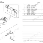
| Fuel System | Fuel Oil Tank | |
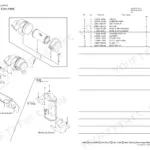
| Cooling System | Cooler, Cooler Bracket | |
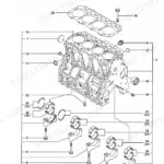
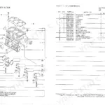
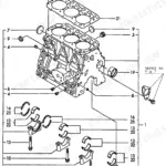
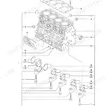
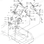
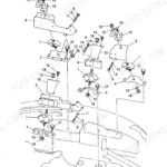
| Engine | Turning Bearing, Engine & Related Device, Engine Control, Hyd. Oil Pump | |
| Electrical System | Electric Part, Battery, Vessel Center Lamp, Head Light, Back Light, Turn Signal Lamp, Solenoid Valve | |
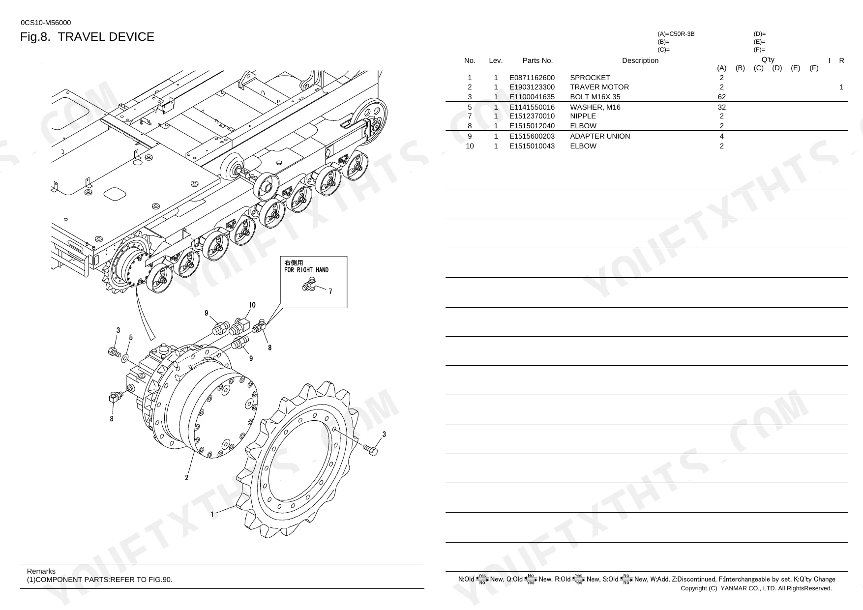
| Undercarriage & Travel | Crawler Belt, Carrier Roller, Truck Roller, Idler, Travel Device, Travel Lever, Travel Lever Piping, Travel Motor | |
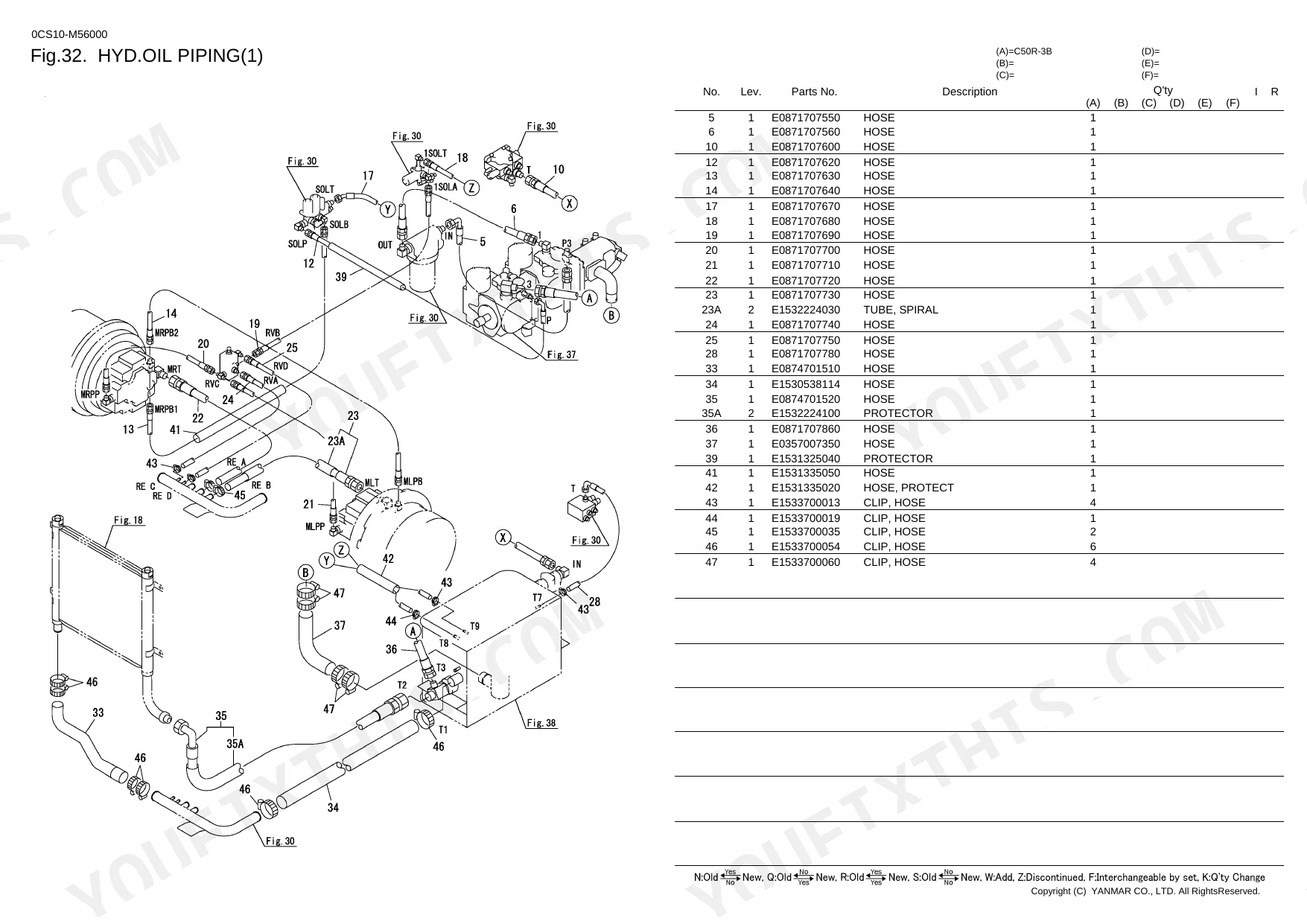
| Hydraulics & 3-Point Hitch | Swivel Joint, Grease Piping, Valve, Hyd.Oil Piping, Turning Dump Piping, Pump Driving, Hyd. Oil Tank, Control Valve, Remote Control Valve, Auto Tension Valve, Depression Valve, Dump Cylinder, Truck Shoe Cylinder, Turning Motor, Gear Pump | |
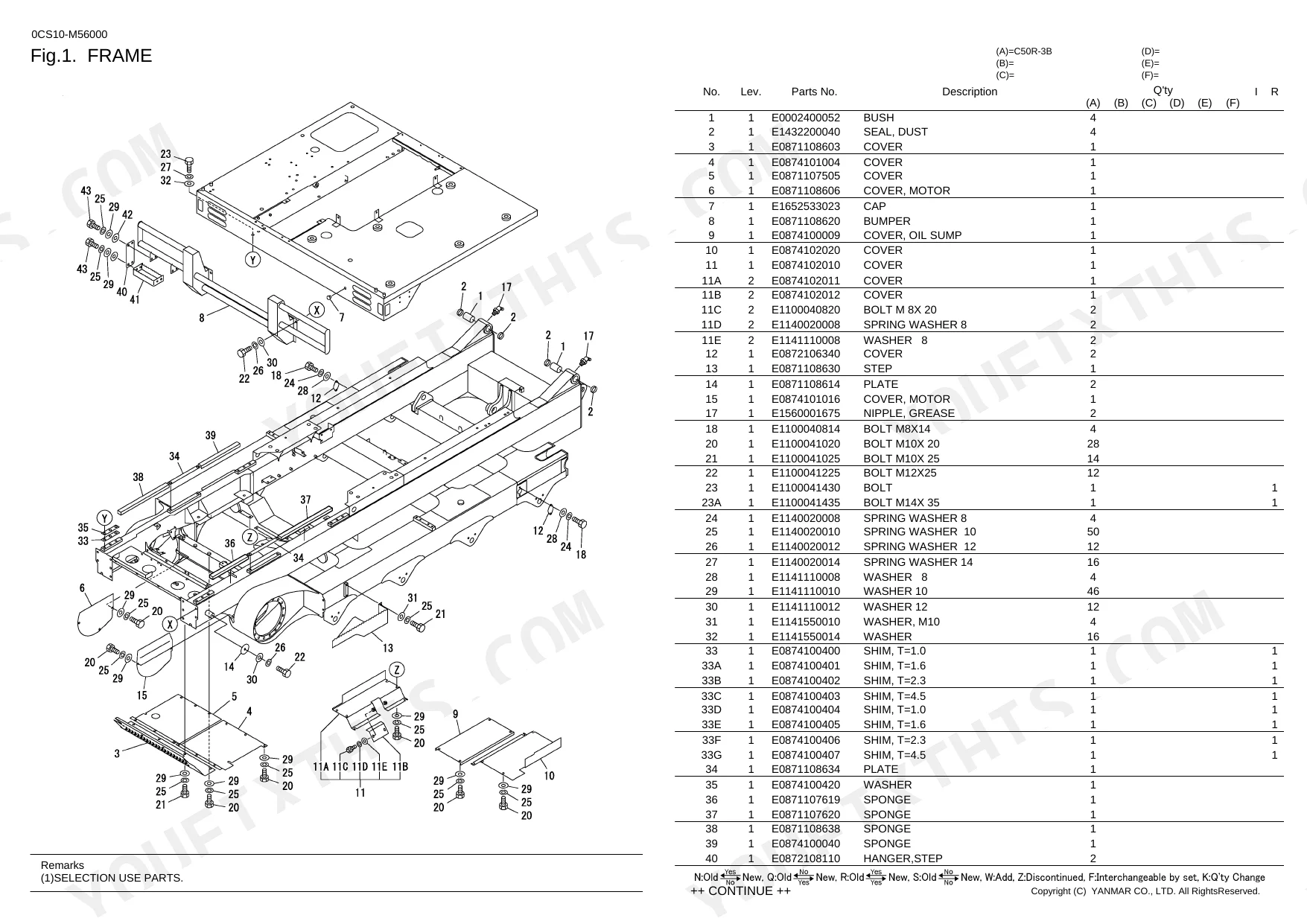
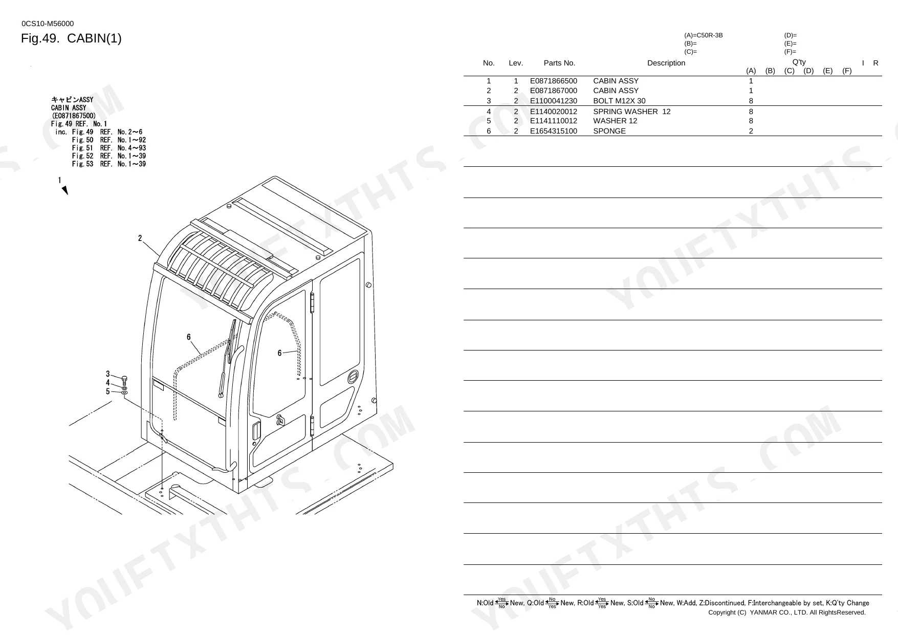
| Body & Operator Station | Frame, Turning Frame, Wind Washer, Back Mirror, Floor, Seat, Cabin, Canopy, Heater, Radio | |
| Decals & Accessories | Label, Tool | |
| Other Components | Truck Adgusta, Turning Device, Dump & Turning Lever, Control Box, Back Buzzer, Balustrade, Defroster, Vessell, Dump Body, Rear Link, Open and Close Lever, Painted Color, Block, Swivel Selector |
Quick Reference Specifications
| Specification | Value | Page |
|---|---|---|
| Fuse Rating | 45A | p. 32 |
| Handrail Length | 440mm | p. 59 |
| U-Bolt Assembly Size | 32A | p. 83 |
| Bolt Thread Pitch | P1.5 | p. 14 |
| Pin Spring Dimension | 8X 36 | p. 22 |
Yanmar C50R-3B Common Problems This Manual Covers
Need replacement 450x110x74 rubber tracks for Yanmar C50R-3B after severe wear in abrasive ground conditions
Check the Crawler Belt diagram on page 12 to identify the exact replacement part number. Locate the assembly for the standard 450x110x74 rubber tracks. Verify the track link count matches your machine setup, and cross-reference the part number with your serial range before ordering.
Manual Section: Crawler Belt p. 12Main electrical system dead and need to identify the correct replacement main harness fuses
Inspect the Electric Part exploded view on page 32 to find the main wiring harness layout. Identify the correct part numbers for the 45A and 75A main fuses. Match the fuse block diagram to your machine to order the exact OEM replacement components.
Manual Section: Electric Part p. 32Loose or missing truck roller mounting hardware accompanied by severe undercarriage vibration and noise
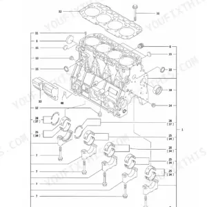
Review the Truck Roller components list on page 14. Find the specific part numbers for the mounting bolts and verify the P1.5 bolt thread pitch. Order the matching washers, seals, and floating O-rings shown in the diagram to complete the roller assembly replacement.
Manual Section: Truck Roller p. 14Broken dump body hardware making the rear link assembly rattle heavily during material transport
Examine the Dump Body parts diagram on page 83. Locate the correct part number for the 32A U-Bolt Assembly Size. Check the adjacent exploded view to find replacement nuts, brackets, and related mounting hardware needed to secure the dump body properly.
Manual Section: Dump Body p. 83Frequently Asked Questions
How do you fix need replacement 450x110x74 rubber tracks after severe wear in abrasive ground conditions?
Check the Crawler Belt diagram on page 12 to identify the exact replacement part number. Locate the assembly for the standard 450x110x74 rubber tracks. Verify the track link count matches your machine setup, and cross-reference the part number with your serial range before ordering. p. 12
How do you fix main electrical system dead and need to identify the correct replacement main harness fuses?
Inspect the Electric Part exploded view on page 32 to find the main wiring harness layout. Identify the correct part numbers for the 45A and 75A main fuses. Match the fuse block diagram to your machine to order the exact OEM replacement components. p. 32
What do I get after purchasing this Yanmar C50R-3B manual?
Instant PDF download (4 MB). You get the full 126-page searchable Parts Catalog immediately after payment. Open it on your laptop, tablet, or phone right in the shop.
Can I print specific sections of this Yanmar C50R-3B Parts Catalog?
Absolutely. No DRM or copy protection. Print the whole manual or just the pages you need. Any home or office printer works.
Reviews
There are no reviews yet.