


Part of the Yanmar Parts Manuals.
Looking for the exact factory part numbers to overhaul your skid-steer loader? This 122-page Yanmar S270V parts catalog PDF (OEM #0CS10-M56800EN) breaks down every single component from the lift cylinders to the hydrostatic drive motors. You get highly detailed exploded views of the entire machine, showing exactly how the chassis, tandem pump, and ROPS structures fit together. Inside, you will find complete parts lists, component identification diagrams, and cross-references to make ordering replacements completely foolproof. Verify your air filter requires part number 172551-02050, and confirm you need fuel filter 129907-55801 before calling the dealership counter. Stop relying on confusing aftermarket diagrams that cost you time. Bookmarked by assembly and ready for any device, just download the file, pull it up in the parts room, and order exactly what your loader needs to run.
What's Inside This Yanmar S270V Parts Manual
| System | Pages | Key Topics |
|---|---|---|
| Clutch & Transmission | Hydrostatic System - Wheel Drives | |
| Fuel System | Air Cleaner and Exhaust | |
| Cooling System | Radiator/Cooler | |
| Engine | Grille and Engine Cover, Controls - Engine, Electrical - Engine | |
| Electrical System | Electrical - Chassis, Electrical - ROPS/Fops, Electrical - ROPS/FOPS, Electrical - Lights, Solenoid Valves - Brake, Joystick Supply and Brake Release, Joystick Supply and Brake Release Brake Release Sole, Backup Alarm Kit, Pin Electrical Auxiliary Connector Kit, Warning Lamp Kit | |
| Rear Axle, Differential & Brakes | Parking Brake Release Kit | |
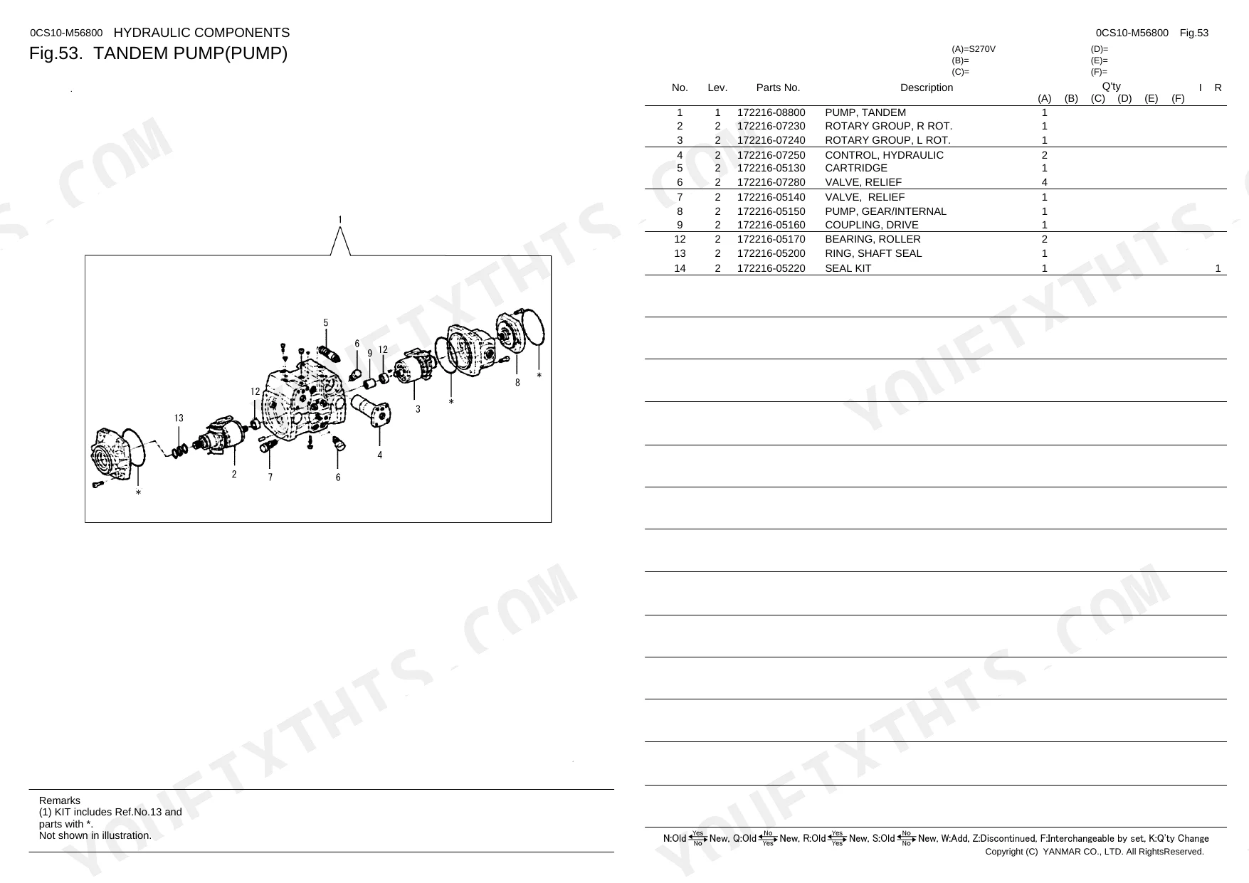
| Hydraulics & 3-Point Hitch | Lift Arm, Hydraulics - Chassis, Hydraulics - Lift Arm, Lift Cylinder, Tilt Cylinder, Tandem Pump, Gear Pump - Single, Gear Pump - Double, Self-Leveling Valve, Main Control Valve, Proportional Valves, Lift Assist Pump and Cylinder, Pump - Hydraulic Quick Coupler, Foot Valve, Auxiliary Coupler Service Kits, Hydraulic Quick Coupler Kit | |
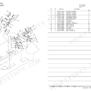
| Loader, Backhoe & Attachments | Attachment Bracket | |
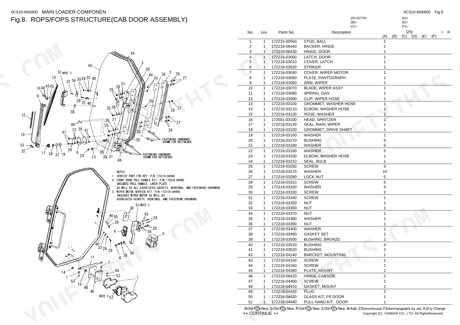
| Body & Operator Station | Chassis, Rops/FOPS Structure, Seats - Standard and Suspension, Seats - Seat Belt Option, Seats - Three-Point Restraint Seat Belt Option, Heater Housing and HVAC Housing Assembly, Condensor, Heater Housing and HVAC Housing Assembly Condensor Housing Assembl, Side Window Kit, Rearview Mirror Kit, Cab Door Kit, Door Completing Package, Am/Fm Radio Kit, Heater/Defroster Kit, Housing Service Parts, Rear Wiper Kit | |
| Decals & Accessories | Decals | |
| Other Components | Restraint Bar, Wheel Drives, Controls - Lift/Tilt and Traction, Tires, Four-Point Lift Assembly, Drive Motors, Ride Control Manifold, Condensor Assembly, Pre-Cleaner Kit, Flasher Kit, Four-Point Lift Kit, Counterweight Kit, Single-Point Lift Kit, Impact-Resistant Door Kit |
Every system also includes no. lev. parts no. description q'ty i r and remarks.
Quick Reference Specifications
| Specification | Value | Page |
|---|---|---|
| Chassis torque | 105 FT/LBS | p. 6 |
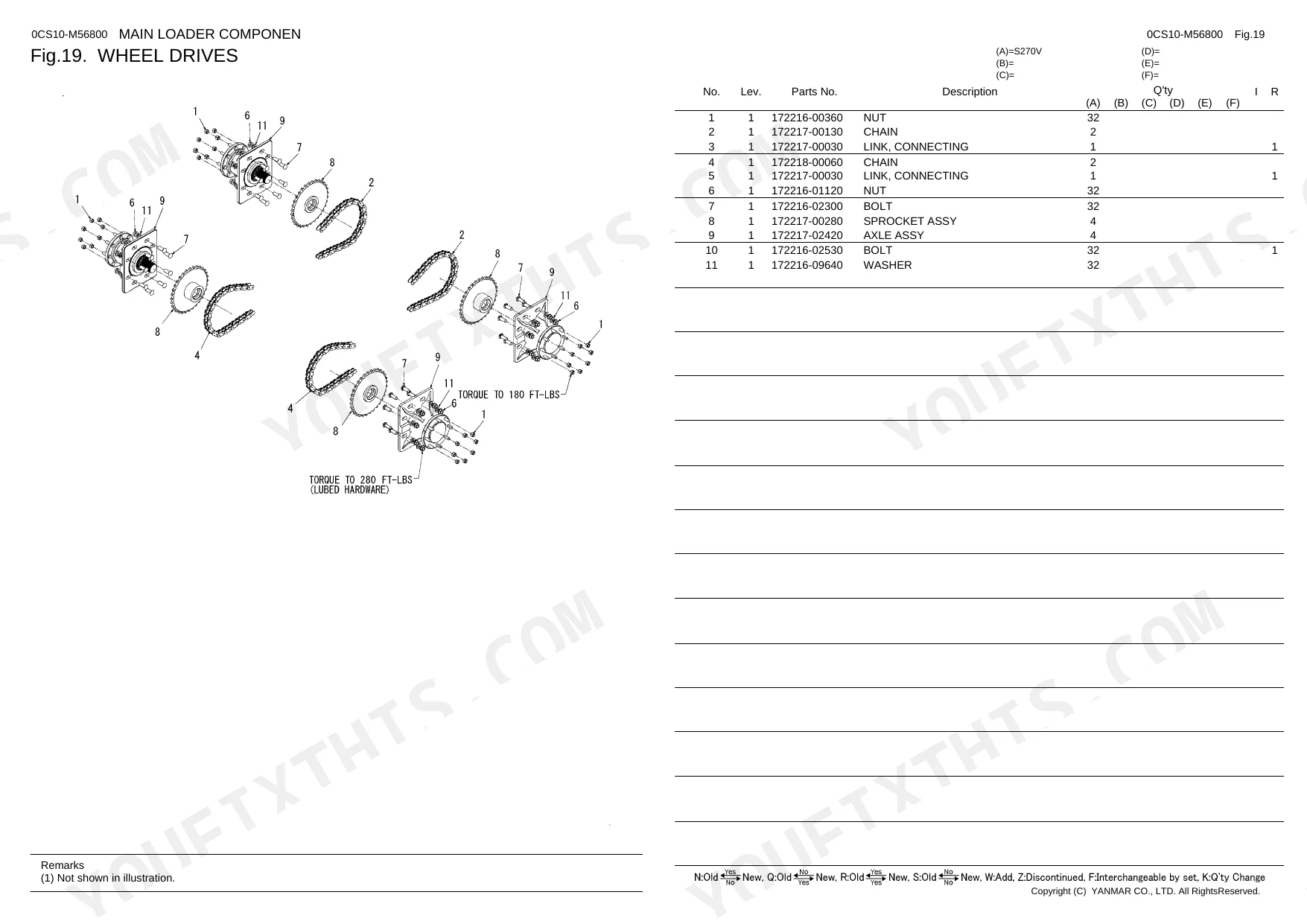
| Wheel Drives torque (lubed hardware) | 280 FT-LBS | p. 29 |
| Fuel Filter replacement part number | 129907-55801 | p. 31 |
| Air Filter replacement part number | 172551-02050 | p. 33 |
| Fresh Air Filter replacement part number | 172551-00010 | p. 8 |
| Hydraulic Hose size | 5/8 X 30 | p. 39 |
| Lift Cylinder Seal Kit replacement part number | 172218-03700 | p. 62 |
| Tilt Cylinder Seal Kit replacement part number | 172218-03670 | p. 63 |
| Starter replacement part number | 129940-77011 | p. 31 |
| Single-Speed Drive Motor R replacement part number | 172217-02500 | p. 64 |
| Single-Speed Drive Motor L replacement part number | 172217-02510 | p. 64 |
| Wheel Drives Torque | 280 FT-LBS | p. 29 |
Yanmar S270V Common Problems This Manual Covers
Yanmar S270V cranks but does not fire and you need the correct replacement fuel filter and starter part numbers
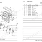
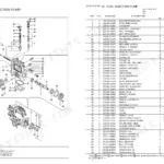
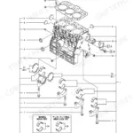
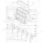
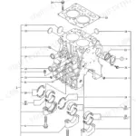
Inspect the engine parts diagram on page 31 for the complete fuel delivery assembly. Order fuel filter part #129907-55801 to resolve restriction issues. If the starter is weak, replace it with part #129940-77011. Verify compatibility with your specific serial number before ordering any replacement parts.
Manual Section: Engine p. 31Main lift arms drift down under load and you need to rebuild the leaking hydraulic lift cylinder
Check the exploded view for the lift cylinder on page 62. Order replacement seal kit part #172218-03700 for the rebuild. Match the internal components against the diagram to ensure you have all required wear rings and wiper seals before starting the tear down.
Manual Section: Lift Cylinder p. 62Machine loses drive power on the right side and requires a new single-speed wheel motor
Review the single-speed drive motors diagram on page 64. Locate the right side drive motor and order replacement part #172217-02500. When installing the new motor, remember that the wheel drives require lubed hardware torqued to exactly 280 FT-LBS as specified on page 29.
Manual Section: Drive Motors(Single-Speed) p. 64Auxiliary hydraulic lines are leaking fluid at the chassis connection and the machine has low flow
Examine the standard auxiliary hydraulics layout on page 39. Identify the leaking 5/8 X 30 hydraulic hose in the diagram and locate its exact replacement number. Before replacing the hose, verify the control valve relief pressure is set to 3200±25 PSI at full throttle.
Manual Section: Hydraulics - Chassis(Standard Auxiliary Hydraulics) p. 39Frequently Asked Questions
What are the torque specs for YANMAR S270V wheel nuts?
The torque specification for the YANMAR S270V wheel nuts is 280 FT-LBS. This applies to lubed hardware. Refer to Fig. 19 for an illustration of the wheel drives. p. 29
What are the replacement specifications for fuel filters?
The replacement fuel filter for the YANMAR S270V engine is part number 129907-55801. This part is listed as 'FILTER, FUEL' in the engine components section. Refer to Fig. 21 for its location. p. 31
How do you fix yanmar S270V cranks but does not fire and you need the correct replacement fuel filter and starter part numbers?
Inspect the engine parts diagram on page 31 for the complete fuel delivery assembly. Order fuel filter part #129907-55801 to resolve restriction issues. If the starter is weak, replace it with part #129940-77011. Verify compatibility with your specific serial number before ordering any replacement parts. p. 31
How do you fix main lift arms drift down under load and you need to rebuild the leaking hydraulic lift cylinder?
Check the exploded view for the lift cylinder on page 62. Order replacement seal kit part #172218-03700 for the rebuild. Match the internal components against the diagram to ensure you have all required wear rings and wiper seals before starting the tear down. p. 62
What format is this manual in?
A 122-page Parts Catalog in searchable PDF format, available the moment you complete checkout. View on computer, tablet, or phone, with no shipping wait.
Can I print this manual?
No restrictions at all. Print individual pages, full chapters, or the entire manual. The PDF is completely unlocked.
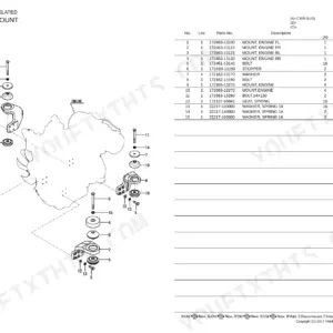
![Yanmar B22-2 C(R)EP, B22-2 P(R)EP, B22-2 P[R], B22-2 C[R] exploded view diagram of the engine mount assembly components.](https://youfixthis.com/wp-content/uploads/2026/06/yanmar-b22-2-to-c-r-crawler-backhoe-parts-catalog-y00s3241-engine-parts-22-150x150.webp)
Reviews
There are no reviews yet.