
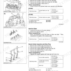
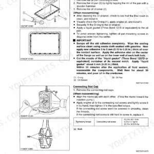
Factory procedures for every system on your compact tractor fill these 406 pages, with 100 of them devoted to step-by-step disassembly and reassembly across the engine, clutch, hydrostatic and manual transmissions, rear axle, brakes, front axle, steering, hydraulics, and electrical. Exploded views and system diagrams show how the parts actually fit. The hydraulic chapter covers the full three-point circuit, control valve operation, and relief valve specs; the electrical chapter lays out complete wiring diagrams, OPC safety circuit logic, and Easy Checker indicator specs. Rear wheel mounting nuts torque to 145 to 150 N·m, front loader pipe joint bolts to 48 to 56 N·m, both straight from Kubota factory data. Stop hunting specs across random forums. Pull it up on a tablet at the machine and get to work.
What's Inside This Kubota B2320, B2620, B2920 Manual
| System | Pages | Key Topics |
|---|---|---|
| General | 13-68 | Tractor Identification (Model Name And Serial Number, Cylinder Number), Handling Precautions For Electrical Parts And Wiring (Battery, Fuse, Connector, Handling Of Circuit Tester) |
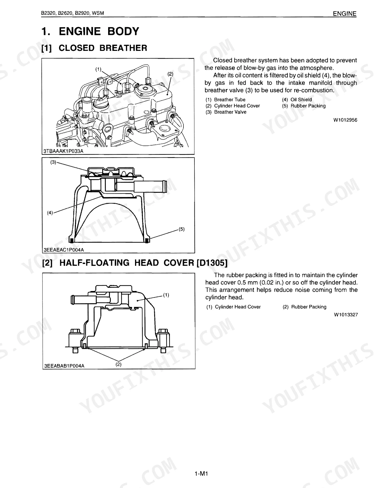
| Sect 1 Engine | 69-142 | Engine Body (Closed Breather, Half-Floating Head Cover, Governor, Half-Floating Head Cover [D1305], Three Lever Type Fork Lever, At Rated Operation, Overloaded Operation) |
| Sect 2 Clutch | 143-162 | Linkage Mechanism |
| Sect 3 Transmission | 163-240 | Structure (Hydrostatic Transmission Type, Manual Transmission Type) |
| Sect 4 Rear Axle | 241-254 | Structure |
| Sect 5 Brakes | 255-272 | Linkage, Operation (During Braking) |
| Sect 6 Front Axle | 273-292 | Structure |
| Sect 7 Steering | 293-318 | Structure (Steering Linkage, Power Steering, Manual Transmission Type, Hydrostatic Transmission Type) |
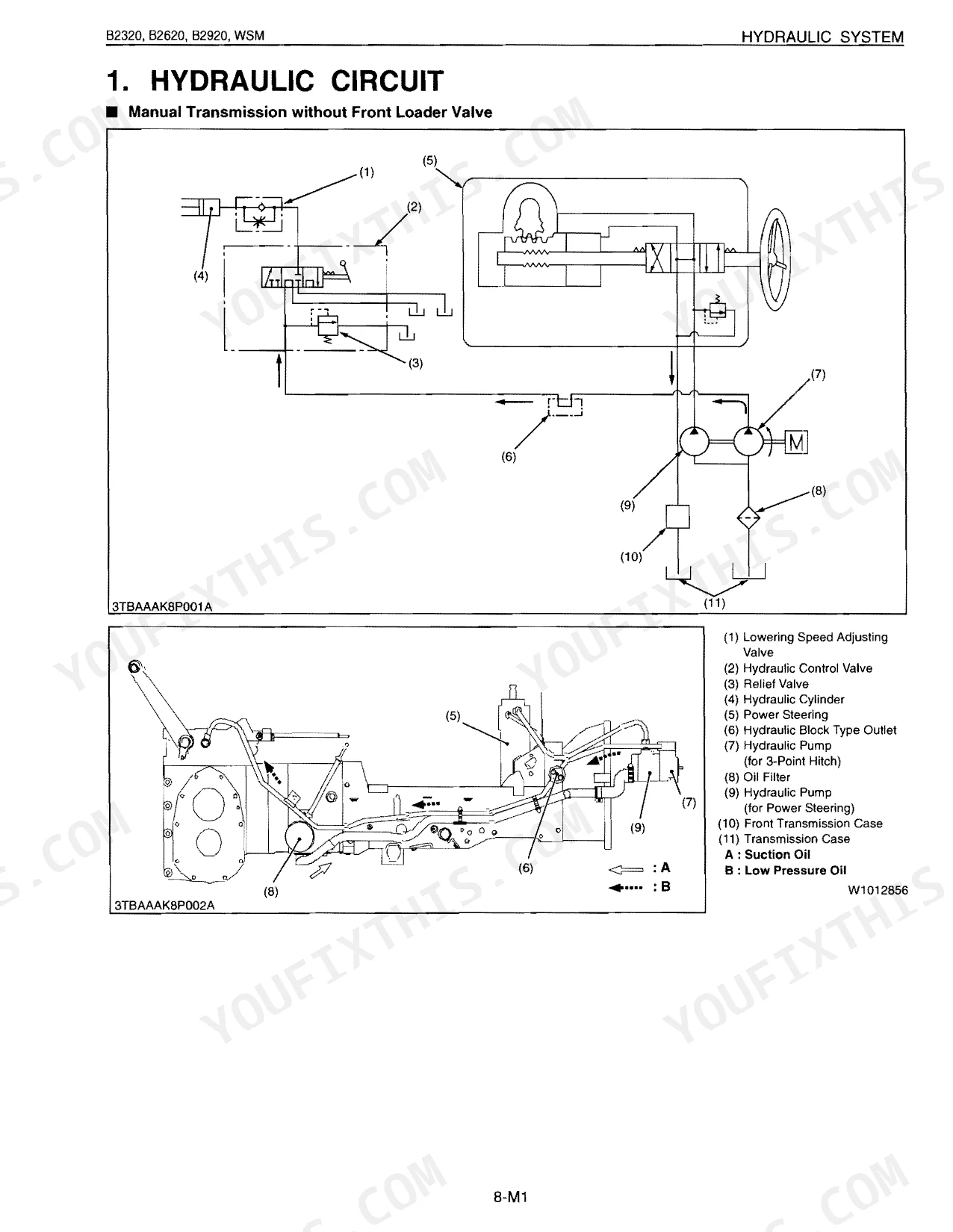
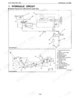
| Sect 8 Hydraulic | 319-356 | Hydraulic Circuit, Hydraulic Pump, Control Valve Assembly (Structure, Operation), Three Point Hydraulic System (Feedback Linkage, Control Valve, Relief Valve, Hydraulic Cylinder) |
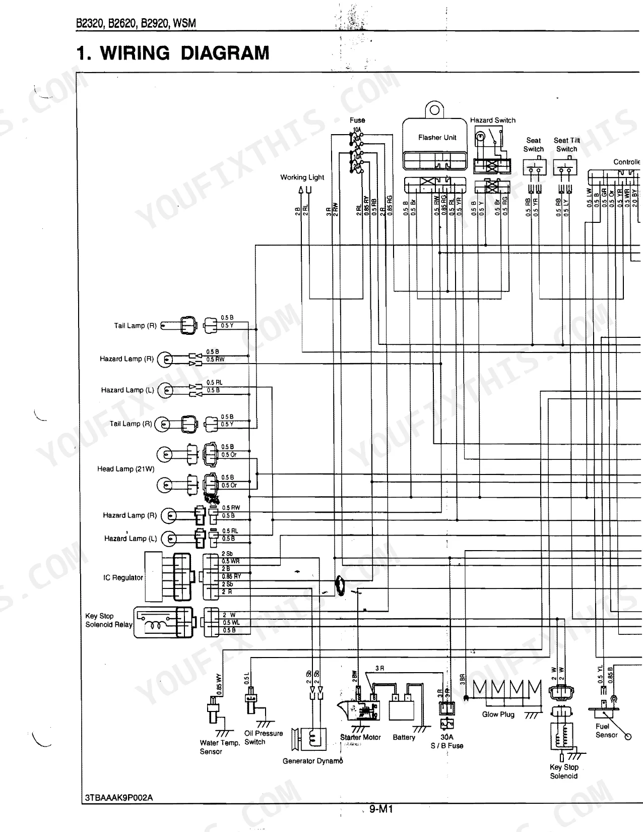
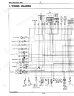
| Sect 9 Electrical | 357-406 | Wiring Diagram, Engine Starting System And Stopping System (Opc System Circuit, Controller, Safety Switch And Engine Condition) |
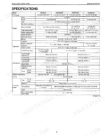
Quick Reference Specifications
| Specification | Value | Page |
|---|---|---|
| All Models | ||
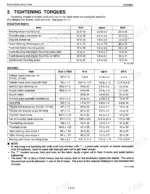
| Joint bolt (Front loader pipe) torque | 48 to 56 N·m (4.9 to 5.7 kgf·m, 36 to 41 lbf·ft) | p. 210 |
| Rear wheel mounting nut torque | 145 to 150 N·m (14.8 to 15.3 kgf·m, 107 to 111 lbf·ft) | p. 194 |
| Seat switch resistance (Operator on the seat) | 0 Ω | p. 387 |
| PTO Switch 1 resistance (PTO gear shift lever in "NEUTRAL" position) | 0 Ω | p. 392 |
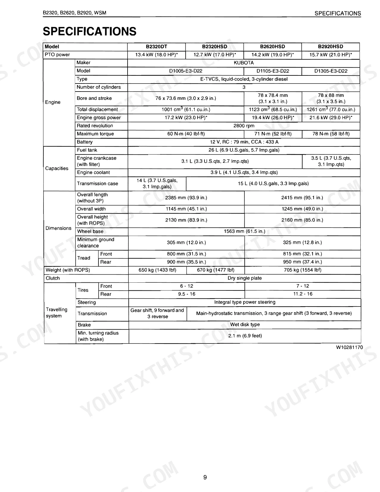
| Min. Turning Radius (with brake) | 2.1 m | p. 9 |
| Max. Lift Force (At lift points) | 615 kg | p. 10 |
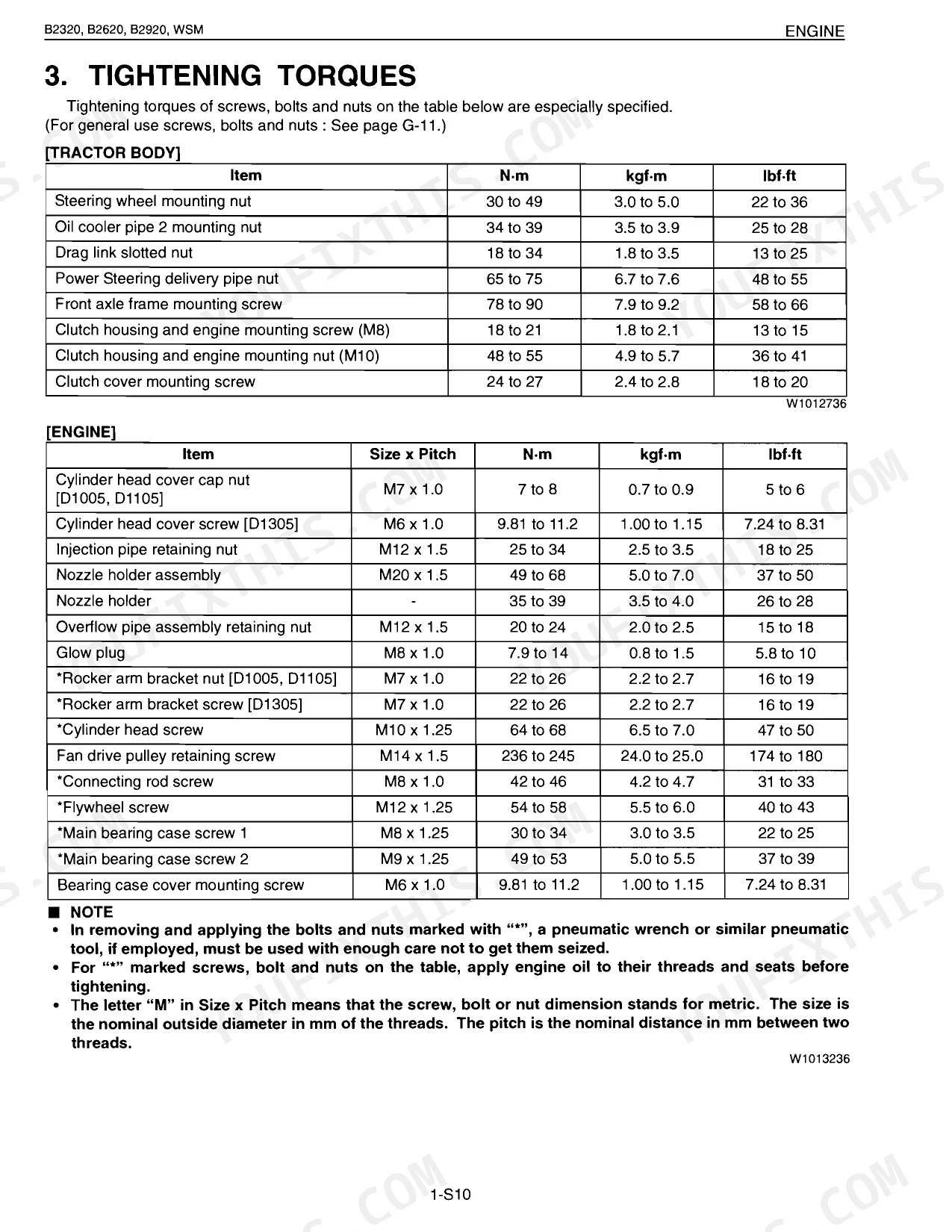
| General Use Bolt Torque (M10, Property class 8.8) | 48 to 55 N·m | p. 26 |
| B2320, B2620, B2920 (Manual Transmission Models) | ||
| Main Shift Switch resistance (Main gear shift lever in "NEUTRAL" position) | 0 Ω | p. 391 |
| B2320HSD, B2620HSD, B2920HSD (HST Models) | ||
| HST safety switch length A | 17.3 to 17.7 mm (0.682 to 0.696 in.) | p. 390 |
| B2320DT, B2620HSD | ||
| Engine Crankcase Capacity (with filter) | 3.1 L | p. 9 |
| B2320DT | ||
| Transmission Case Capacity | 14 L | p. 9 |
| B2320 | ||
| Overall Length (without 3P) | 2385 mm | p. 9 |
Kubota B2320, B2620, B2920 Common Problems This Manual Covers
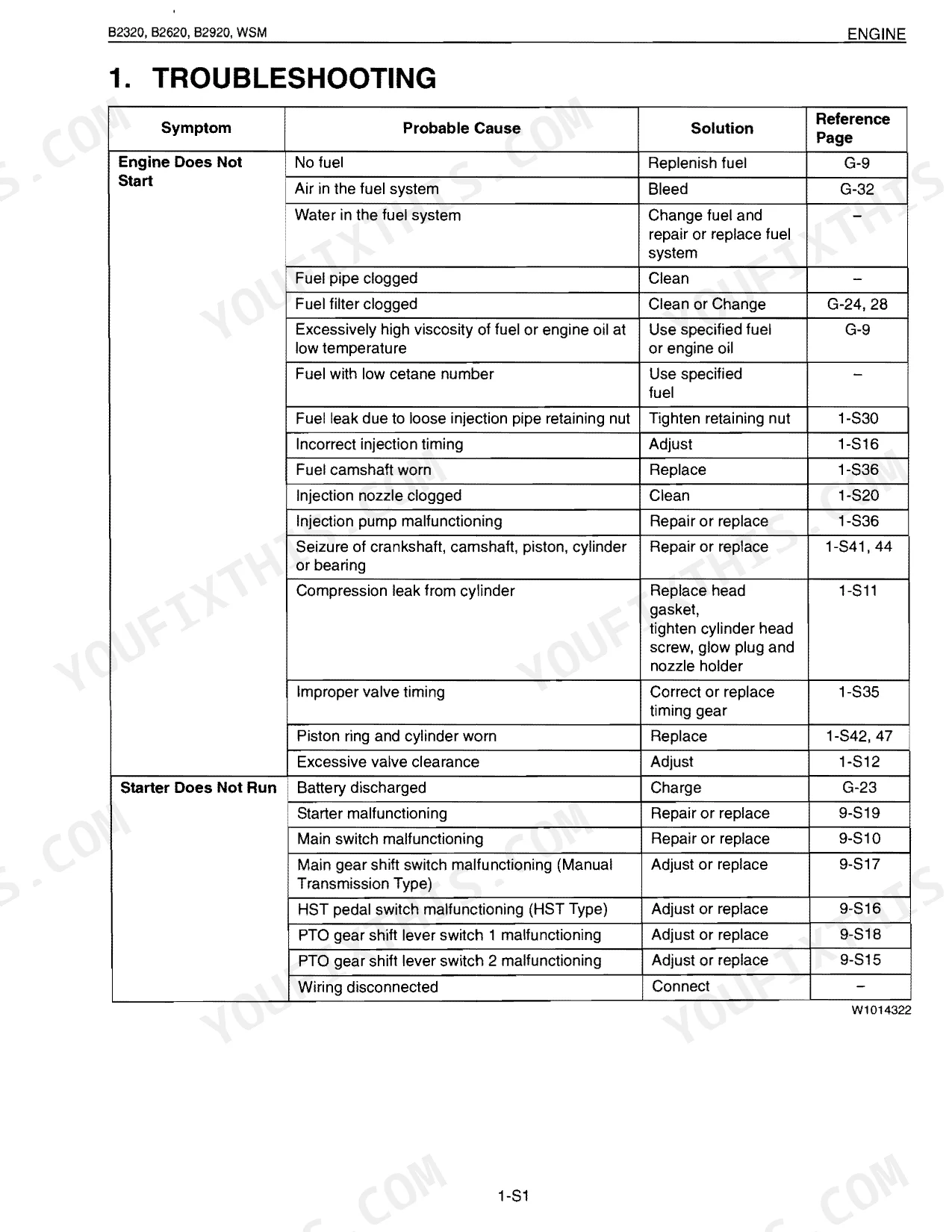
Kubota B2320 cranks but will not start even though the battery is fully charged. p. 387
Inspect the safety interlock circuit components. Test the seat switch resistance as shown on page 387; it must read 0 u03a9 with the operator seated. Verify the PTO switch also reads 0 u03a9 in NEUTRAL. Replace any defective switches to bring the engine starting system back to life.
Manual Section: Sect 9 ElectricalTractor creeps forward or fails to stop smoothly when the hydrostatic pedal is released. p. 390
Work through the HST pedal linkage and return spring, looking for binding or wear. Measure HST safety switch length A; it must fall between 17.3 to 17.7 mm (0.682 to 0.696 in.) on HSD models. Adjust or swap worn parts so the pedal drops back to neutral on its own.
Manual Section: Sect 9 ElectricalThree-point hitch slowly drops by its own weight when the machine is parked under load. p. 10
Pull the control valve assembly and hydraulic cylinder, then check both for internal leakage. Confirm the system still holds its 615 kg maximum lift force at the lift points, per page 10. Replace damaged piston O-rings or worn hitch control valves to stop the drift.
Manual Section: Sect 8 HydraulicMachine experiences uneven braking force between wheels or brake pedal drags during operation. p. 255
Measure brake pedal free travel and adjust the linkage until it sits at 30 to 40 mm. Examine the brake cam and disc for heavy wear or rust. Replace warped cam plates or broken return springs to bring back proper stopping force.
Manual Section: Sect 5 BrakesFrequently Asked Questions
How do I reset the PTO or safety switch on a Kubota B2320/B2620/B2920?
There is no 'reset' procedure for the PTO or safety switches. The manual gives continuity checks instead: if a switch fails its test (not 0 Ω or not infinity, depending on position), treat it as faulty and replace it. The HST safety switch does have one adjustment, its length A, which should sit between 17.3 to 17.7 mm (0.682 to 0.696 in.) when out of factory spec.
What do the warning lights and error codes mean on a Kubota B2320/B2620/B2920?
The Easy Checker carries three indicator lamps: Oil Pressure, Charge, and Pre-heat. The Oil Pressure Lamp lights when engine oil pressure drops low. The Charge Lamp lights when the charging system is not working properly. The Pre-heat Indicator Lamp lights when the key switch sits in the 'Pre-heat' position.
What are the replacement specifications for seat safety switch?
Kubota lists functional replacement criteria for the seat safety switch, not physical dimensions. If the seat switch reads anything other than infinity when released, or anything other than 0 Ω when pushed, it is faulty and needs replacing. The same continuity checks cover the seat tilt switch.
What are the replacement specifications for PTO switch?
Like the seat switch, the PTO switch is judged on function, not dimensions. It should read 0 Ω with the gear shift lever in 'NEUTRAL' and infinity in the 'Mid-PTO and Rear-PTO' or 'Rear-PTO' positions. Any other reading means a faulty switch that should be replaced.
How quickly can I access this Kubota B2320, B2620, B2920 manual after buying?
A 406-page service manual in searchable PDF, ready the moment your checkout completes. Open it on a computer, tablet, or phone with no shipping wait.
Can I print specific sections of this Kubota B2320, B2620, B2920 Service Manual?
No restrictions at all. Print individual pages, full chapters, or the entire manual. The PDF is completely unlocked.
Does this Kubota B2320, B2620, B2920 Service Manual have electrical diagrams?
Complete wiring diagrams are included, covering all electrical circuits, harness routing, and connector pinouts for the Kubota B2320, B2620, B2920.
Document Quality
This document appears to be a scanned PDF with an added OCR text layer, allowing you to search and copy the full text. The text is crisp and easy to read throughout, while diagrams and illustrations are raster images that are clear at normal viewing but may pixelate with high zoom. Pages are generally clean with minimal scan artifacts, though you will find several blank pages interspersed between sections.


Reviews
There are no reviews yet.