


Part of the Case IH Repair Manuals.
910 pages of factory procedures: this Case IH A8000, A8800 Service Manual (OEM #84220561) is the 2012 factory reference for both Cane Harvesters, covering basecutter gearbox, hydraulic pressure control, transmissions, brakes, and the full electrical architecture. Inside: wiring diagrams for harness locations, connector layouts, Scania and FPT Cursor 9 engine circuits, and printed circuit board data. You also get hydraulic schematics, system diagrams, basecutter and chopper manifold repair procedures, connector pinout charts, error code tables, and a troubleshooting section covering dozens of fault scenarios. Set the basecutter main relief valve to 2500 psi (172.3 bar); on the A8800, charge the narrow-front accumulator to 850 psi (58.6 bar) and the large-front to 1700 psi (117.2 bar). Your harvester is down and harvest won't wait. Bookmarked and keyword-searchable; open it on your tablet, walk to the machine, and get to work.
What's Inside This Case IH A8000, A8800 Manual
| System | Pages | Key Topics |
|---|---|---|
| A8000 A8800 Cane Harvesters Service Manual | 1-3 | Topper (Standard), Basecutter Gearbox, Hydraulic System Pressure Control, Transmissions and Brakes, Electrical Component Part Location, Troubleshooting of Faults |
| Safety / Decals | 8-21 | Safety, Personal Safety, Safety in Maintenance, Safety Against Fire, Batteries Safety, Safety Precautions, Legal Obligations, Fire Extinguisher |
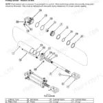
| Special Tools | 22-39 | Universal Puller, Spacer, Compressor Belt Change Tool, AFS600 Service Cable - Radio, Tandem Axle Nut Adjusting Wrench, Basecutter Pinion Bearing Driver |
| Lubrication and Maintenance | 40-111 | Fluids and Lubricants, Fluid Specifications, Lubrication - Oils and Filters, Lubrication and Maintenance Programme, 50 Hours Maintenance, 250 Hours Maintenance |
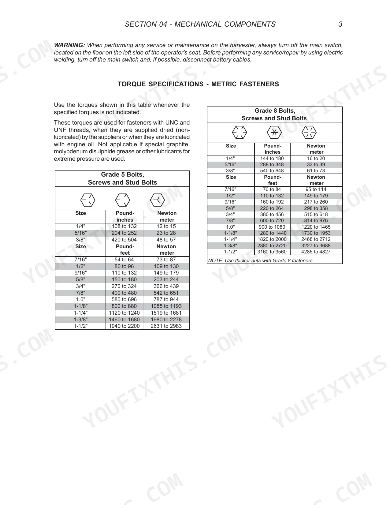
| Mechanical Components | 112-371 | Torque Specification - Imperial Fasteners, Torque Specification - Steel Hydraulic Fittings, Torque Specification - Steel Hydraulic O-Ring Fittings, Special Torque Specifications |
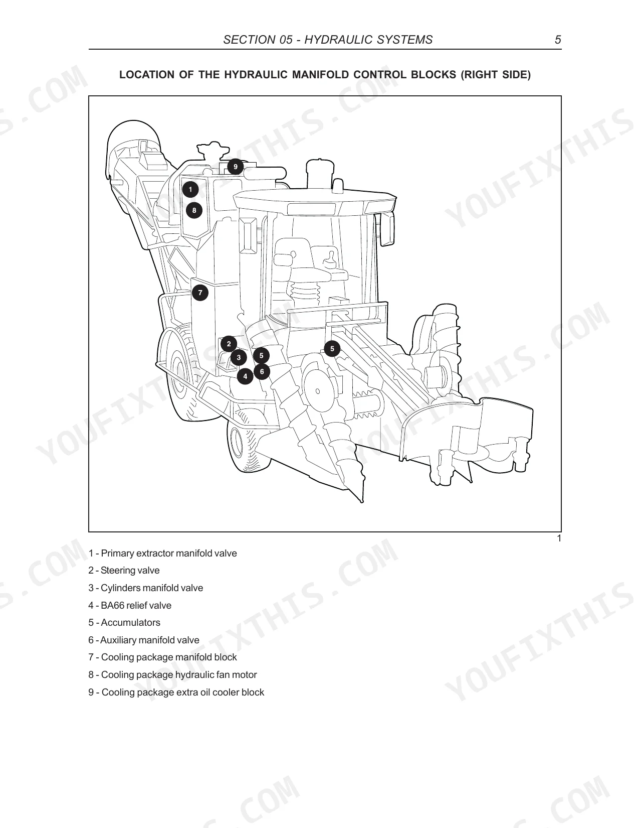
| Hydraulic Systems | 372-427 | Precautions, Basic Principles of the Hydraulic System, Location of the Hydraulic Manifold Control Blocks (Right Hand Side) |
| Hydraulic Components Repair | 428-479 | Basecutter Control Manifold, Primary Extractor Manifold, Chopper Control Manifold, Steering Control Manifold (A8000), Gear Pumps and Motors (Commercial) |
| Scania DC9 Engine Harness | 482-548 | Layout of Harnesses, Glossary, Harness Locations, Electrical Component Part Location, Layout of Connectors, FPT Cursor 9 Engine, Scania Engine, Relay Identification |
| FPT C9 Engine Harness | 549-574 | Rear Right-Side Harness, Elevator Hoses Harness |
| Cabin Harness | 575-624 | Rear Left-Side Harness, Front Harness, Auxiliary Control Manifold Harness, Elevator Control Manifold Harness, Topper Harness, Traction Pump Harness |
| Electronic Modules (SCM) | 625-658 | Machine Grounding Point, Console Harness, Electrical Testing Procedures, Wiring Harness Wire Replacement, Wiring Harness Temporary Repair, Introduction, The Digital Multimeter, Circuit Components - Description and Basic Tests |
| Electrical Circuits | 659-712 | Troubleshooting, Sensors, CAN Network, Interaction with Other Systems |
| Valid for Machines After S/N 800381 and 881100 | 713-812 | - |
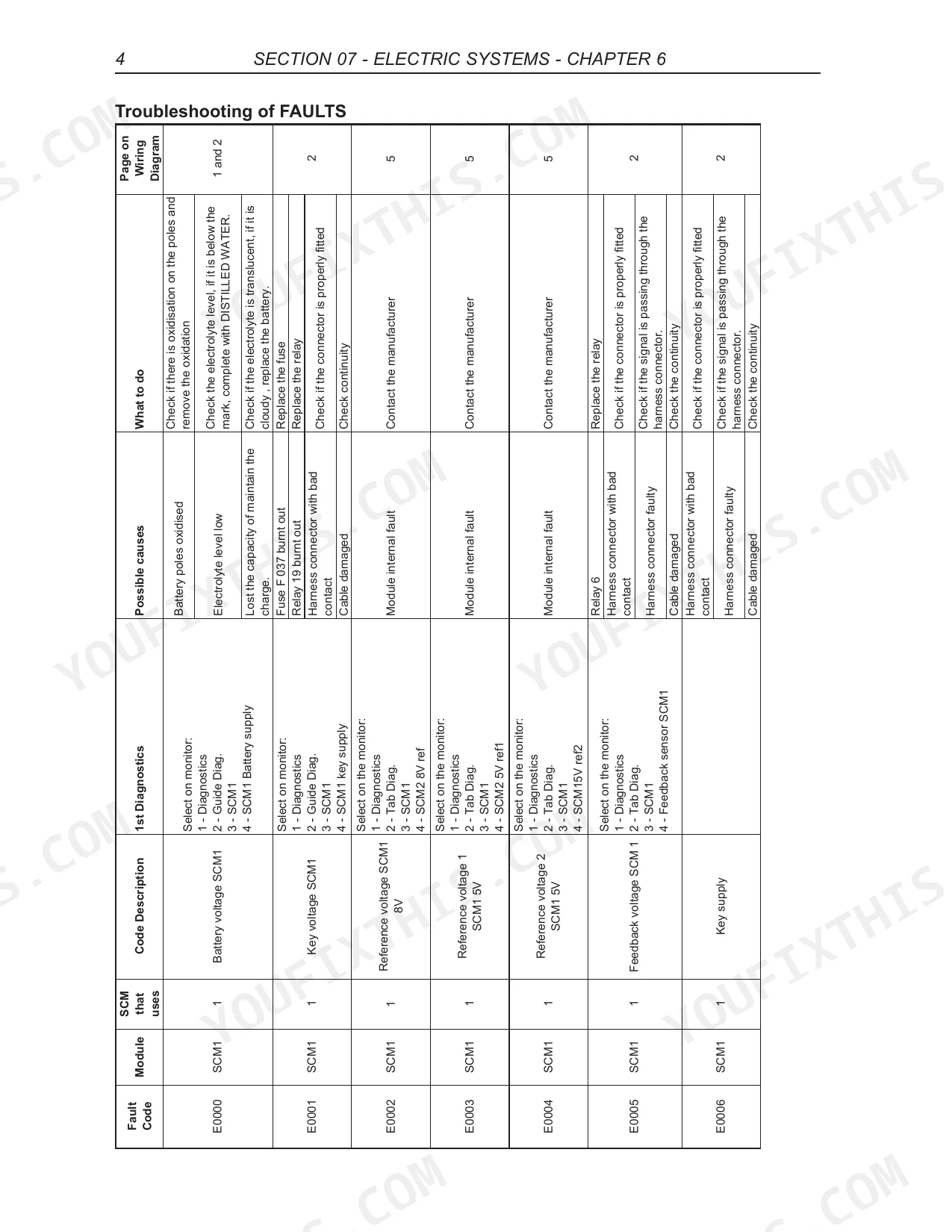
| Troubleshooting of FAULTS | 813-900 | Operation of the A/C Compressor Protection Circuit, Operation of the Starter System Circuit, Operation of the Charging System Circuit, Operation of the Auto Tracker System Circuit, Operation of the Cabin Blower Control Circuit, Operation of the Electronic Traction Electrical Circuit, Operation of the Side Trim Knife Control Electrical Circuit, Operation of the Wiper / Washer System Circuit |
| Table of Codes and Description of Failure Severity | 901-910 | Troubleshooting of ALARMS |
Quick Reference Specifications
| Specification | Value | Page |
|---|---|---|
| A8800 | ||
| Accumulator Nitrogen Pressure (Narrow-front machine) | 850 psi (58.6 bar) | p. 426 |
| Accumulator Nitrogen Pressure (Large-front machine) | 1700 psi (117.2 bar) | p. 426 |
| All Models | ||
| Basecutter main relief valve adjustment | 2500 psi (172.3 bar) | p. 398 |
| Fire risk minimization procedure | Frequent removal of accumulated crop material and checking for overheated machine components; retorque bolts or replace gaskets and seals if oil leaks appear. | p. 11 |
| Fire risk minimization procedure (engine area) | Frequent cleaning of material accumulated of the harvest or residues of the machine. Especially check the engine area and exhaust system. | p. 14 |
| Alarm code A1000 (Basecutter pressure is too high) troubleshooting | Check the reason for the choke / Check on the monitor if the choke pressure is too low, follow the procedure below: 1 - Toolbox 2 - Tab Basecutter 3 - Base C choke pressure | p. 901 |
| Alarm code A1002 (The operator pushed the emergency button) troubleshooting | Turn off the machine and than release the emergency button | p. 901 |
| Basecutter Gearbox Capacity | 9.5 Liters | p. 383 |
| Topper Relief Pressure | 2650 psi | p. 381 |
| Basecutter Relief Pressure | 2500 psi | p. 381 |
| A8000 | ||
| Accumulator Nitrogen Pressure (Topper) | 1200 psi (82.7 bar) | p. 426 |
| Scania DC9 Engine | ||
| Engine Oil Capacity (Scania DC9 Engine) | 27.0 - 34.0 Liters | p. 42 |
Case IH A8000, A8800 Common Problems This Manual Covers
Case IH A8000 or A8800 basecutter or topper fails to fully release pressure after control switch activation
Check the monitor if the choke pressure is too low using the toolbox tab as shown on page 901. Verify the basecutter main relief valve adjustment is set to exactly 2500 psi (172.3 bar) according to page 398. Inspect the accumulator valve and recharge the nitrogen if required.
Manual Section: Faults and Alarms Codes (Comprehensive List) p. 901Harvester fails to start on first attempt and requires 30-second wait and repeated key cycling
Test the ignition key and relay circuits using the troubleshooting procedures. Inspect the hydraulic accumulator pressure valve to ensure it fully releases before restart. Measure the topper accumulator nitrogen pressure and verify it reads exactly 1200 psi (82.7 bar) for A8000 units.
Manual Section: Electric SystemsEngine compartment becomes dangerously hot in dry harvesting conditions with repeated E0042 error codes
Inspect the engine area and exhaust system for accumulated crop material and residues as detailed on page 14. Clean the compartment frequently. Retorque bolts and replace gaskets if oil leaks appear. Verify the Scania DC9 engine oil level is between 27.0 - 34.0 Liters before returning to operation.
Manual Section: Safety / Decals p. 14Basecutter gearbox exhibits excessive noise or vibration during field operation or heavy load harvesting
Drain the fluid and inspect the gears for abnormal wear. Fill the basecutter gearbox to the exact capacity of 9.5 Liters as specified on page 383. Replace the seals if leaks are present and verify the basecutter relief pressure reaches 2500 psi to ensure proper hydraulic function.
Manual Section: Hydraulic Systems p. 383Frequently Asked Questions
How to reset the accumulator pressure valve on a CASE IH A8800 sugar cane harvester?
To adjust the accumulator pressure valve on a CASE IH A8800, you need to connect a pressure gauge and adjust the pressure by adding or removing gas. The specified nitrogen pressures are 850 psi (58.6 bar) for narrow-front machines, 1700 psi (117.2 bar) for large-front machines, and 1200 psi (82.7 bar) for the topper. p. 426
What are the torque specs for the hydraulic motors on the CASE IH A8000 and A8800?
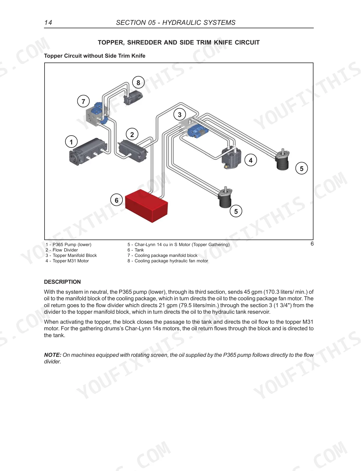
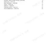
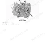
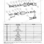
For the assembly of commercial gear pumps and motors, the bolts/nuts should be torqued to 272 N.m (M30, M50, M51 and M350) and 610 N.m (M365). When mounting the hydraulic motor housing to the reduction hub (From chassis A880081 & A800228), the two screws (A) should be tightened to a specific torque of 215 Nm. p. 434
What do error codes on the CASE IH A8000 and A8800 sugar cane harvester mean?
Error codes on the CASE IH A8000 and A8800 sugar cane harvester are composed of a letter (A for alarms, E for faults) and 6 digits (XXXX-XX). The first four digits represent a sequence, and the last two digits represent the severity of the failure. For example, a code of '0' indicates 'Data valid but Above Normal Operating Range - Most severe level'. p. 849
What is the procedure to reset the hydraulic system pressure on CASE IH A8000 series?
To adjust hydraulic system pressure on the CASE IH A8000 series, specific relief valves are adjusted. For instance, the main relief valve for cylinders should be adjusted to 2200 psi (151.7 bar), the charge pump relief valve to 330 ± 25 psi (22.7 ± 1.7 bar), and the IPOR control to 5300 ± 100 psi (356.4 ± 6,9 bar). All pressure settings, except for Eaton transmission pumps and motors, should be +/- 100 psi at 1200 engine RPM. p. 413
What do I get after purchasing this Case IH A8000, A8800 manual?
This is a 910-page searchable PDF ready for immediate download. Works on any device, so pull it up on your phone while you're under the hood. No shipping, no waiting.
Is this Case IH A8000, A8800 Service Manual printable?
Absolutely. No DRM or copy protection. Print the whole manual or just the pages you need. Any home or office printer works.
Does this Service Manual have electrical diagrams?
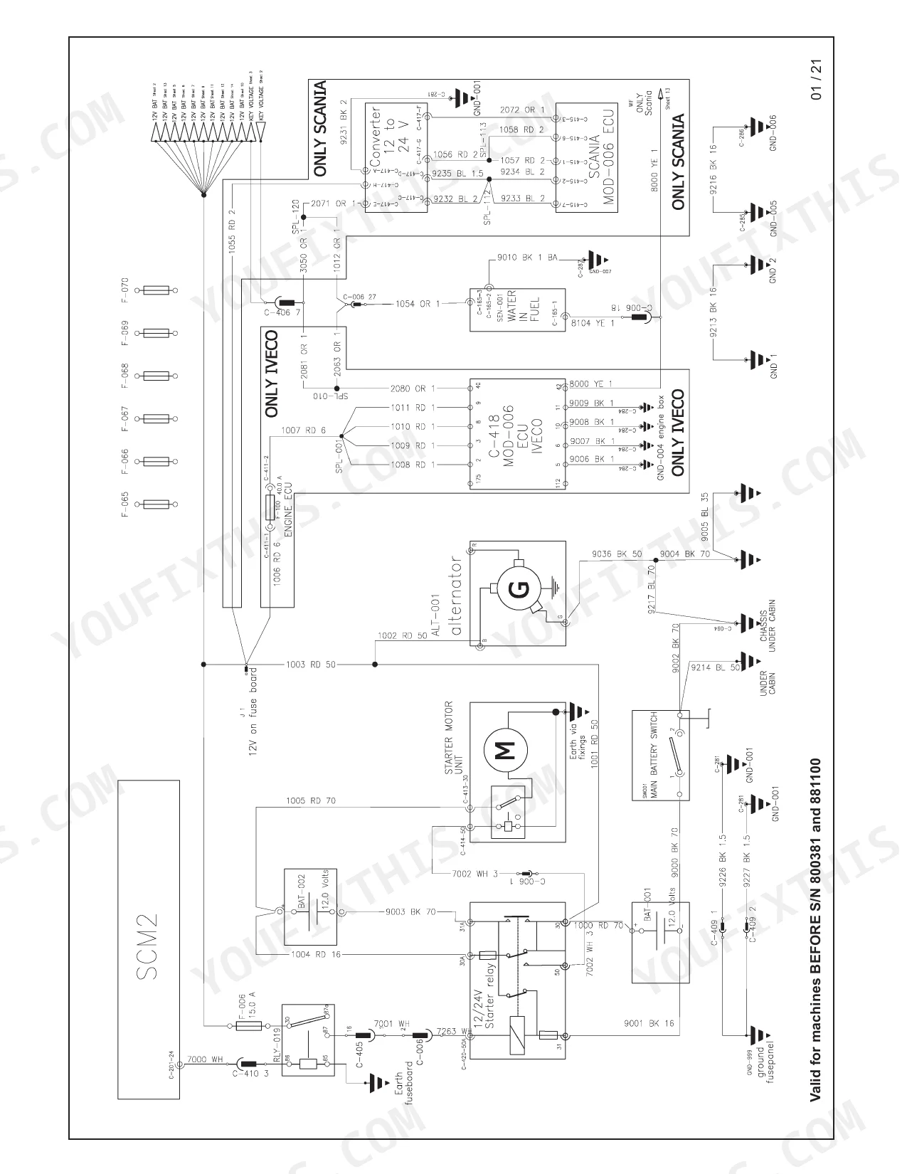
Complete wiring diagrams are included, covering all electrical circuits, harness routing, and connector pinouts for the Case IH A8000, A8800.


Reviews
There are no reviews yet.