


Part of the Case IH Repair Manuals.
All 152 pages of this Case IH DH182, DH212, DH252, DH302, and DH362 Service Manual (OEM #87519333) zero in on one job: keeping your Draper Headers cutting clean and running at factory spec. You get complete hydraulic schematics covering every circuit from draper drive to reel and fore-and-aft, plus a full troubleshooting section and wiring diagrams for the electrical system, lights, and automatic reel speed control. Open to the procedures section and you'll find step-by-step coverage of cutter bar shimming, draper splicing, knife drive, and hydraulic manifold block service. Set your header hydraulic relief valve to 207 bar (3000 psi) and keep fluid temp below 82°C (182°F) before you button it back up. Your draper header doesn't make money sitting in the yard. Grab the PDF, pull it up on your tablet at the machine, and hit the job right the first time.
What's Inside This Case IH DH182–DH362 Series Manual
| System | Pages | Key Topics |
|---|---|---|
| General Information | 11-34 | Precautionary Statements, Safety, Operating and Maintenance Safety, Hydraulic Safety, Welding Safety, Before Transporting |
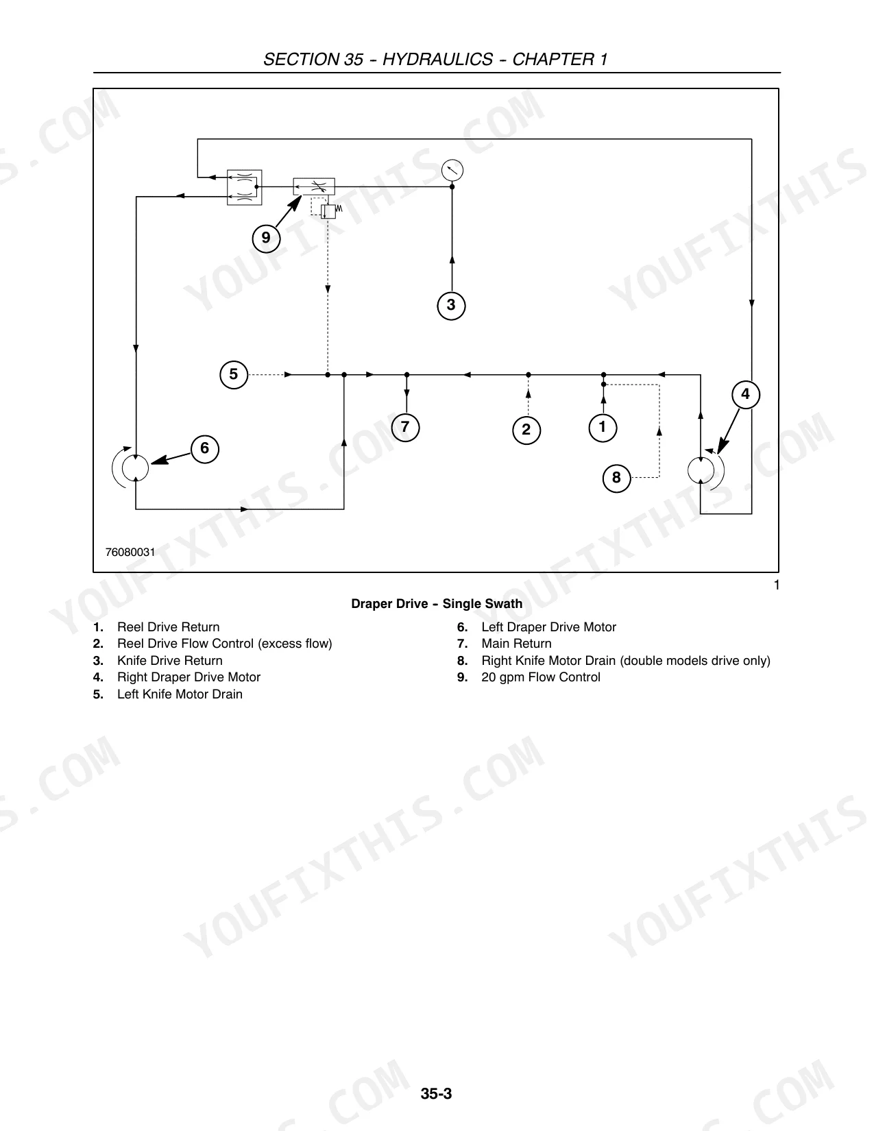
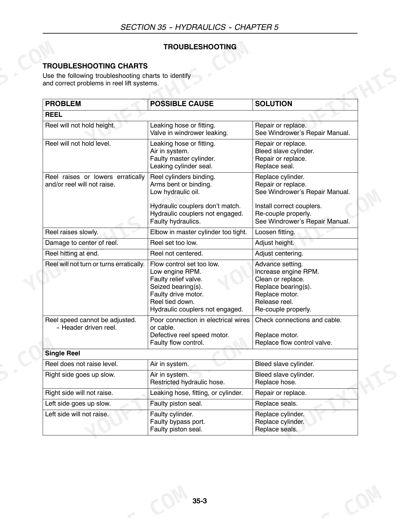
| Hydraulic Schematics & Troubleshooting | 35-62 | Draper Drive, Fore and Aft, Knife Drive, Reel Drive, Reel Lift, Upper Tube, System Tests, Pressure Adjustment |
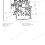
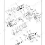
| Hydraulic Pumps, Motors & Components | 63-98 | Hydraulic Motors, Manifold Block, Flow Divider, Draper Flow Control |
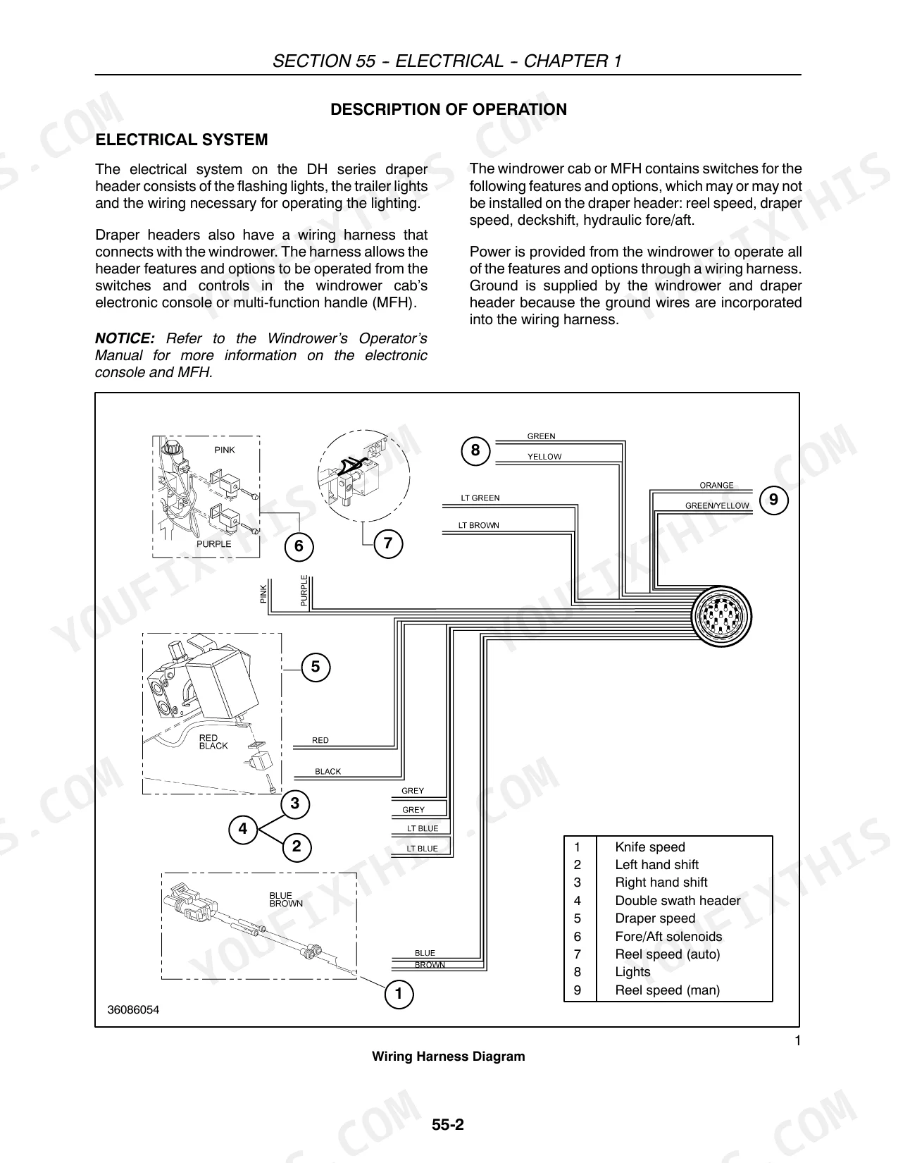
| Electrical | 99-106 | Electrical System, Lights, Remote Speed Control, Sickle Drive Speed Sensor, Automatic Reel Speed Control |
| Attachments | 107-136 | Knife Drive, Cutting Systems, Cutter Bar Shimming, Draper Splicing, Hydraulic Double Swath, Main Draper Decks |
| Decals | 137-152 | - |
Quick Reference Specifications
| Specification | Value | Page |
|---|---|---|
| Relief valve pressure setting | 207 bar (3000 psi) | p. 59 |
| Transport Tire Pressure (225/75R15 radials) | 3.4 bar (50 psi) | p. 16 |
| Header Hydraulic System Pressure Relief Valve Setting | 207 bar (3000 psi) | p. 23 |
| Hydraulic System Maximum Fluid Temperature | 82°C (182°F) | p. 58 |
| Draper Circuit Maximum Flow (single flow control) | 75.8 lpm (30 gpm) | p. 60 |
| Reel Circuit Maximum Flow (single flow control) | 75.8 lpm (20 gpm) | p. 60 |
| Draper/Reel Individual Flow Control Relief Setting | 151.7 bar (2200 psi) | p. 60 |
| Reel Lift Cylinders Collapsed Length | 457 mm (18 in) | p. 86 |
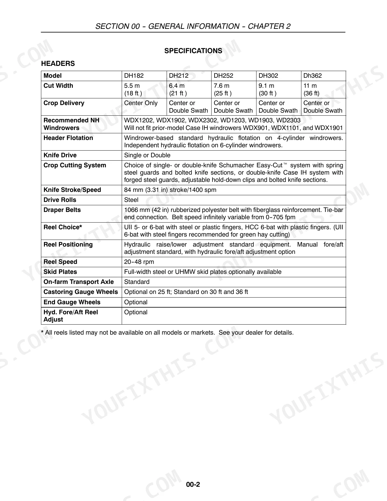
| Knife Stroke/Speed | 84 mm (3.31 in) stroke / 1400 spm | p. 32 |
| Draper Belts Speed | 0-705 fpm | p. 32 |
| Reel Speed | 20-48 rpm | p. 32 |
| DH182 Cut Width | 5.5 m (18 ft) | p. 32 |
Case IH DH182–DH362 Series Common Problems This Manual Covers
Case IH draper header cutter bar flotation inconsistent, crop height uneven across full cut width
Check all runner arm linkages for looseness and inspect turn buckle jam nuts along the support links. Tighten any slack connections and adjust turn buckles evenly side-to-side until flotation is balanced. Verify the float indicator reads zero before field operation. Reference the hydraulic schematic to confirm no relief valve is bypassing at rest. System relief is set at 207 bar (3000 psi); pressure outside that range affects float response.
Manual Section: HydraulicsHeader tilts forward or won't hold ground clearance, AHC cut height control not responding
Inspect the AHC sensors for physical damage and confirm they are enabled on the display. Recalibrate per the troubleshooting procedures starting. Check that the float indicator decal is correctly positioned and the indicator itself reads zero on level ground. If the header still tilts forward after calibration, verify the hydraulic system isn't overheating above 82°C (182°F), which causes erratic cylinder response.
Manual Section: HydraulicsDraper belts slipping, not tracking straight, or decks creep and shift under load
Inspect draper belt tension and tracking adjustment at the deck ends; belts should run centered without walking toward either edge. Check flow control settings against the draper circuit maximum of 75.8 lpm (30 gpm) on page 60. If pressure is reading above the individual flow control relief of 151.7 bar (2200 psi), test the relief valve per the procedure on . Clean any crop buildup from belt edges and deck surfaces that causes uneven drag.
Manual Section: Hydraulics p. 60Knife stalls or won't run, sickle sections breaking at high frequency
Verify knife drive hydraulic pressure is within spec using the knife circuit pressure check on page 59: relief should hold at 207 bar (3000 psi). Confirm knife speed is reaching 1400 spm with an 84 mm (3.31 in) stroke per the technical specs on page 32. If speed is low, check for a partially blocked knife circuit. Inspect sickle sections and guards for bent or cracked sections that increase load; replace damaged sections before re-engaging the drive. See the knife system troubleshooting chart on .
Manual Section: HydraulicsReel moves erratically, won't hold height, or slave cylinders feel spongy
Purge air from the reel positioning slave cylinders using the bleeding procedure on page 86. Collapsed cylinder length should measure 457 mm (18 in); shorter stroke indicates internal leakage or incomplete purge. After bleeding, test reel height and level control. If movement remains erratic, check reel circuit flow per troubleshooting. Confirm reel speed is within the 20-48 rpm operating range shown on page 32.
Manual Section: Hydraulics p. 86Flex arm guards don't rebound after contact, staying compressed against the ground
Press each guard attached to a flex arm down firmly and release. It must spring back 5-20 mm; if it stays flat or rebounds less than 5 mm, the pivot points are either seized or the guard itself is cracked. Remove the guard, clean and lubricate the pivot, and check the flex arm for cracks. Reference attachment service procedures starting on page 107 for guard removal sequence. Replace any guard that fails the rebound check before running in rocky or irregular terrain.
Manual Section: Attachments p. 107Frequently Asked Questions
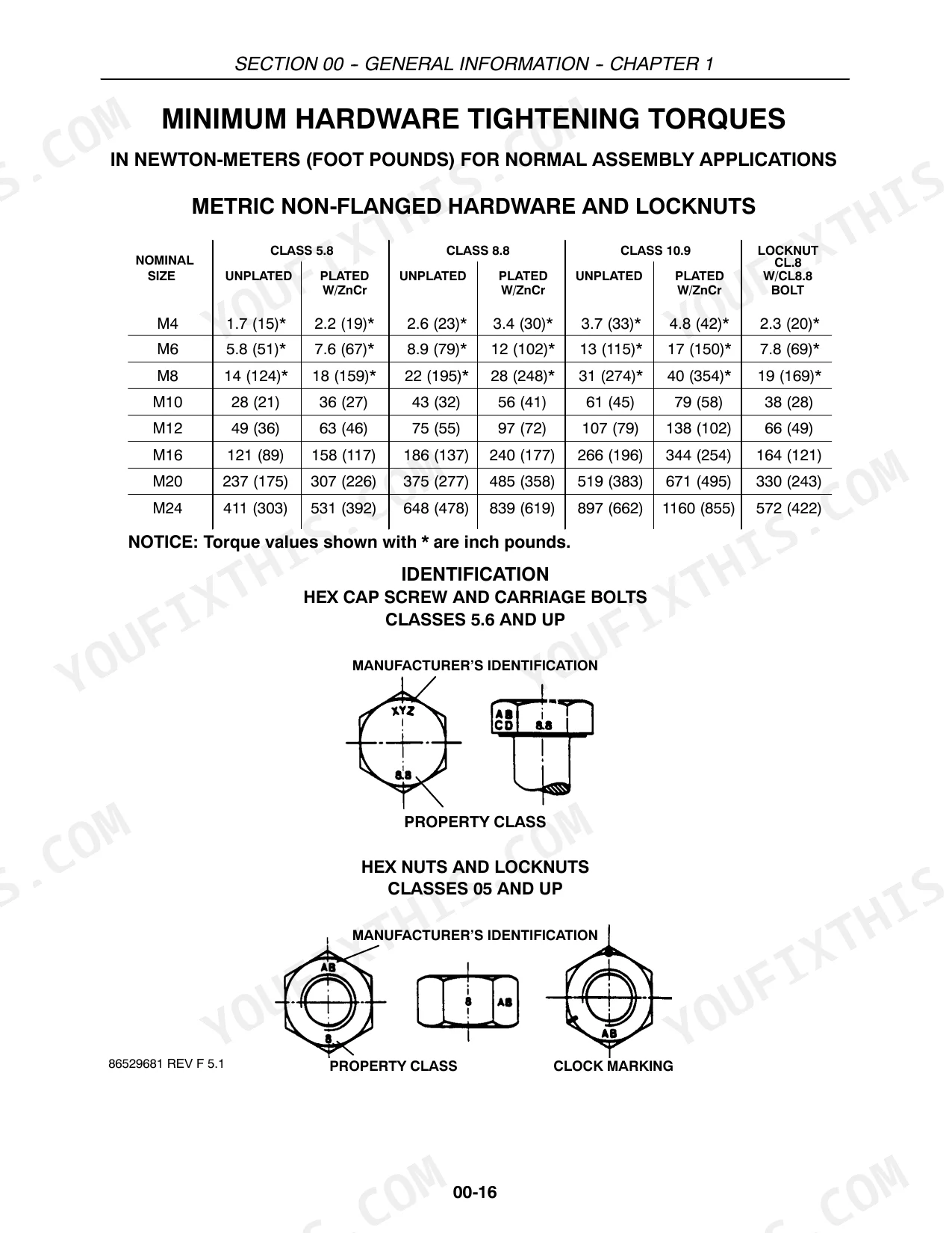
Torque specs for hydraulic motor bolts on draper header?
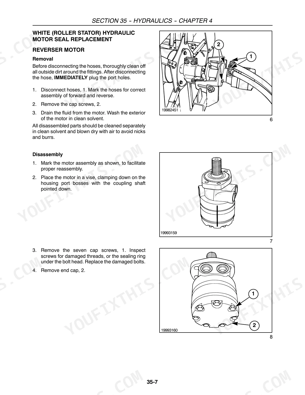
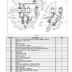
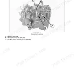
For the White (Roller Stator) Hydraulic Reverser Motor, install the seven cap screws and tighten them in three steps to a final torque of 68 ± 7 N⋅m (50 ± 5 lb ft) using the specified tightening sequence. This procedure is detailed on page 76 of the manual. p. 76
How to adjust hydraulic pressure relief on Case IH DH Series draper header?
To adjust the hydraulic pressure relief valve on the Case IH draper header, jam a wood block in the knife between a guard and a cutting section, start the engine, and engage the header drive. Locate the relief valve on the side of the manifold block. Loosen the lock nut and turn the relief screw 1/4 turn clockwise to increase pressure, or counterclockwise to decrease it. Restart the engine with the knife jammed, engage header drive, check the manifold block gauge, and repeat until 207 bar (3000 psi) is reached. See page 61. p. 61
Is this Case IH DH182, DH212, DH252, DH302, DH362 manual a digital download?
Instant PDF download (4 MB). You get the full 152-page searchable Service Manual immediately after payment. Open it on your laptop, tablet, or phone right in the shop.
Can I print this Case IH DH182, DH212, DH252, DH302, DH362 manual?
Absolutely. No DRM or copy protection. Print the whole manual or just the pages you need. Any home or office printer works.
Does this Case IH DH182, DH212, DH252, DH302, DH362 manual cover the hydraulic?
Full hydraulic system diagrams are included, covering circuits, valve locations, and hydraulic component specs for the Case IH DH182, DH212, DH252, DH302, DH362.


Reviews
There are no reviews yet.