


Part of the Case IH Repair Manuals.
Need factory-level repair data for your Case IH JX1060–JX1075 series tractor? This 1,204-page service manual PDF (OEM #6-62730) covers all five variants: JX1060V, JX1070V, JX1075V, JX1070N, and JX1075N. Inside: complete wiring schematics for every circuit variant, hydraulic system diagrams for the rear lift and auxiliary valves, a full troubleshooting section with fault code decoding for the Power Shuttle and 4WD control unit, and page after page of torque specs and calibration data. You get cross-sectional exploded views of every major drivetrain assembly, from the gearbox through the front axle epicyclic final drive. Set the rear hydraulic lift pressure relief valve to 180 bar; your JX1070V or JX1075V clutch takes cerametallic lining plate, not the organic agglomerate spec for the JX1060V. Stop digging through forum threads for specs that may not even apply to your variant. Bookmarked and keyword-searchable: jump to any diagram or fault code instantly.
What's Inside This Case IH JX1060V–JX1075N Series Manual
| System | Pages | Key Topics |
|---|---|---|
| General Guidelines | 7-12 | Safety Regulations, Consumables |
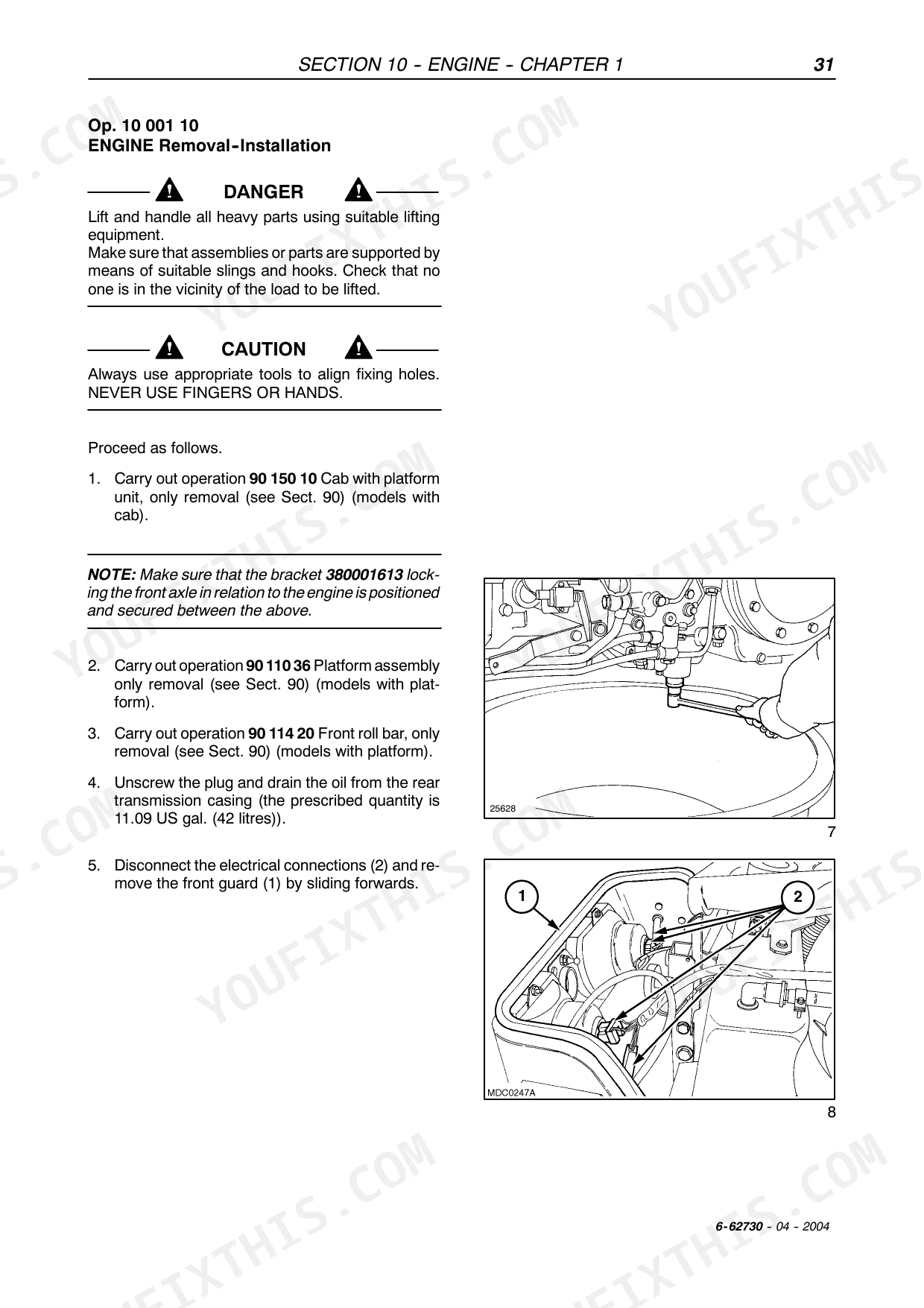
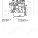
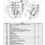
| Engine | 13-114 | 001 10 Engine. Removal -- Installation, 001 30 Compression. Test, 001 54 Engine. Disassembly -- Assembly, 101 53 Valve Guides. Replacement, 101 60 Injector Sleeve. Replacement |
| Clutch | 115-138 | Tightening Torques, Tools, Cross--Sectional Views, Fault Diagnosis, 110 10 Clutch -- Removal--Installation, 110 30 Dual Disk Clutch 11î/11î Test Bench Overhaul |
| Transmissions | 139-338 | Transmission and Range Gear (Data, Tightening Torques, Tools, Cross--Sectional Views, Description and Operation, Fault Diagnosis, 118 10 Rear Transmission Casing--Gearbox. Removal -- Installation, 118 12 Rear Transmission Casing--Gearbox. Removal -- Installation, 118 85 Gearbox Transmission Casing. Disassembly -- Assembly, 130 10 Gearbox Control Lever. Removal -- Installation, 130 11 Range Gear Control Lever. Removal -- Installation, 130 52 Shuttle Control Lever. Removal -- Installation) |
| Drive Lines | 339-408 | Main Data, Tightening Torques, Tools, Cross-Sectional Views, Operation and Hydraulic Diagrams, Fault Finding |
| Front Axle Mechanical Transmission | 409-478 | Main Data, Tightening Torques, Tools, Front Axle Gear Unit Diagram, Cross-Sectional Views and Components |
| Rear Axle Mechanical Transmission | 479-510 | Main Data, Tightening Torques, Tools, Cross-Sectional Views, Description and Operation, Fault Finding, Removal-Installation-Overhaul |
| Mechanical Power Take--Off | 511-526 | Main Data, Tightening Torques, Cross--Sectional Drawings, Description and Operation, Troubleshooting, Mechanical Power Take--Off. Disassembly--Assembly |
| Brakes | 527-546 | Main Data, Tightening Torques, Cross-Sectional Views, Tools, Description and Operation, Fault Diagnosis, Right or Left-Hand Brake. Removal -- Installation |
| Hydraulic Systems | 551-758 | Rear Mechanical Hydraulic Lift, Main Data, Tightening Torques, Special Tools, Cross-Sectional Views, Description and Operation, Troubleshooting |
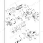
| Steering | 759-794 | Constant Flow Gear Pump |
| Axles and Wheels | 795-812 | Data, Front Wheel Track Diagram, Cross-Sectional Views, Tightening Torques, Tools, Fault Diagnosis, Disassembly-Assembly -- Wheel Axle Hub, Removal-Installation -- Front Axle |
| Cab Air Conditioning System | 813-854 | Safety Regulations, Main Specifications, Tools, Operating Principles, Components of Cab Air Conditioning System, Cab Controls, Operation Control and Cooling |
| Electrical System | 855-1180 | Instruments (Analog Instruments, Transmitters, Sensors and Switches, Electronic Module Instruments, Maintenance) |
| Cab | 1181-1204 | Bonnet, Instrument Panel Lower Guard, Platform Assembly, Front Roll Bar, Cab Windows, Cab Ceiling Fitting |
Quick Reference Specifications
| Specification | Value | Page |
|---|---|---|
| All Models | ||
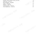
| Eccentricity of drive shaft | 0.1181 in. (3 mm) | p. 24 |
| Diameter of drive shaft at bushings | 1.2588 to 1.2598 in. (31.975 to 32.000 mm) | p. 24 |
| Pressure relief valve setting (Rear Hydraulic Lift) | 7.0866 psi (180 bar) | p. 551 |
| Cylinder safety valve setting (Rear Hydraulic Lift) | 8.2677 to 8.4645 psi (210 to 215 bar) | p. 551 |
| Replacement of seals | All seals must be replaced | p. 63 |
| Sealing compound thickness (transmission) | approx. 0.0787 in. (2 mm) | p. 480 |
| Replacement of ground cable | Replace the ground cable if voltage exceeds 0.2 V | p. 896 |
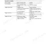
| Solution for 'The lift does not rise' due to 'Clogged oil filter' | Replace filter | p. 565 |
| Solution for 'The lift does not rise' due to 'Control valve jammed in discharge position' | Release control valve | p. 565 |
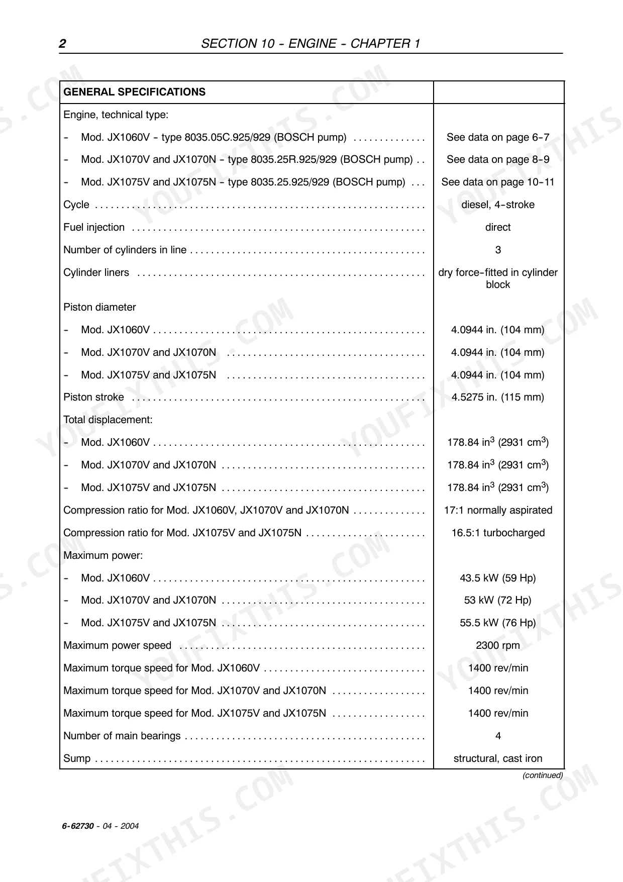
| Engine Sump Capacity (without filter) | 1.76 US gal (6.7L) | p. 12 |
| JX1060V | ||
| Driven plate lining material for main transmission clutch | organic agglomerate | p. 115 |
| JX1070V/N and JX1075V/N | ||
| Driven plate lining material for main transmission clutch | cerametallic | p. 115 |
Case IH JX1060V–JX1075N Series Common Problems This Manual Covers
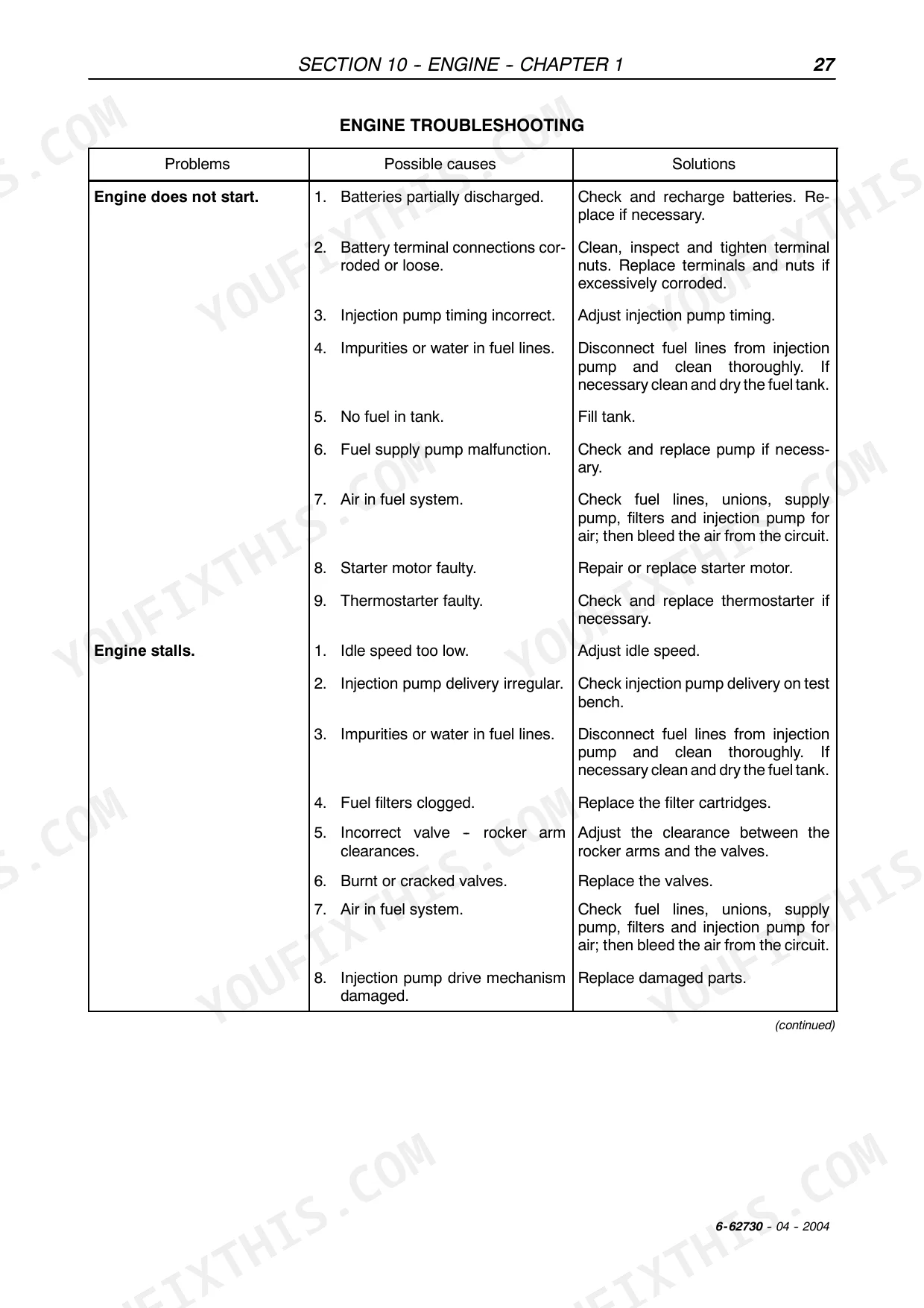
Case IH JX1070V engine stalls under load or cranks but won't fire
Check fuel supply pump against the troubleshooting chart on . Start with the fuel filter: if clogged, replace it before pulling the pump. Measure drive shaft eccentricity (max 0.1181 in. / 3 mm) and shaft-to-bushing assembly clearance (0.0019 to 0.0039 in. / 0.050 to 0.100 mm). Replace the fuel supply pump if measurements are out of spec per page 41.
Manual Section: Engine Troubleshooting p. 39Transmission slips when shifting under load, requires multiple attempts to engage gear
Inspect clutch driven plate thickness per page 119. For JX1070V/N and JX1075V/N, plate thickness should be 0.3779 to 0.4094 in. (9.6 to 10.4 mm); JX1060V spec is 0.3818 to 0.4055 in. (9.7 to 10.3 mm). Measure each plate and replace any worn to or past the limit. Adjust clutch levers and control linkage after disk replacement.
Manual Section: Clutch Troubleshooting p. 119Hydraulic lift won't raise implement or rises too slowly under full load
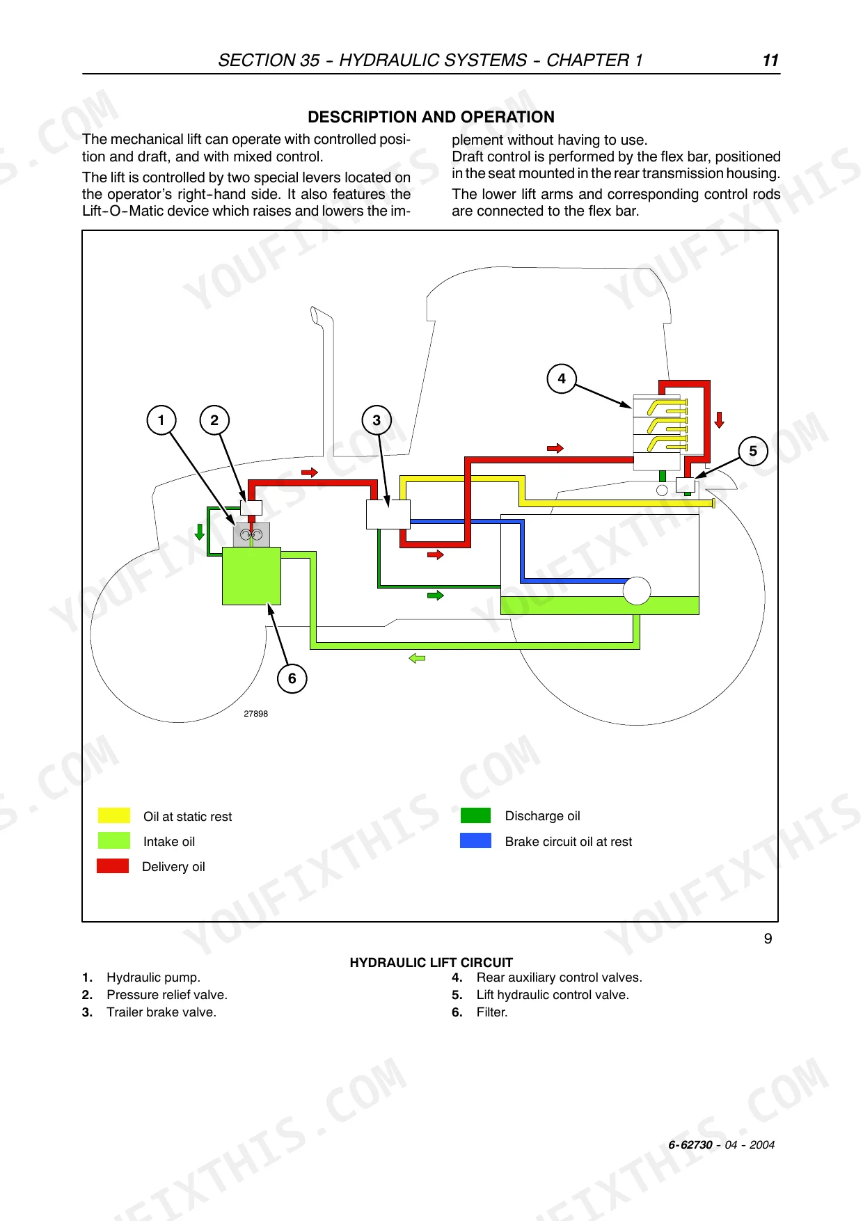
Replace the oil filter first; a clogged filter blocks flow before the pump even gets tested. Verify the pressure relief valve is set to 180 bar. Inspect all hydraulic seals and replace defective ones per the procedures on page 565. If the lift still won't rise after filter and seal service, overhaul or replace the pump.
Manual Section: Hydraulic Lift Troubleshooting p. 565Steering is stiff in one direction or jolts when turning through a headland
Check the hydrostatic steering troubleshooting chart on page 765. Inspect the control cylinder seal: if leaking, replace it. For stiffness or difficulty in one direction, verify hydraulic pump pressure and pressure relief valve calibration per page 766. Clean cylinder safety valve seats if deposits are causing inconsistent response. Replace the control valve if internal leakage persists after seal and valve service.
Manual Section: Hydrostatic Steering Troubleshooting p. 765Instrument cluster warning lights flicker randomly, dashboard resets for no apparent reason
Inspect all wiring harness connectors for corrosion and reseat them firmly. Measure voltage drop across the main ground strap: above 0.2 V means the cable needs replacement (page 896). Clean ground contact points at the battery, chassis, and engine block. Run the starting system fault diagnosis for additional fault codes before replacing any modules.
Manual Section: Electrical System Starting System Fault DiagnosisFrequently Asked Questions
How to reset error codes on Case IH JX1060V tractor?
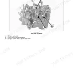
To reset error codes on the JX1060V tractor, access the H8 menu using the diagnostic unit 380000282. Press and hold down key B (4) for 5 seconds until "ERASED" is displayed, then release the key. Finally, switch off the engine by turning switch (1) to A (OFF) and wait for at least 2 seconds to save the new configuration. p. 211
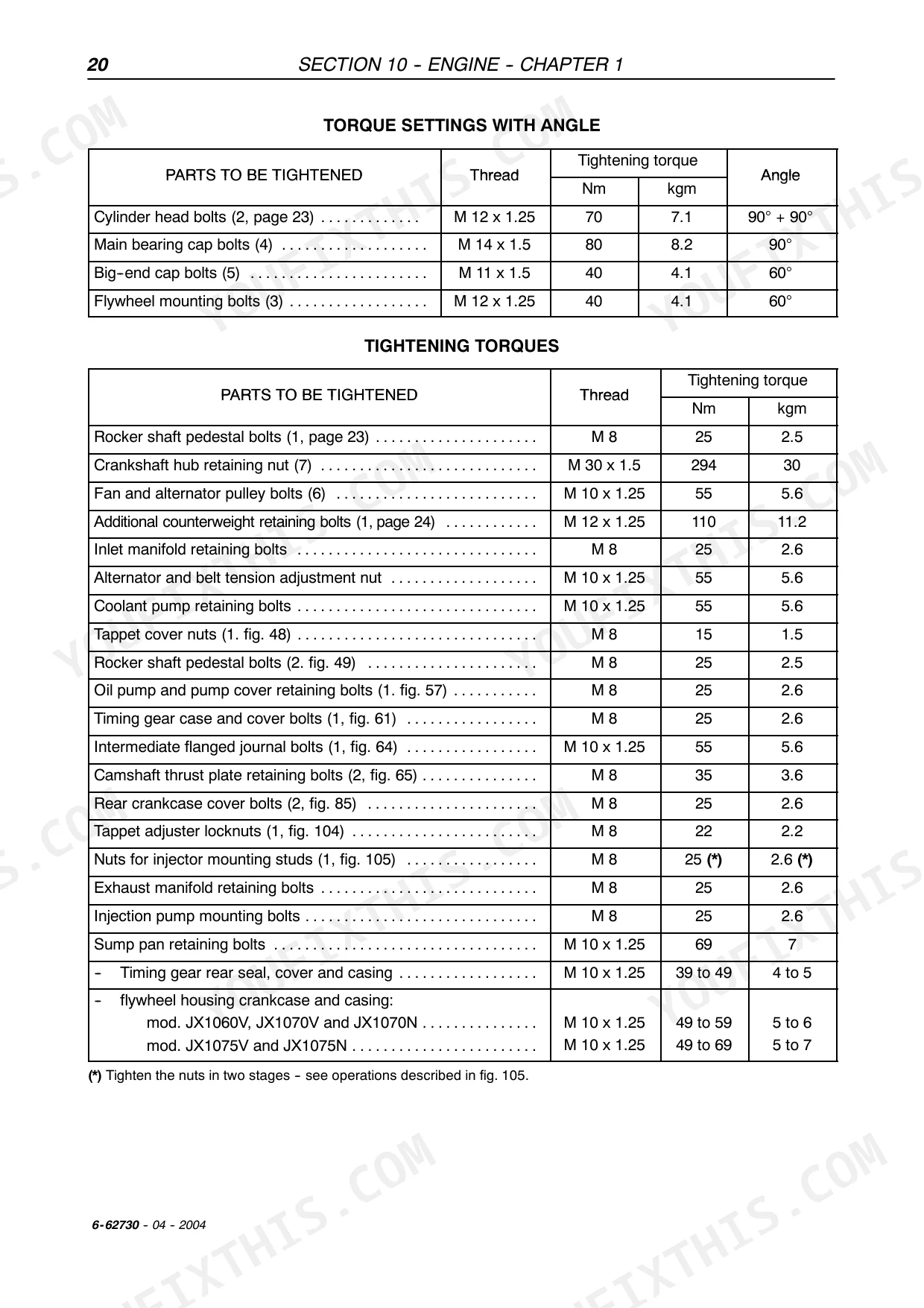
Torque specs for engine bolts on Case IH JX1070V tractor?
The torque specifications for engine bolts on the Case IH JX1070V tractor vary by component. For instance, cylinder head bolts (M12 x 1.25) require 70 Nm (7.1 kgm) plus two 90° turns, while main bearing cap bolts (M14 x 1.5) require 80 Nm (8.2 kgm) plus a 90° turn. Big-end cap bolts (M11 x 1.5) are tightened to 40 Nm (4.1 kgm) plus a 60° turn. p. 32
How to reset maintenance light on Case IH JX1060V?
To reset the "hours worked" on the digital multi-indicator panel, which might be related to a maintenance light, use the CAL (1, fig. 5) pushbutton to select the "hours worked" function on sector (1). This function can be zero-set a maximum of 3 times within the first 100 hours worked. p. 1171
What are the replacement specifications for Fuel pump?
The manual specifies that the fuel pump is "with double diaphragm" and has a minimum fuel flow rate of "100 litres/hour" with the pump shaft rotating at 1600 rpm. However, specific replacement specifications for the fuel pump itself are not provided, only troubleshooting steps to check and replace it if faulty (page 39). p. 16
How will I receive this Service Manual?
Instant PDF download. You get the full 1204-page searchable Service Manual immediately after payment. Open it on your laptop, tablet, or phone right in the shop.
Can I print specific sections of this manual?
Yes. The PDF has no DRM restrictions, so print any page or section you need for your shop. Works with any standard printer.
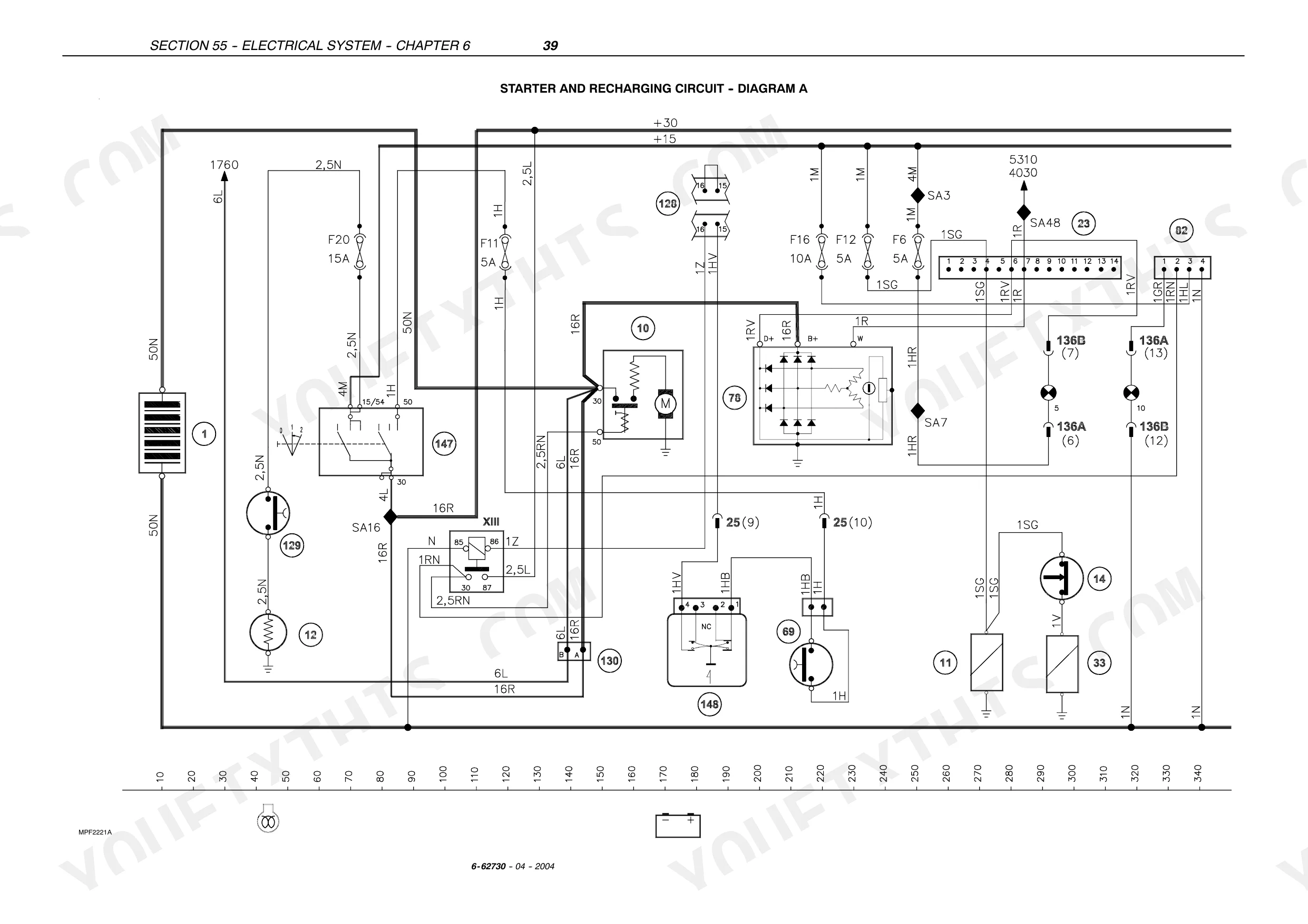
Does this Case IH JX1060–JX1075 Series manual include hydraulic schematics?
Full hydraulic system diagrams are included, covering circuits, valve locations, and hydraulic component specs for the Case IH JX1060–JX1075 Series.


Reviews
There are no reviews yet.