


Part of the Case IH Repair Manuals.
All 121 pages of this Case IH L103–L795 series service manual PDF (OEM #60034449) cover seven farm loaders: L103, L104, L105, L106, L107, L108, and L795. Inside you get hydraulic schematics tracing every Compact Valve Unit function module and hose routing, wiring diagrams for the standard loader, Live3, and all-hydraulic-function configurations, plus a troubleshooting table that takes you from symptom to root cause without guesswork. Step-by-step cylinder rebuild procedures for both MSL and NSL tilt loaders are backed by full exploded views of each assembly. Torque your Lock & Go handle to 22 Nm; set the SV01 selector valve fastener to 40 Nm. Your loader is sitting idle. Grab the factory numbers, not a forum post. Bookmarked by section, keyword-searchable, and sized to open on your tablet right beside the machine.
What's Inside This Case IH L103–L795 Series Manual
| System | Pages | Key Topics |
|---|---|---|
| Introduction | 4-8 | Necessary Additional Documentation, Identification (Model and Serial Number), Alignment Reference, Setting Joystick Position, Subframe Identification |
| Description and Definitions | 9-22 | Loader Overview, Component Identification, Model Nomenclature, Loader Types (MSL/NSL), Subframe Description |
| Safety Instructions | 23-41 | Explanation of Warning Levels (Symbol Explanation, Responsibility), Installing the Loader, Joystick Operation |
| Installation - Subframe | 42-43 | Installation Preparation - Subframe, Installation – Subframe on Tractor, Installation Checks – Subframe Installation |
| Installation – Front Loaders | 44-55 | Installation Preparation, Front Loaders (Lock & Go, Position Indicator, Position Indicator Setting) |
| Installation – Control System | 56-61 | Hose Kit, Compact Valve Unit |
| Service - General | 62 | Tractor's Own Joystick |
| Service – Subframe | 63 | Subframe Hardware, Specified Torque, Installation Instructions, Subframe Damage, Tractor Damage, Original Spare Parts |
| Service – Front Loaders | 64-69 | Lubrication, Tool Carrier, Loaders, Bearing Box |
| Service - Loader Hydraulics | 70-81 | Hydraulic System, Hoses and Connectors, Main Hose Kit, Boom Suspension, Compact Valve Unit (Cvu) with Associated Function Modules |
| Service - Cylinders | 82-104 | Tilt Cylinder - Mechanical Self Levelling Loader, (Msl), Tilt Cylinder - Non-Self Levelling Loader (Nsl), Lift Cylinder |
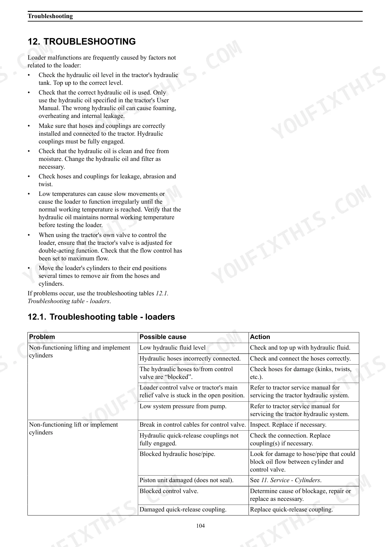
| Troubleshooting | 105-109 | Troubleshooting Table - Loaders |
| Tightening Torques | 110 | Subframe Hardware, Fixed Components, Screws, Fasteners, Lock Cover |
| Storage | 111 | Loader Storage, Piston Rod Greasing, Long-Term Storage, Component Protection |
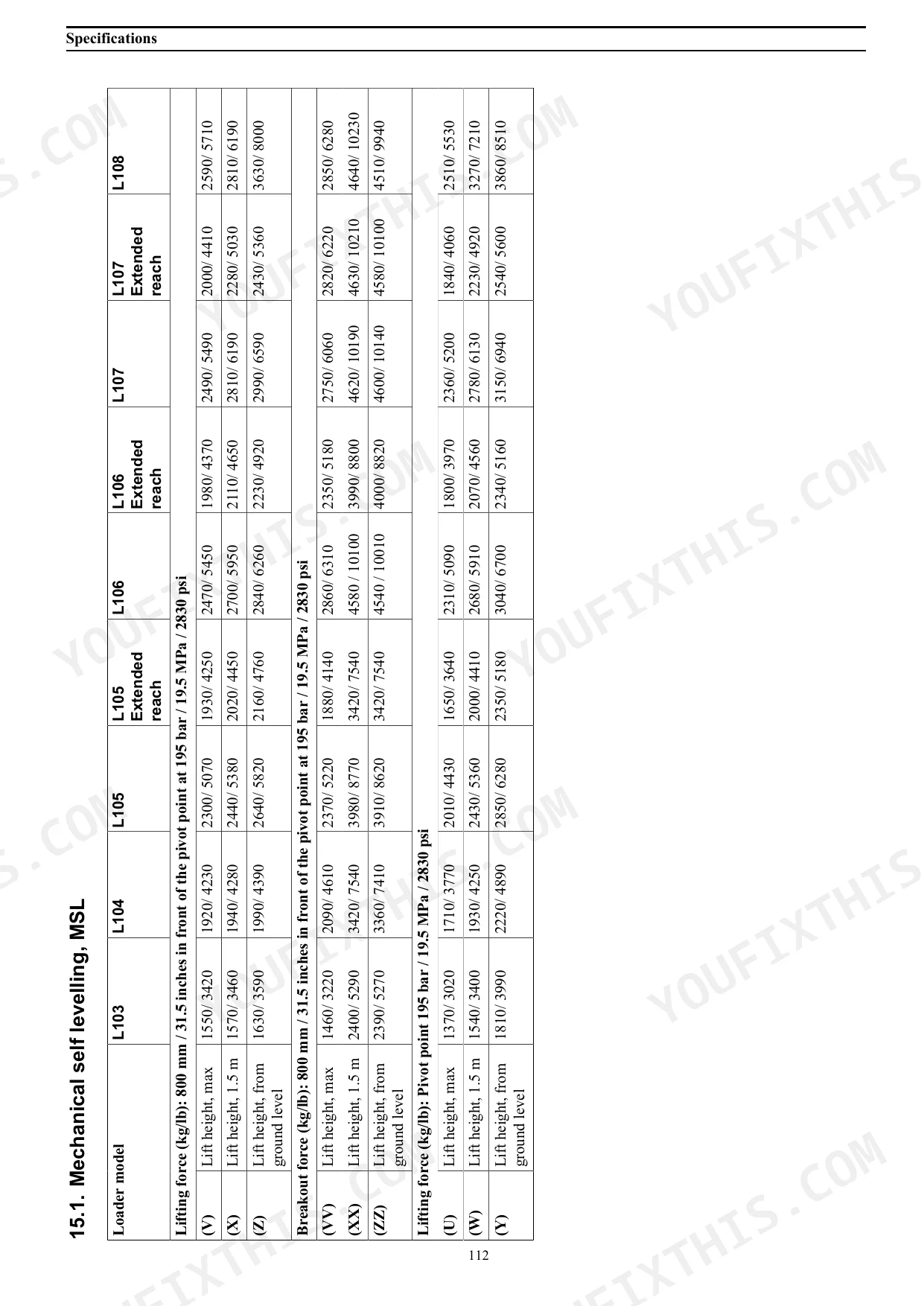
| Specifications | 112-117 | Mechanical Self Levelling, Msl, Non Self Levelling, Nsl |
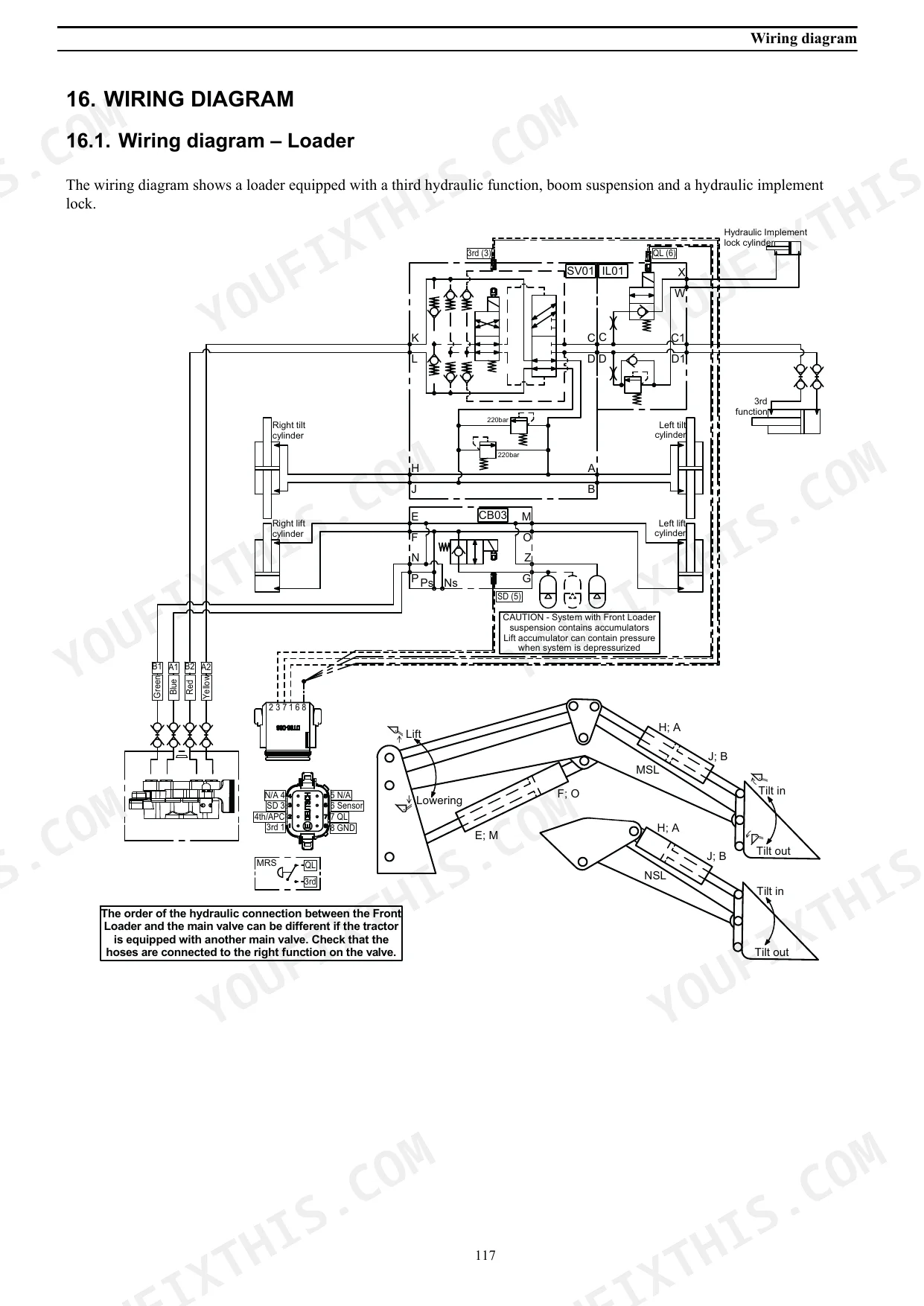
| Wiring Diagram | 118-121 | Wiring Diagram – Loader, Wiring Diagram -Loader with Live3, Wiring Diagram - Loader with All Hydraulic Functions |
Quick Reference Specifications
| Specification | Value | Page |
|---|---|---|
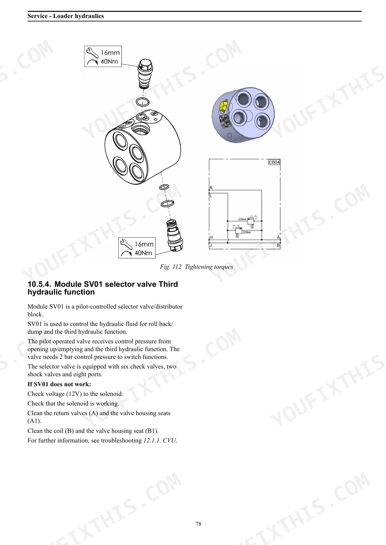
| Module SV01 selector valve fastener torque (16mm) | 40 Nm | p. 110 |
| Module SV02 selector valve fastener torque (4mm) | 12 Nm | p. 110 |
| Cause of erratic hydraulic operation | Air in hydraulic hoses and cylinders | p. 45 |
| Action for erratic hydraulic operation | Run the engine at low speed and make slow movements with the joystick to purge any air from the hydraulic system. | p. 45 |
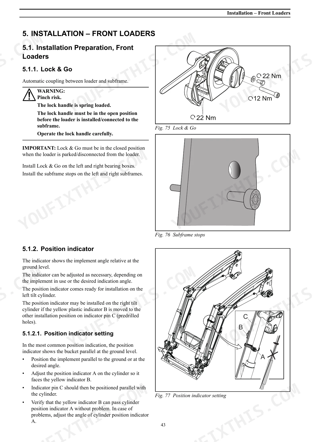
| Lock & Go lock handle torque | 22 Nm | p. 44 |
| Piston tightening torque (cylinders) | 350 Nm | p. 88 |
| Stop screw torque (cylinders) | 3 Nm | p. 89 |
| Max hydraulic pressure | 210 bar / 21 Mpa / 3050 psi | p. 115 |
| Ambient working temperature | -30/+50 C° / -22/+122 °F | p. 115 |
| UNC 1/4" bolt tightening torque (class 8.8) | 11 Nm (8 lb-ft) | p. 110 |
| M24 bolt tightening torque (class 10.9) | 897.5 Nm (662 lb-ft) | p. 110 |
| MSL L103 Max lift height (V) | 1550 kg / 3420 lb | p. 113 |
Case IH L103–L795 Series Common Problems This Manual Covers
Hydraulic response is jerky and erratic, loader movements are unpredictable and hard to control
Run the engine at low speed and make slow, deliberate joystick movements to purge air from the hydraulic system. Air in the hoses and cylinders is the primary cause of erratic operation after installation or hose replacement. Inspect all hose connections per page 71 for loose fittings. If the problem persists after purging, check the troubleshooting table on page 105 for slow or jerky lifting causes.
Manual Section: Service - Loader Hydraulics p. 70Tilt cylinder piston rod bends or seals fail repeatedly after normal bucket work
Inspect the tilt cylinder using the appropriate disassembly procedure: MSL loaders start on page 82, NSL loaders on page 91. Check for bent piston rods before resealing. Replace seals and torque the piston to 350 Nm on reassembly. Also inspect the pins and bushings on the tool carrier (page 65) for wear, since excess play transfers side loads into the cylinder and accelerates seal failure.
Manual Section: Service - Cylinders p. 82Hydraulic hose leaks at connector, fluid dripping under the boom arm during operation
Relieve all hydraulic pressure before touching any fitting. Replace the leaking hose or connector following the procedure on page 71. After reconnecting, run the loader through full lift and tilt cycles at low engine speed and check every connection for seepage. Verify the system holds maximum pressure of 210 bar (3050 psi) without visible leakage before returning the machine to work.
Manual Section: Service - Loader Hydraulics p. 71Boom suspension stops working, ride comfort gone and frame takes hard impacts on rough ground
Inspect the accumulators for damage or pressure loss using the replacement procedure on pages 73-75. Check the troubleshooting table on page 105 under boom suspension not working for valve and electrical causes. Verify the CVU modules are properly connected and that IL01 hydraulic lock valve fasteners are torqued to 12 Nm (4mm) and 40 Nm (16mm). A failed accumulator cannot be recharged in the field; replace the unit.
Manual Section: Service - Loader Hydraulics p. 73Frequently Asked Questions
What are the torque specs for the mounting bolts on the Case IH L103 front loader?
The tightening torques for mounting bolts on the Case IH L103 front loader vary depending on the screw thread and bolt class. For example, a UNC 1/4" class 8.8 bolt requires 11 Nm (8 lb-ft), while an M24 class 10.9 bolt requires 897.5 Nm (662 lb-ft). Refer to Table 13.1.1. on page 110 for a comprehensive list of tightening torques for all subframe hardware and fasteners. p. 110
What is the working height and reach specification for the Case IH L103 front loader?
For the Case IH L103 Mechanical Self Levelling (MSL) loader, the maximum lift height to the pivot point is 3550 mm (139.8 inches), and the reach at maximum excavation depth to the pivot point is 1835 mm (72.2 inches). For the Non-Self Levelling (NSL) L103 loader, the maximum lift height to the pivot point is also 3550 mm (139.8 inches), with a reach at maximum lift height to pivot point of 1530 mm (60.2 inches) and a reach at maximum excavation depth to pivot point of 1835 mm (72.2 inches). p. 113
How do you fix case IH L103-L108 lift cylinder drifts downward under load, bucket slowly drops?
Remove the lift cylinder and inspect seals per the disassembly procedure starting on page 98. Replace the full seal kit if you find cracking, swelling, or flat spots on the piston seals. When reassembling, torque the piston to 350 Nm and the stop screw to 3 Nm. Verify system pressure holds at 210 bar (3050 psi) maximum after reassembly. p. 98
How do you fix loader won't lift bucket at all, arm stays on the ground regardless of joystick input?
Check the troubleshooting table on page 105 for non-functioning lift cylinder causes. Verify hydraulic fluid level first, then check that the control valve spool moves freely. Inspect the CVU module fasteners: SV01 16mm bolts should be at 40 Nm, SV02 4mm bolts at 12 Nm. If pressure still won't build to 210 bar (3050 psi), the pump likely needs inspection through your tractor service channel. p. 105
Is this Service Manual a digital download?
A 121-page Service Manual in searchable PDF format, available the moment you complete checkout. View on computer, tablet, or phone, with no shipping wait.
Is this Case IH L103–L795 Series Service Manual printable?
Yes. The PDF has no DRM restrictions, so print any page or section you need for your shop. Works with any standard printer.
Are there wiring harness diagrams in this Case IH L103–L795 Series manual?
Yes, full electrical schematics are included with wire colors, connector locations, and circuit descriptions.


Reviews
There are no reviews yet.