


Part of the Case IH Repair Manuals.
Got a Case IH LB Square Baler down? This 821-page service manual (OEM #47510985) covers the LB324, 334, 424, and 434, from PTO flywheel and gearbox through pneumatic brakes, hydraulic bale density circuit, and all the way to knotter frame, needles, and grease lubrication. You get full hydraulic schematics for the bale density circuit, complete wiring diagrams with harness routing and connector pinouts for every module, and a fault codes section covering every warning indicator and alarm. Step-by-step procedures run through pickup, rotor, precompression, stuffer, and plunger connecting rod service. Set needle-to-plunger timing clearance to 0-40 mm, then bring knotter gearbox bearing preload to 0.4-0.8 N·m. Factory numbers, not forum guesses. One bad knotter setting buries your whole field run. Bookmarked by system and keyword-searchable; pull it up on your device and get the right spec before you touch the needles.
What's Inside This Case IH LB324–LB434 Manual
| System | Pages | Key Topics |
|---|---|---|
| Introduction | 6-31 | Advice, Foreword, Note to the Owner, Safety Rules, Basic Instructions, Torque, Basic Instructions - Chain Wear Tables - Roller Chains |
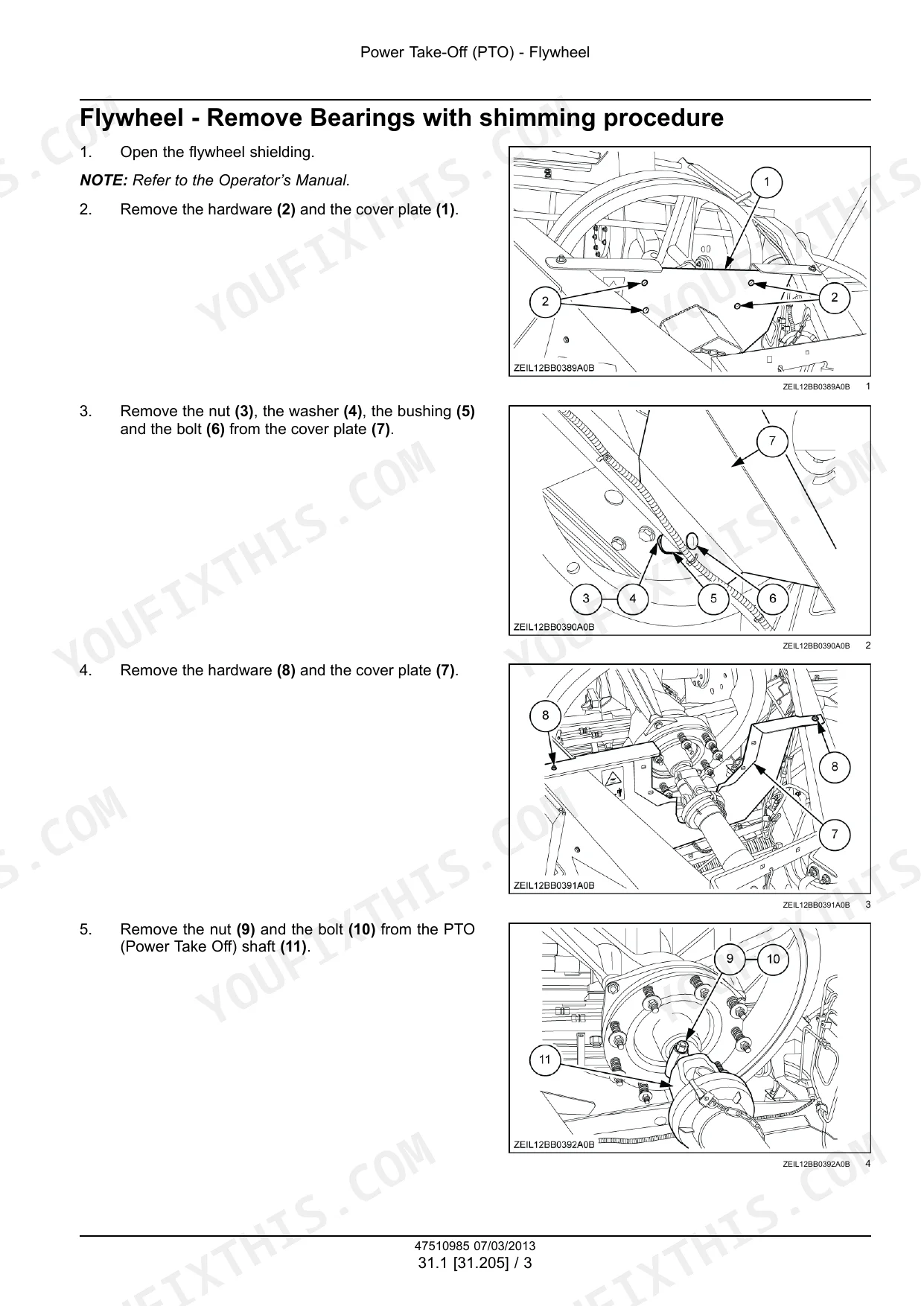
| Power Take-Off (PTO) | 32-119 | Flywheel, Gearbox |
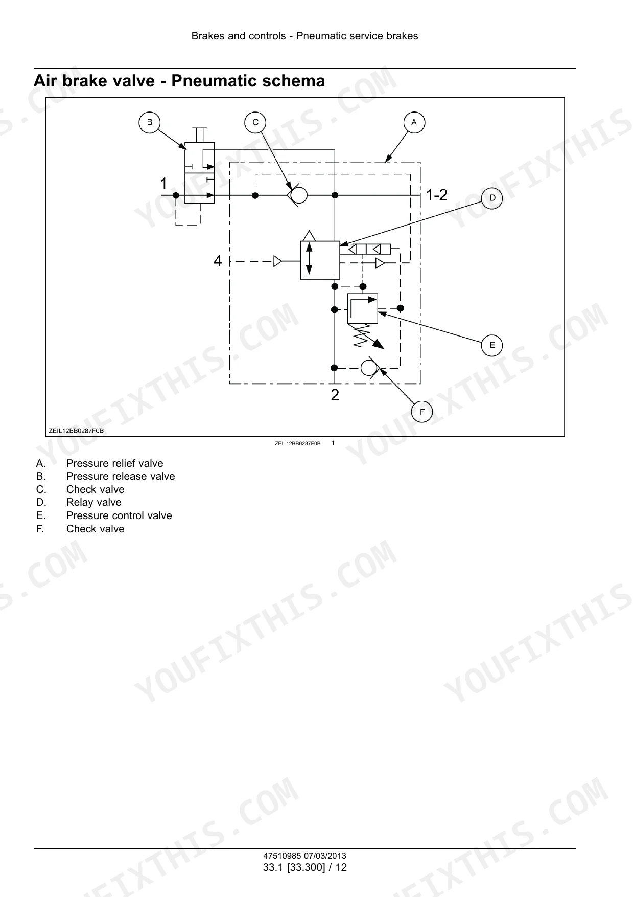
| Brakes and Controls | 120-149 | Pneumatic Service Brakes |
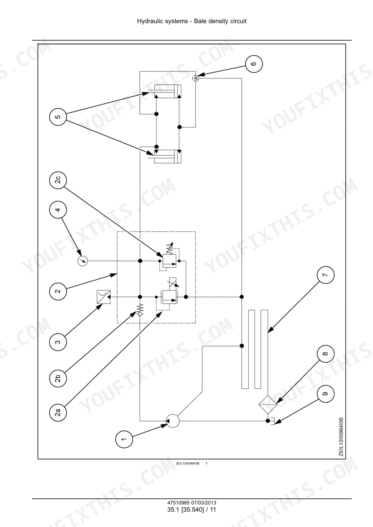
| Hydraulic Systems | 150-177 | Bale Density Circuit |
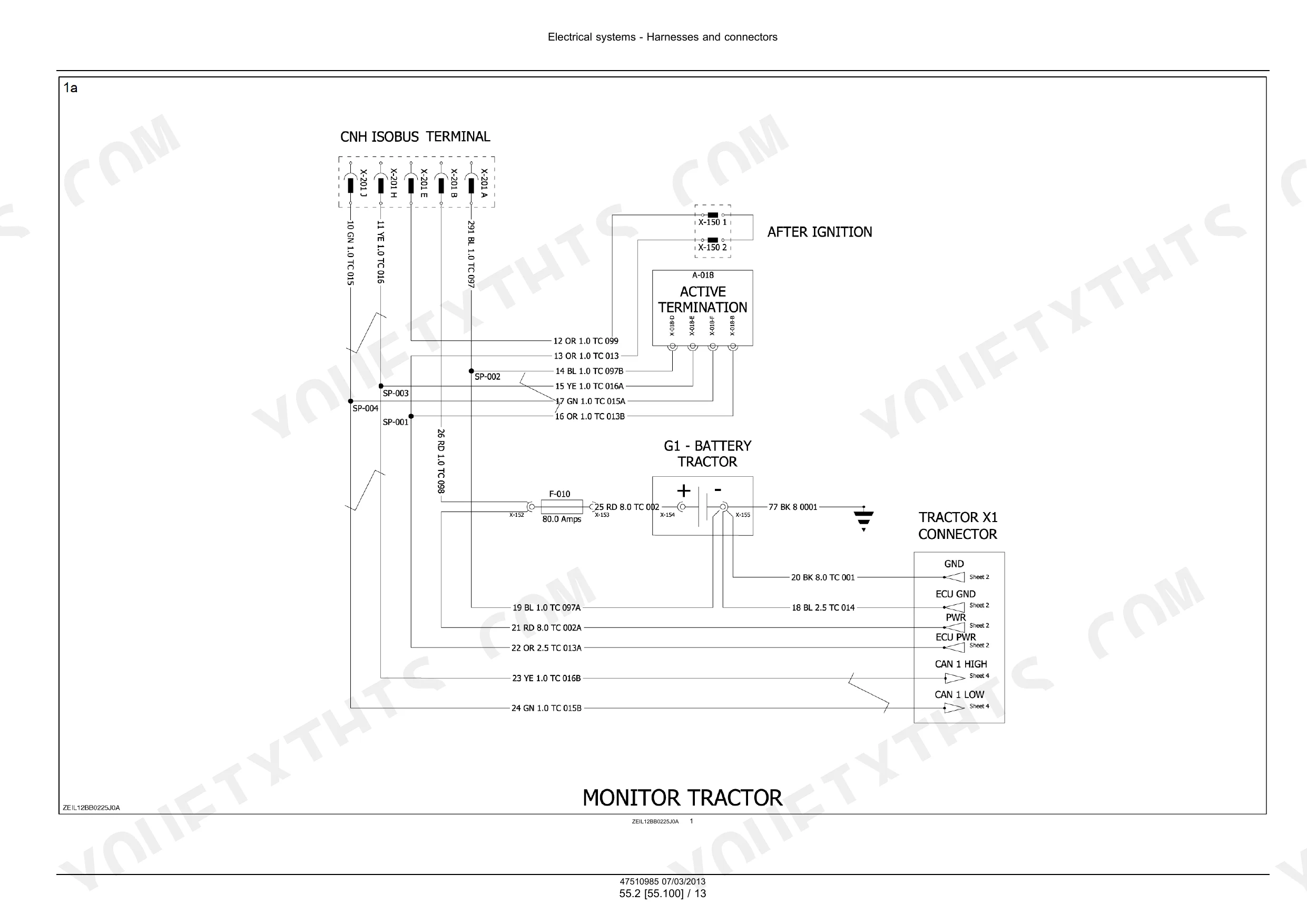
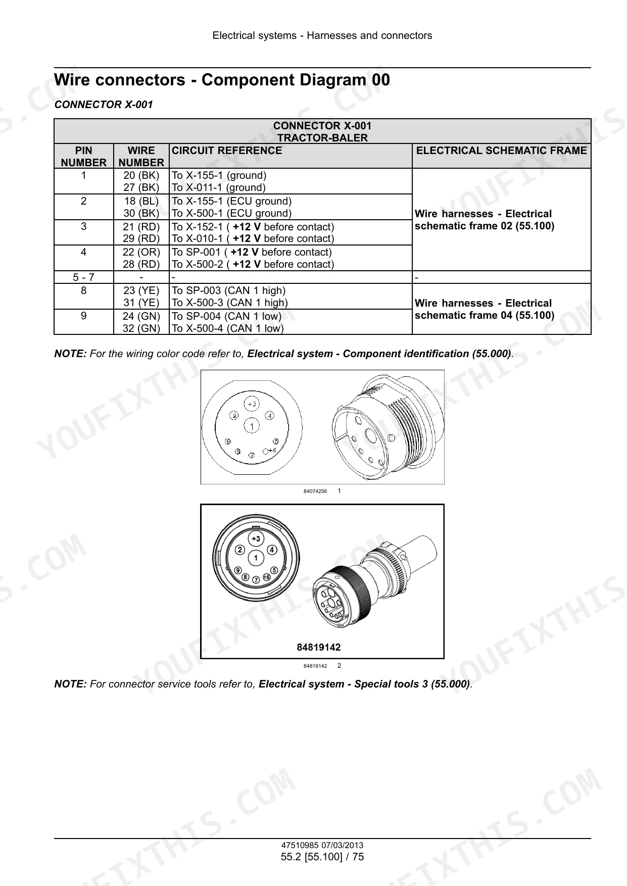
| Electrical Systems | 178-569 | Electrical System, Harnesses and Connectors, Electronic Modules, Pressing/Bale Formation Electrical Control, Warning Indicators, Alarms, And Instruments, Fault Codes |
| Product Feeding | 570-681 | Pickup, Rotor, Precompression, Stuffer |
| Pressing - Bale Formation | 682-695 | Plunger and Connecting Rod |
| Tying/Wrapping/Twisting | 696-751 | Knotter Frame, Knotter Drive System, Knotter Clutch and Brake, Needles |
| Lubrication System | 752-803 | Grease Lubrication System |
| Platform, Cab, Bodywork, and Decals | 804-821 | Machine Shields and Guards |
Quick Reference Specifications
| Specification | Value | Page |
|---|---|---|
| All Models | ||
| Bale length adjustment preload voltage | 5.21 - 5.24 V | p. 539 |
| Needles to plunger timing clearance (distance X between middle of needle top roller and plunger knives) | 0 - 40 mm (0 - 1.6 in) | p. 645 |
| Knotter gearbox bearing preload | 0.4 - 0.8 N·m (0.295 - 0.590 lb ft) | p. 726 |
| Hardware tightening torque (M6, Class 8.8, Plated nut) | 10.1 N·m | p. 18 |
| Hardware tightening torque (M10, Class 10.9, Hardened nut) | 62.5 N·m | p. 18 |
| Flywheel bolt (10) torque | 120 N·m | p. 43 |
| Flywheel preload bolts (S) torque | 97 N·m | p. 44 |
| Gearbox input shaft bearing friction torque | 1.4 - 2.5 N·m | p. 95 |
| Feeder/pickup drive shaft backlash | 0.05 - 0.15 mm | p. 97 |
| Plunger crank drive shaft bearing inner race installation temperature | 80 °C | p. 104 |
| 4-knotter machines | ||
| Gearbox input shaft cover bolts torque | 110 N·m | p. 103 |
| 6-knotter machines | ||
| Gearbox input shaft cover bolts torque | 120 N·m | p. 103 |
Case IH LB324–LB434 Common Problems This Manual Covers
Case IH LB324/LB334/LB424/LB434 square baler plunger roller track showing excessive wear in bale chamber at end of stroke
Inspect the roller track and bale chamber contact zone before each season and every 50 operating hours during heavy use. Remove any debris buildup from the track surface. Check the grease lubrication system: verify pump element rotation, confirm all feed lines deliver grease, and top up the reservoir to its 2 L capacity. Worn bearing surfaces on the roller track should be measured for clearance and replaced before they cause plunger misalignment.
Manual Section: Grease Lubrication SystemPickup floating above windrow during baling, leaving crop on the ground
Check the pickup float spring tension immediately. The pickup must maintain consistent down-pressure contact with the ground contour. Inspect the spring weight kit for missing or collapsed components, and verify the locking clip on the chain adjustment mechanism is fully seated and secured. Adjust wind guard height so it guides crop cleanly into the pickup throat without lifting the unit. Review the Product Feeding section starting at page 570 for float adjustment procedure and spring specifications.
Manual Section: Product Feeding p. 570Knotter mis-ties or broken twine, bales dropping loose from the chamber
Disengage PTO and lock out the machine before inspecting. Check needle-to-plunger timing: the distance X between the middle of the needle top roller and plunger knives must be 0 - 40 mm (0 - 1.6 in) as specified on page 645. Inspect knotter gearbox bearing preload: target 0.4 - 0.8 N·m (page 726) for the gearbox bearing and 0.3 - 0.6 N·m (page 728) for the cover bearing. Replace frayed twine, clean the bill hook and twine disc of crop wraps, and verify the knotter gearbox sensor (B-007) is generating a clean signal per .
Manual Section: Tying/Wrapping/Twisting p. 726Bale density inconsistent or hydraulic pressure fault code on monitor display
Check the bale density circuit overview at page 154. Verify PTO is running at the correct RPM before diagnosing pressure faults. Inspect the oil pressure sensor (B-016) per : measure voltage output and compare against spec; replace if out of range. Check the density valve (Y-002) wiring harness and fuse panel per . Bleed any air from the hydraulic circuit and confirm the bale chamber actuator is reaching operating pressure without excessive foam or overheating.
Manual Section: Hydraulic Systems p. 154Fault code on display, machine stops mid-cycle with no clear mechanical cause
Check fault code reference and record the exact code before clearing. For battery voltage faults, inspect the alternator output and test for blown fuses per . For pickup speed open circuit faults, check the sensor connector and wiring continuity per the wiring harness check: test for short circuits and confirm continuity end-to-end. Inspect the control box for oxidation on connectors and verify cable integrity before replacing any module per .
Manual Section: Electrical SystemsChain drive pulling through pickup throat or jumping under load during operation
Stop the machine immediately if the chain skips or goes slack under load. Disengage PTO and inspect the chain locking clip: confirm it is fully installed and the adjustment is locked. Check chain wear against the roller chain wear tables in the Introduction section starting at page 6. Measure feeder and pickup drive shaft backlash; acceptable range is 0.05 - 0.15 mm (page 97). Replace worn chain links or the full chain if wear limits are exceeded, and re-verify locking hardware before returning to service.
Manual Section: Power Take-Off (PTO) p. 97Frequently Asked Questions
How to reset the baler monitor on Case IH LB434?
The manual indicates that the monitor can be reset to factory settings. To do this, select the “restore factory setting” button on the screen and then confirm the selection by pressing the green V-mark button. p. 463
Torque specs for pickup drive shaft on Case IH LB324/LB334?
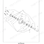
For the pickup assembly on LB324S, LB324P, LB334S, LB334P, LB424S, LB434S models, the lock nut for the bearings (16) and (18) should be tightened to a torque between 70 - 80 N·m (619.6 - 708.1 lb in). This is specified during the installation of the pickup. p. 577
What are error codes for Case IH LB424 XL and how to clear them?
The manual provides a comprehensive list of fault codes (DTCs) and detailed troubleshooting steps to diagnose and resolve the issues causing these codes (pages 469-567). However, it does not describe a specific procedure to "reset" or "clear" error codes from the monitor; resolving the underlying fault is implied to make the code disappear. p. 469
How to reset the safety clutch indicator on LB434 XL?
The manual does not provide a specific procedure to "reset" the safety clutch indicator or warning. It describes how to check the timing of the stuffer mechanism and apply the flywheel brake (page 640), and lists fault codes related to sensors (e.g., "258-Flywheel brake sensor - Line Open" on page 517), but no explicit reset for an indicator. Resolving the underlying mechanical or electrical fault would typically clear such a warning. p. 640
How quickly can I access this manual after buying?
A 821-page Service Manual in searchable PDF format, available the moment you complete checkout. View on computer, tablet, or phone, with no shipping wait.
Can I print this manual?
Yes. The PDF has no DRM restrictions, so print any page or section you need for your shop. Works with any standard printer.
Are there hydraulic schematics in this Case IH LB324 & variants manual?
Yes. The manual includes hydraulic circuit diagrams, system schematics, and component specifications with pressure ratings.


Reviews
There are no reviews yet.