


Part of the Case IH Operator Manuals.
Need the factory rundown for your Case IH Farmall tractor? This 368-page operator manual (OEM #51559261) covers the 85A, 95A, 105A, and 115A models from platform controls to final maintenance intervals. Inside: a full controls and instruments section mapping every switch and gauge on the operator's platform, two dedicated safety chapters covering EU regulation compliance and general safety rules, and a complete working operations guide for rear mechanical control, wheel track adjustment, and tire ballasting. You also get a structured maintenance schedule from the initial 50-hour service through 600-hour oil filter changes, a fault code resolution chapter, and a spec sheet covering engine, cooling, fuel system, and tractor weights. Fill the 4WD fuel tank to 121.0 L; torque rear M18 wheel bolts to 310 N·m. Every hour your tractor sits costs money. PDF opens on any device, bookmarks take you straight to the section you need.
What's Inside This Case IH Farmall 85A/95A/105A/115A Operator Manual
| System | Pages | Key Topics |
|---|---|---|
| General Information | 9-16 | Metric and Imperial Units Abbreviations, To the Owner, Product Identification, Ecology and the Environment |
| Safety Information | 17-80 | Safety Precautions, Safety Aspects in Accordance with Regulation (Eu) 1322/2014 - Annex Xxii and Sub, Safety Rules, Safety Rules - General Information, Safety Rules – Maintenance |
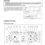
| Controls and Instruments | 81-148 | Access to Operator's Platform, Operator's Seat, Instructional Seat, Forward Controls, Left-Hand Side Controls, Right-Hand Side Controls, Analogue/ Digital Instrument Cluster |
| Operating Instructions | 149-156 | Starting the Unit, Stopping the Unit |
| Transport Operations | 157-158 | Preparing for Road Transport, Recovery Transport |
| Working Operations | 159-218 | Rear Mechanical Control, Wheel Track Adjustment, Wheels, Ballasting and Tires |
| Maintenance | 219-300 | Maintenance Planning, As Required Maintenance, At Warning Message Display, Every 10 Hours or Each Day, Initial 50 Hours, Every 50 Hours, Every 100 Hours |
| Troubleshooting | 301-316 | Fault Code Resolution, Alarm(s) |
| Specifications | 317-338 | Introduction, Consumables, General Dimensions, Weights, Tractor Weights, Engine Specifications, Engine Cooling System, Fuel System |
| Accessories | 339-358 | Rotating Beacon, Quick Hitch, Swinging Drawbars, Hydraulically Operated Towing Hitch, Trailer Brake Hydraulic Control - Static Description |
| Forms and Declarations | 359-368 | Service Record 1st 50 Hour, Owner Copy, Dealer’s Copy |
Quick Reference Specifications
| Specification | Value | Page |
|---|---|---|
| All 4WD models | ||
| Steering pump pressure relief valve calibration | 170 bar (2465 Psi, 173.352 kg/cm²) | p. 333 |
| 4WD models | ||
| Fuel Tank Capacity (4WD) | 121.0 L | p. 222 |
| All Models | ||
| Engine Oil Filter Change Interval | 600 hours | p. 231 |
| Wheel Bolt Torque (Rear - M18) | 310 N·m | p. 281 |
| Air Conditioning Refrigerant Quantity | 1.6 kg | p. 99 |
| Max Pump Pressure (High Pressure Circuit) | 190.0 bar | p. 329 |
| Engine Rated Speed | 2300 RPM | p. 323 |
| Alternator Output | 120 A | p. 337 |
| Battery Capacity | 100 A·h | p. 337 |
| Max Vertical Load on Drawbar (pin 1) | 850 kg | p. 217 |
| with cab models | ||
| Clutch Pedal Stroke (with cab) | 145.0 mm | p. 239 |
Case IH Farmall 85A/95A/105A/115A Common Problems This Manual Covers
Case IH Farmall warning light appears on instrument cluster during or after startup
Check the Display Warnings and Error Codes section starting on page 308 to identify the specific alarm. Note the fault code displayed and cross-reference the error code identification chart. Inspect fluid levels at the sight glasses before clearing any code. If the warning repeats after clearing, do not ignore it — return to the fault code table and follow the listed corrective action for that specific code.
Manual Section: Display Warnings and Error Codes p. 308Engine overheating warning activates during field operation on hot days
Stop the tractor and let it idle at low RPM. Check coolant level in the recovery reservoir — it should be between MIN and MAX marks. Inspect the radiator screen for chaff or debris blockage and clean by hand or with compressed air. Verify the engine cooling fan is turning freely. Review the engine overheating procedure in the Engine Troubleshooting table on page 301 before returning to work.
Manual Section: Troubleshooting p. 301Steering feels heavy or makes a whining noise at mid-range engine speeds
Check hydraulic fluid level first — low fluid is the most common cause of steering whine. Inspect hose connections at the steering circuit for weeping or air ingestion as shown in the Hydraulic System Troubleshooting guide on page 304. On 4WD models, the steering pump pressure relief is set to 170 bar (2465 PSI); if noise persists with correct fluid level, have the circuit pressure verified by a dealer before operating further.
Manual Section: Hydraulic System Troubleshooting p. 304MFWD (mechanical front wheel drive) disengages unexpectedly or fails to engage
Verify the MFWD switch on the operator's platform is fully actuated and not sticking in the intermediate position. Check the switch and connector for corrosion or moisture intrusion. Review the Electrical System Troubleshooting section on page 303 for starter and relay circuit checks that apply to MFWD relay faults. If the switch clicks but the front axle does not respond, have the relay tested before field use.
Manual Section: Electrical System Troubleshooting p. 303A/C system blows warm air after sitting over winter or during first summer use
Check that the A/C compressor engages when the system is switched on — listen for the clutch click. Inspect the cabin air filter for blockage per the Maintenance schedule on page 219. The system holds 1.6 kg of refrigerant (page 99); low charge is the most common cause of warm air. If the compressor engages but cooling is poor, have refrigerant level checked with manifold gauges by a qualified technician before adding refrigerant.
Manual Section: Maintenance p. 99Clutch pedal feels soft or has excessive travel making gear changes difficult
Check that the clutch pedal free play is within spec — on cab-equipped models the total stroke is 145.0 mm (page 239). Adjust the linkage at the pedal stop per the maintenance procedure and recheck pedal feel. If travel remains excessive after adjustment, inspect for hydraulic fluid weeping at the clutch master cylinder reservoir. Refer to the Brakes Troubleshooting section on page 306 for soft-pedal diagnostics that share the same hydraulic circuit inspection steps.
Manual Section: Troubleshooting p. 239Frequently Asked Questions
What are the recommended service intervals?
The manual provides a comprehensive maintenance chart detailing service intervals such as "Every 10 hours or each day" for engine oil level and battery checks, "Initial 50 hours" for tightening bolts and checking various components, "Every 50 hours" for greasing points, "Every 100 hours" for air-conditioning condenser cleaning, "Every 300 hours" for hydraulic circuit oil filter replacement, "Every 600 hours" for engine oil and fuel filter changes, "Every 1200 hours or annually" for air filter replacement, "Every 1200 hours or two years" for front axle oil replacement, and "Every 3600 hours" for engine coolant fluid change. p. 230
What fluids and capacities does this machine require?
The machine requires specific fluids and capacities, including 14 L (3.7 US gal) of CASE IH AKCELA ACTIFULL™ OT EXTENDED LIFE COOLANT for cooling system without cab, 8.5 L (2.25 US gal) of CASE IH AKCELA UNITEK NO. 1™ SBL CJ-4 SAE 10W-40 engine oil, 0.4 L (0.11 US gal) of CASE IH AKCELA LHM FLUID NH 610 A for the brake control circuit, and 46 L (12.15 US gal) of CASE IH AKCELA NEXPLORE™ FLUID NH 410B for rear transmission. p. 229
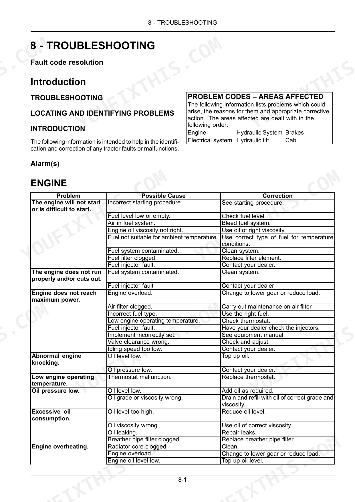
How to troubleshoot engine won't start?
If the engine will not start or is difficult to start, possible causes include an incorrect starting procedure, low or empty fuel level, air in the fuel system, incorrect engine oil viscosity, unsuitable fuel for ambient temperature, contaminated fuel system, or a clogged fuel filter. The corresponding corrections are to check the starting procedure, check fuel level, bleed the fuel system, use the correct oil viscosity, use the right fuel type, clean the fuel system, or replace the fuel filter element. p. 301
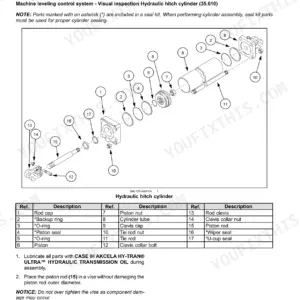
What are the hydraulic system specifications?
The hydraulic system uses a tandem gear pump. For Synchro Shuttle™ models, the high-pressure circuit pump capacity is 19.00 cm³ (1.16 in³) with a flow of 47.50 l/min (12.55 US gpm) and a maximum pressure of 190.0 bar (2755.0 psi). The low-pressure circuit has a pump capacity of 11.00 cm³ (0.67 in³) with a flow of 27.50 l/min (7.26 US gpm) and a maximum pressure of 170.0 bar (2465.0 psi). p. 329
What torque specifications are listed?
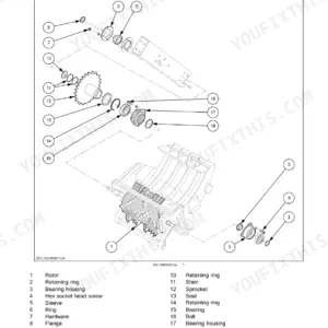
The manual lists several torque specifications: front wheel disc to hub nuts require 220 N·m (162.3 lb ft), rear wheel disc to hub nuts require 310 N·m (228.6 lb ft), and disc to rim nuts require 250.0 N·m (184.4 lb ft). For front wheel track adjustment, retaining bolts and nuts are 220 N·m (22.5 kgm), and steering rod locking screws are 39 N·m (4 kgm). The exhaust pipe mounting torque is 40 N·m (29.7 ftlbs). p. 281
How will I receive this Case IH Farmall 85A, 95A, 105A, 115A Operator Manual?
You get a 368-page searchable PDF that downloads instantly after checkout. Open it on your laptop, tablet, or phone, and bring it right to the shop floor.
Can I print this manual?
The PDF is DRM-free. Print whatever sections you need to take out to the shop. Standard letter or A4 paper works.


Reviews
There are no reviews yet.