


This International Service Manual is a 108 page factory guide, published in 1973 (part number 1091624R2), for the Neuss built Basic Diesel Engines. It covers the naturally aspirated D-155, D-179, D-206, D-239, D-246, D-268, D-310, and D-358, plus the turbocharged DT-239, DT-358, and DT-402.Written in English with a full text layer, it documents the complete engine from service diagnosis and specifications through the valve gear, camshaft, cylinder head, crankshaft, pistons, sleeves, and connecting rods. Fuel system coverage includes the VA and VE injection pumps, the nozzle holders, and timing.Cooling, oil pump, water pump, and thermostat service are included, along with a full engine testing section, so a rebuilder or mechanic can work through an overhaul or a targeted repair on any engine in the family.
What's Inside This International D-155 & variants Manual
| System | Pages | Key Topics |
|---|---|---|
| Introduction | 4 | - |
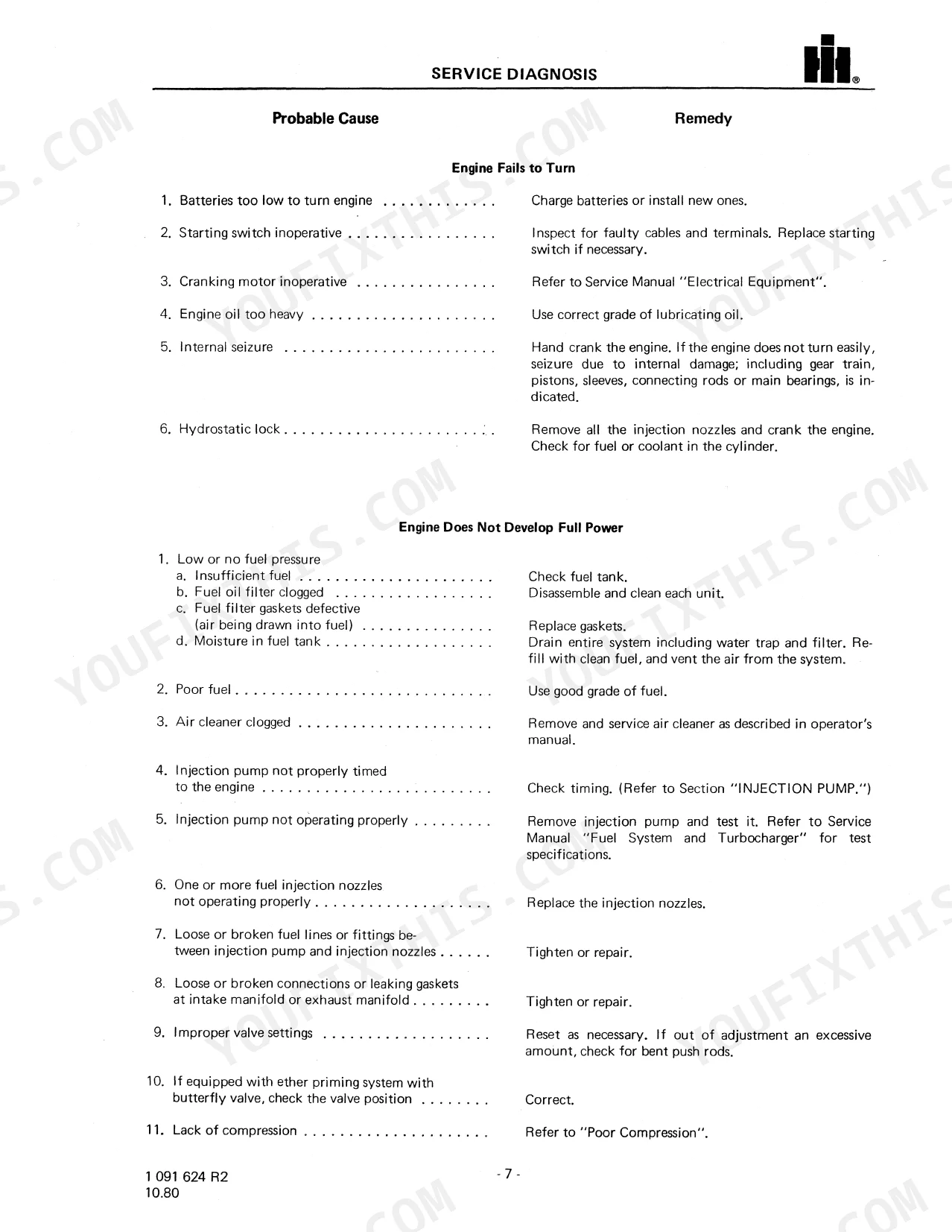
| Service Diagnosis | 9-14 | Work Safely - Follow Those Rules, Gaskets and Seals, Service Tools, Service Parts, Serial Numbers, Priming Lubricating System, Engine Run-In Schedule, Start |
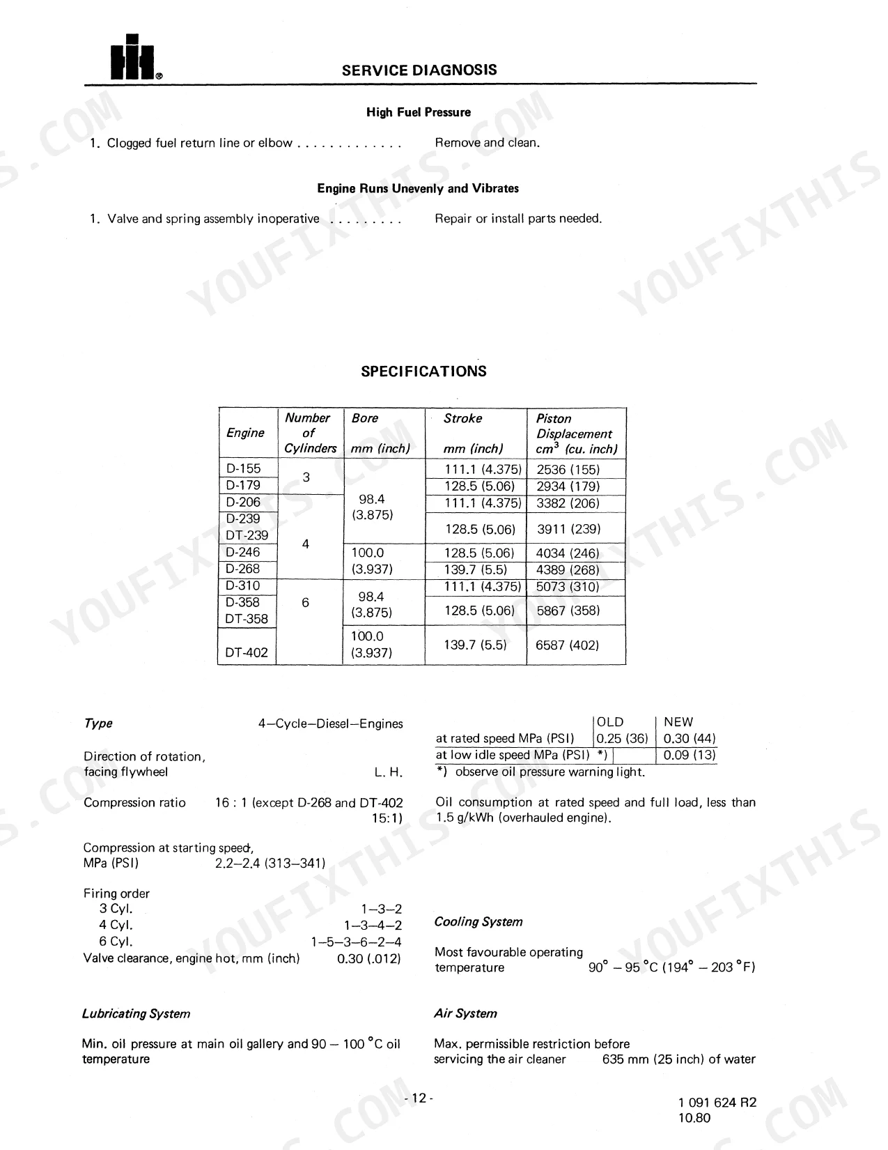
| Specifications | 15-17 | Valves Sticking, Piston and Cylinder Sleeve Wear, Improper Fuel Pressure, Low Engine RPM, Low Fuel Pressure, High Fuel Pressure, Engine Runs Unevenly and Vibrates, Type |
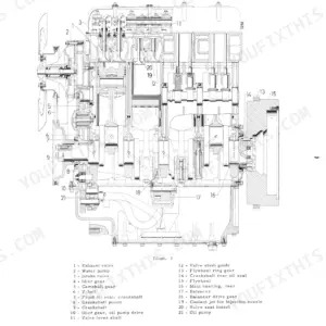
| Longitudinal and Cross Section | 18-19 | Longitudinal Section of Engine, Illust. 3 Typical Dt-358 Engine, Cross Section of Engine, Illust. 4 Typical Dt-358 Engine, Valve Lever Springs, Removal and Disassembly, Cleaning |
| Valve Lever Assy | 20-22 | Valve Lever, Shaft, Valve Lever Springs, Removal, Disassembly, Reassembly |
| Camshaft and Idler Gear | 23-28 | General, Removal and Disassembly, Cleaning, Inspection and Repair, Procedure for Line Boring Camshaft Bushings, Camshaft Gear, Thrust Plate and Idler Gear |
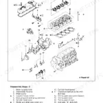
| Cylinder Head Valves and Valve Guides | 29-40 | Idler Gear Carrier and Needle Bearings, Reassembly and Installation, General, Oversize Valve Seat Insert Counterbore Chart, Valve Timing, Valve Dimensional Chart |
| Manifolds | 41 | Intake Manifold, Exhaust Manifold, Turbocharger Installation, Air Hose, Fuel Lines, Gaskets |
| Fan - V-Belts | 42 | General, Cleaning, Inspection and Repair, Installation |
| Crankshaft Pulley and Vibration Damper | 43-44 | General, Removal and Disassembly, Cleaning, Inspection and Repair, Installation, Removal |
| Crankcase Front Cover and Plate | 45-46 | Reassembly and Installation, General, Removal and Disassembly |
| Crankcase | 47-50 | Cleaning, Inspection and Repair, Reassembly and Installation, Installation of the Front Oil Seal, Crankcase Front Cover in Place, General, Removal and Disassembly |
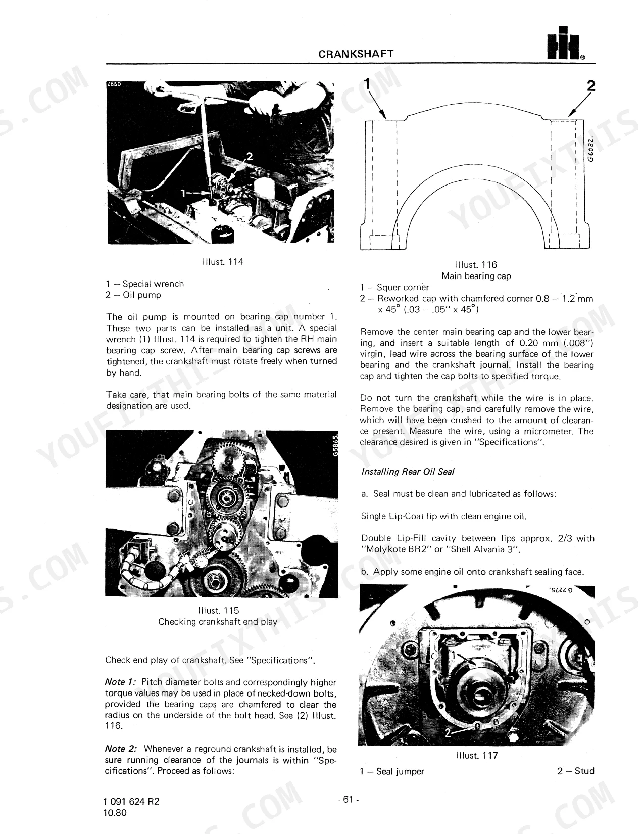
| Crankshaft | 51-64 | Grinding the Cutter, General, Hardening Processes, Straightening, Crankshaft Rear End Sealing Flange, Re-Hardening Processes for Nitrided Crankshafts |
| Pistons Cylinder Sleeves - Connecting Rods | 65-73 | General, Groove Diameter, Piston Versions, Piston Ring Gap, Piston Pin Dia, Removal and Disassembly, Checking Cylinder Sleeve Wear, Cleaning |
| Balancer (4-Cyl. Only) | 74-78 | General, Removal and Disassembly, Repair, Reassembly |
| Flywheel | 79-81 | Installation, Removal and Disassembly, Cleaning, Inspection and Repair |
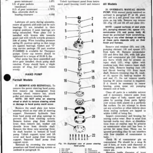
| Oil Pump | 84-87 | Body Gears, Relief Valve, Idler Gear, Drive Gear, Crankshaft Pinion, Roller Bearing |
| Water Pump | 88-90 | Idler Gear Fastening with Self-Locking Nut, Idler Gear Shaft Replacement, General, Removal and Disassembly, Cleaning, Inspection and Repair, Reassembly |
| Thermostat and Coolant Manifold | 91-92 | Thermostat, Removal and Disassembly, Inspection and Repair |
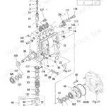
| Injection Pump Ep/Va-Ve | 93-97 | Removal and Disassembly, Repair, Installation, General, A. Checking Static Timing, B. Removal, C. Installing and Timing the Pump to the Engine |
| Injection Nozzle Holder | 98 | Fuel Feed Pump, Installation, A. Flange Mounted Holder, B. Crab Mounted Holder |
| Timing Gear Train | 99-100 | Adjustment, Illust. 212, Illust. 212 Shows the Gear Train of a 6-Cyl.-Engine with Piston Number One on Compression TDC, Timing Chart for Injection Pump Gear Illust. 212 |
| Valve Lash Adjustment | 101-102 | Valve Lever, Feeler Gauge, Adjusting Screw, Lock Nut, Adjusting Valve Lash |
| Engine Testing | 103-108 | Valve Timing, Compression, Lubricating Oil Pressure, Air Cleaner Restriction, Boost Pressure, Crankcase Pressure Orificed Restrictor |
Quick Reference Specifications
| Specification | Value | Page |
|---|---|---|
| Cylinder-head cap screws with collar torque | 14+15 daNm (101+109 Lbf-ft) | p. 17 |
| Valve cover screws (sheet metal) torque | 0.5+0.7 daNm (3.6+5 Lbf-ft) | p. 17 |
| Valve cover screws (gray iron) torque | 1.5+1.7 daNm (11+12.3 Lbf-ft) | p. 17 |
| Nozzle holder stud nuts (flange mounted) torque | 1.3+1.8 daNm (9.4+13 Lbf-ft) | p. 17 |
| Nozzle union nut (nozzle holder) torque | 6-8 daNm (44-58 Lbf-ft) | p. 17 |
| Injection pump flange nut torque | 2.2+2.5 daNm (16+18 Lbf-ft) | p. 17 |
| Injection pump gear bolt (3 radial lines) torque | 2.2+2.5 daNm (16+18 Lbf-ft) | p. 17 |
| Fuel feed pump replacement | Install a new feed pump if the diaphragm is damaged or the operating mechanism is defective. | p. 97 |
| Oil pump idler gear end play | 0.0 - 0.05 mm (0.0 - .002 in.) | p. 84 |
| Oil pump drive gear end play | 0.10 mm (.004 in.) | p. 84 |
| Water pump bearing assembly replacement | Replace bearing assembly (1) Illust. 186 with a new one, if pump has been running rough and/or noisy. | p. 88 |
| Thermostat (5) opening temperature | 78 - 82°C (172 - 180 °F) | p. 91 |
International D-155 & variants Common Problems This Manual Covers
Hard starting or no-start
Weak compression, air in the fuel system, or poor fuel delivery leave these diesels hard to start, especially cold. The service diagnosis section works through the engine that turns but will not start.
Manual Section: Service Diagnosis p. 9Blue smoke and blow-by
Worn rings, cylinder sleeves, or valve guides raise oil consumption and blow-by on higher hour engines. This section covers piston, ring, and sleeve wear limits and replacement.
Manual Section: Pistons Cylinder Sleeves - Connecting Rods p. 65Overheating and coolant loss
A stuck thermostat, a weak water pump, or scaled passages cause repeated overheating and boil-over. The thermostat section gives opening temperatures and full stroke figures.
Manual Section: Thermostat and Coolant Manifold p. 91Low power under load
Injection pump wear, calibration drift, or a fuel restriction rob the engine of power under load. This section covers pump timing, removal, and installation for the VA and VE pumps.
Manual Section: Injection Pump Ep/Va-Ve p. 93Low oil pressure or bearing knock
A worn oil pump, a clogged pickup, or bearing wear shows up as low oil pressure or a knock. The oil pump section covers gear end play, backlash, and relief valve checks.
Manual Section: Oil Pump p. 84Misfire and rough idle
A fouled or worn injector nozzle causes misfire, white smoke, and a rough idle. The nozzle holder section covers the flange and crab mounted holders and the fuel feed pump.
Manual Section: Injection Nozzle Holder p. 98Frequently Asked Questions
Which engines does this manual cover?
It covers the International Basic Diesel Engines built at Neuss: the D-155, D-179, D-206, D-239, D-246, D-268, D-310, and D-358, plus the turbocharged DT-239, DT-358, and DT-402.
Does it list torque specifications?
Yes. The specifications section includes the special nut and bolt torque data, covering cylinder head, injection pump, and nozzle holder values. p. 15
Does it cover valve lash adjustment?
Yes. A dedicated valve lash adjustment section shows how to set clearance with a feeler gauge, the adjusting screw, and the lock nut. p. 101
Does it cover injection pump timing?
Yes. The injection pump section covers checking static timing and installing and timing the VA and VE pumps to the engine. p. 93
What format is this manual in?
A 108-page Service Manual in searchable PDF format, available the moment you complete checkout. View on computer, tablet, or phone, with no shipping wait.
Can I print this manual?
No restrictions at all. Print individual pages, full chapters, or the entire manual. The PDF is completely unlocked.
Reviews
There are no reviews yet.