
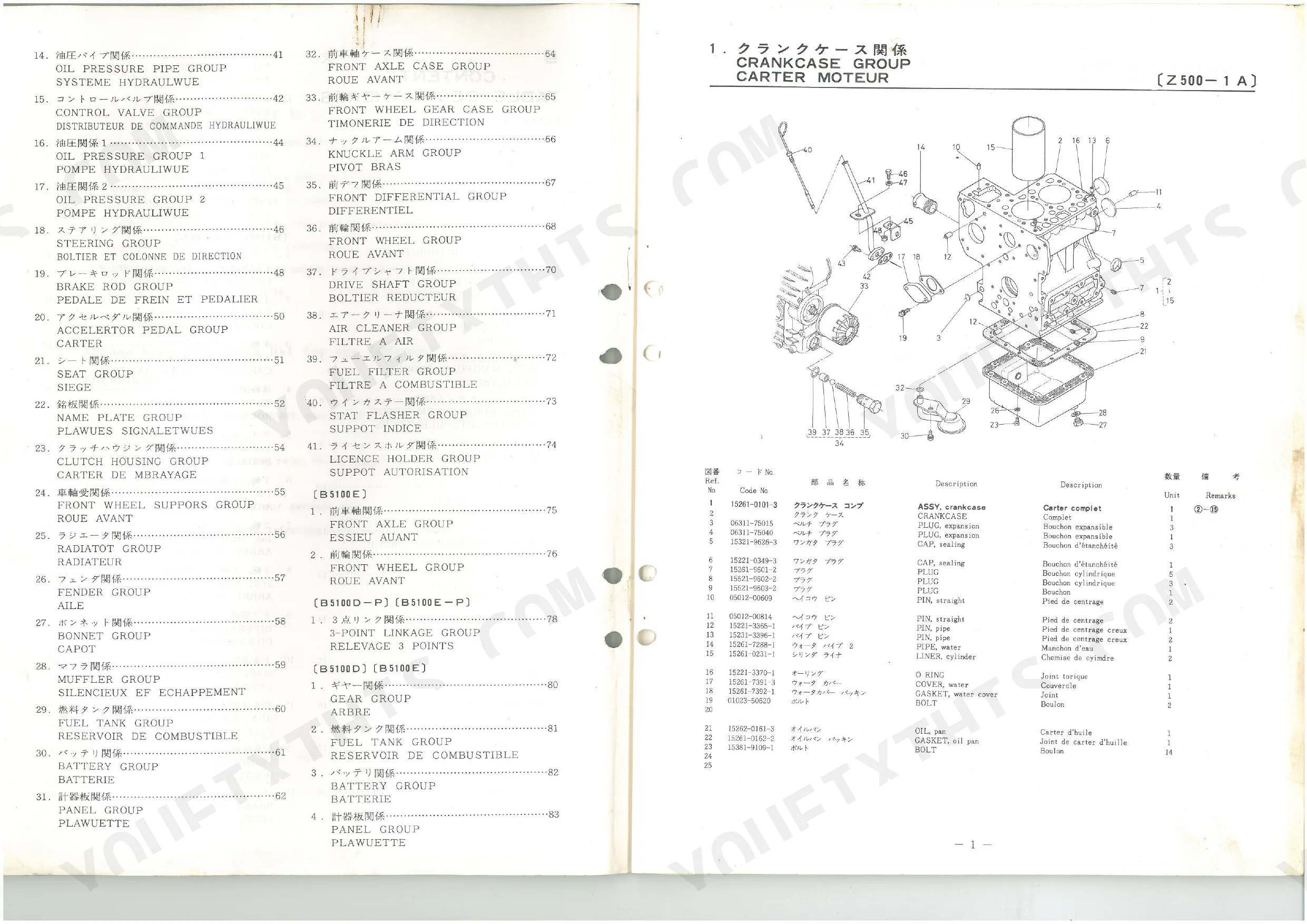
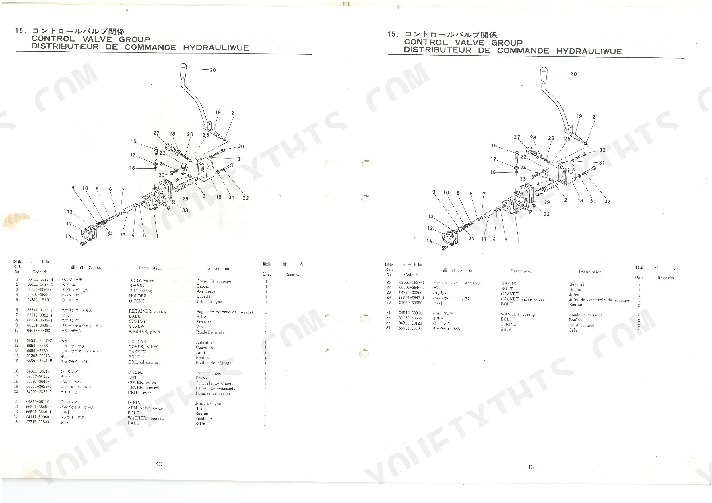
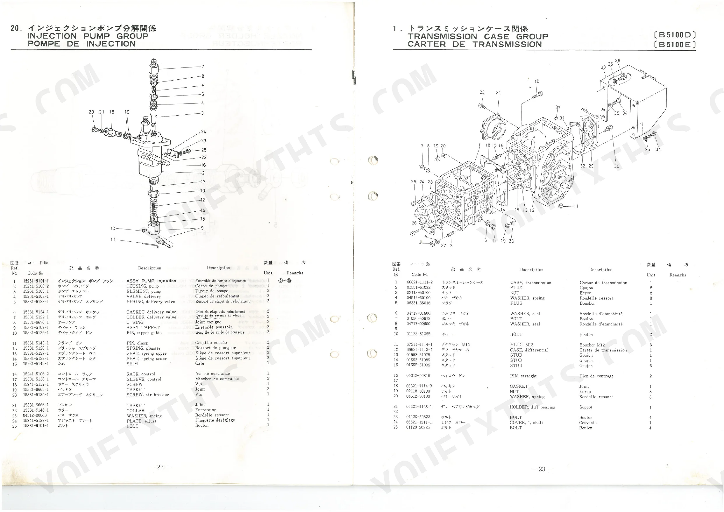
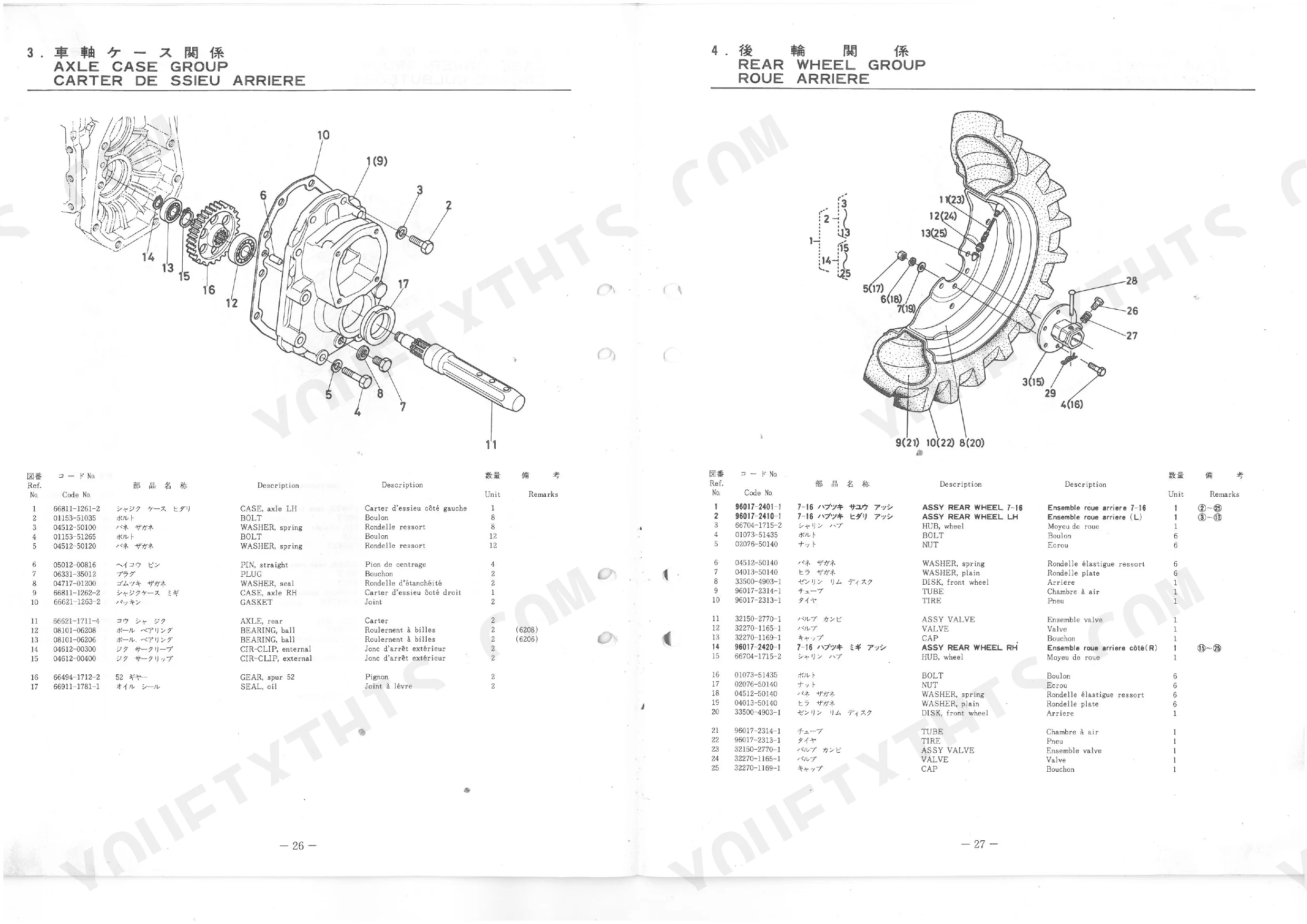
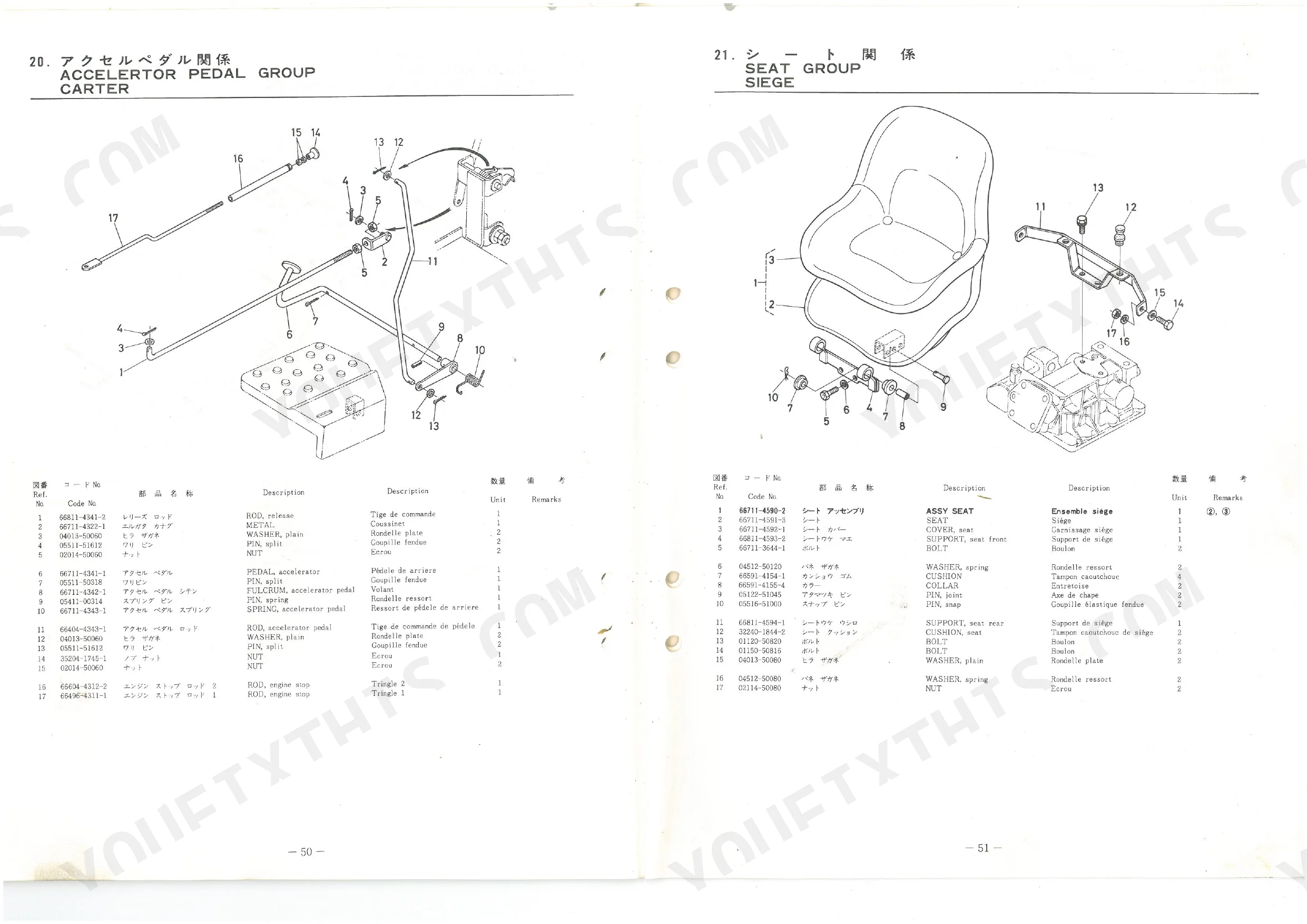
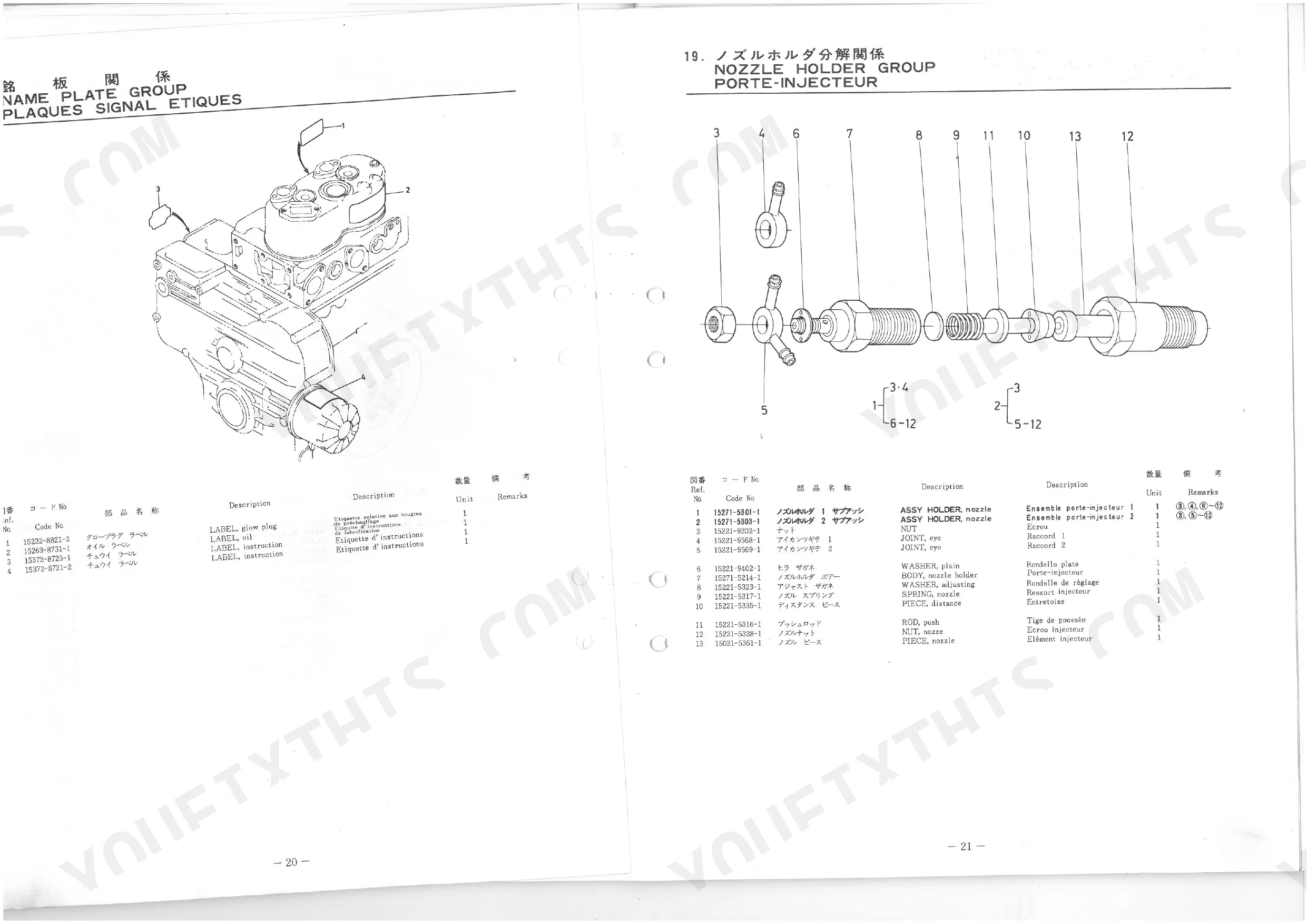
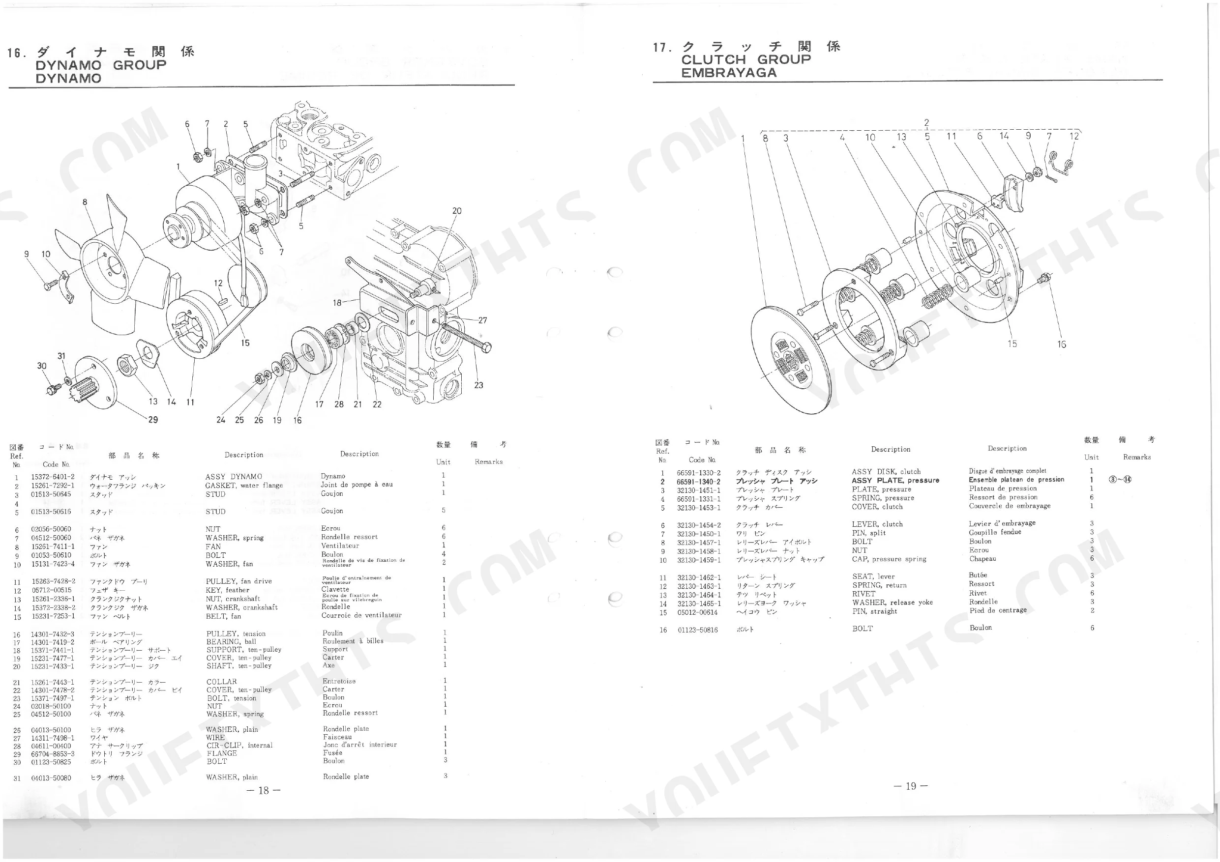
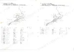
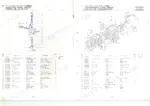
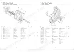
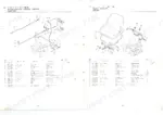
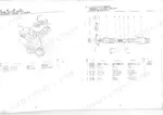
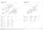
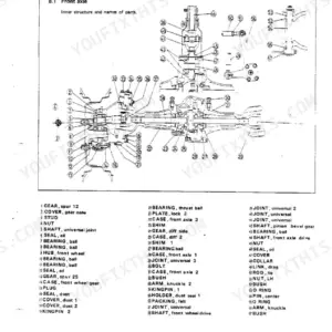
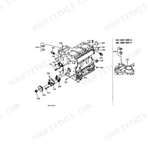
Every part number in this Kubota B5100D, B5100E Parts Catalog (OEM #66496-6292-5) is here to get you ordering before you walk to the counter. The 46 pages run from exploded views (14 of them cover engine components alone) through drivetrain, chassis, hydraulic, and electrical assemblies, each diagram labeled and matched to a parts list table. hydraulic parts diagrams map the full oil pressure circuit, control valve group, and steering system, so you can pin down the exact component you're pulling. Numbered reference tables sit beside every diagram: crankcase, cylinder head, camshaft, piston and crankshaft, injection pump, transmission shafts, differential, brakes, front axle, 3-point linkage, and more. Your B5100 runs 2 pistons, 2 inlet valves, 2 exhaust valves, and 8 cylinder head bolts, each tied to a part number. No more digging through dealer microfiche for numbers that may be discontinued. Bookmarked throughout; search a part name and land on its diagram.
What's Inside This Kubota B5100D, B5100E Parts Manual
| System | Pages |
|---|---|
| Crankcase Group | 3-3 |
| Cylinder Head Group | 4-4 |
| Gear Case Group | 5-5 |
| Breather Group | 6-6 |
| Valve, Rocker Arm Group | 7-7 |
| Camshaft Group | 8-8 |
| Piston, Crankshaft Group | 9-9 |
| Nozzle Holder Group | 10-10 |
| Speed Control Plate Group | 11-11 |
| Dynamo Group | 12-12 |
| Name Plate Group | 13-13 |
| Injection Pump Group Disassembly | 14-14 |
| Case Cover Group | 15-15 |
| Axle Case Group | 16-16 |
| Clutch Rod Group | 17-17 |
| 1st Shaft, 4th Shaft Group | 18-18 |
| 2nd Shaft, Reverse Shaft Group | 19-19 |
| 3rd, 5th, PTO Shaft Group | 20-20 |
| Main Speed Change Group | 21-21 |
| Auxiliary Speed Change Group | 22-22 |
| Brake Group | 23-23 |
| Control Valve Group | 24-24 |
| Oil Pressure Group 1 | 25-25 |
| Steering Group | 26-26 |
| Brake Rod Group | 27-27 |
| Accelerator Pedal Group | 28-29 |
| Clutch Housing Group | 30-30 |
| Radiator Group | 31-31 |
| Bonnet Group | 32-32 |
| Fuel Tank Group | 33-33 |
| Panel Group | 34-39 |
| Front Axle Group | 40-40 |
| Front Wheel Group | 41-41 |
| Point Linkage Group | 42-42 |
| Gear Group | 43-43 |
| Battery Group | 44-46 |
Every system also includes a parts diagram and a parts list table.
Quick Reference Specifications
| Specification | Value | Page |
|---|---|---|
| Cylinder Head Bolt Quantity | 8 units | p. 4 |
| Inlet Valve Quantity | 2 units | p. 7 |
| Exhaust Valve Quantity | 2 units | p. 7 |
| Valve Spring Quantity | 4 units | p. 7 |
| Piston Quantity | 2 units | p. 9 |
| Connecting Rod Bolt Quantity | 4 units | p. 9 |
| Crankpin Metal Quantity | 4 units | p. 9 |
| Clutch Pressure Spring Quantity | 6 units | p. 12 |
| Axle Case Spur Gear Teeth | 52 teeth | p. 16 |
| 1st Shaft Gear Teeth | 29 teeth | p. 18 |
| 2nd Shaft Gear Teeth | 34 teeth | p. 19 |
| Differential Spiral Bevel Gear Teeth | 37 teeth | p. 21 |
Kubota B5100D, B5100E Common Problems This Manual Covers
Engine loses power, compression reads low, and the breather pushes excessive blowby p. 4
Check the exploded view on page 4 to pull the right head gasket and hardware numbers, then order 8 cylinder head bolts as the parts list specifies. Cross-reference the casting numbers so the replacements match.
Manual Section: Cylinder Head GroupRear wheel drive locks up and makes a loud grinding noise from the axle housing p. 16
Review the chassis diagram on page 16 to locate the axle case spur gear, and confirm the replacement carries 52 teeth. Match the index part number to order the right bearings and seals for reassembly.
Manual Section: Axle Case GroupTractor hesitates under heavy load and emits a burning smell from the bell housing area p. 12
Inspect the clutch diagram on page 12 for the friction disc and throwout bearing numbers, then buy 6 clutch pressure springs to finish the assembly. Confirm the part numbers against your chassis serial number.
Manual Section: Clutch System Component RepairEngine runs rough with loud tapping noises coming directly from the top cover p. 7
Trace the exploded view on page 7 to the correct rocker arm and pushrod numbers, then order 4 valve springs to wrap up the cylinder head service. Check the index for the matching valve cover gasket.
Manual Section: Valve, Rocker Arm GroupFrequently Asked Questions
What do I get after purchasing this Kubota B5100D, B5100E manual?
A 46-page Parts Catalog as a searchable PDF, ready the moment checkout completes. Read it on a computer, tablet, or phone, with no shipping wait.
Am I able to print pages from this Kubota B5100D, B5100E manual?
Yes, print as many copies as you like; there are no restrictions. Plenty of mechanics print just the section they need and carry it to the shop floor.
Are hydraulic system diagrams in this Kubota B5100D, B5100E Parts Catalog?
Yes. It includes exploded diagrams of hydraulic components and assemblies, each with part numbers.
Document Quality
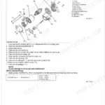
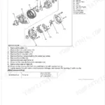
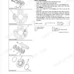
This document is a scanned copy of an original printed parts list. An OCR layer has been applied, so you can search and copy the full text, which is generally crisp and readable. Diagrams and illustrations are raster images, typical of scanned print materials, with labels that are mostly clear. Page conditions vary, showing some background discoloration, minor marks, and slight skewing on certain pages. Notably, page 45 is a blank filler page.

Reviews
There are no reviews yet.