


This is the Kubota B6000, B6000E, and B6000E-T service manual, the factory workshop reference for these compact tractors and their 2-cylinder ZL600 diesel engine. Its 52 pages take you past basic operation into real repair, with disassembly and assembly procedures for the major systems.
You get detailed sections on the engine, battery and electrical parts, front axle and 4-wheel drive, steering handle, clutch, transmission and speed change gears, hydraulic system, PTO, and three-point hitch. A maintenance check-list and a tractor maintenance standard give troubleshooting steps and the wear limits and clearances you need when rebuilding.
For a mechanic or a hands-on owner tearing into a B6000, this PDF download supplies the torque figures, adjustment values, and step by step procedures to pull, repair, and reassemble the tractor correctly. View it on any device or print the pages you need.
Complete the set for your B6000, B6000E, B6000E-T
- Parts Catalog: Kubota B6000 Parts Manual
- Operator Manual: Kubota B6000 Tractor Operator Manual (incl. Wiring)
What's Inside This Manual
| System | Pages | Key Topics |
|---|---|---|
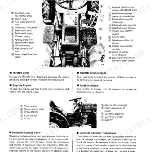
| Outside Views | Acceleration Lever, Hydraulic Control Lever, Brake Pedal | |
| Features | Compact and Powerful 2-Cylinder Diesel Engine !, Unique Spherical Combustion Chamber!, Starts Up at Once by Battery-Starter! | |
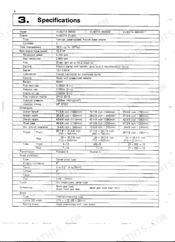
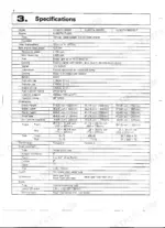
| Specifications | Engine Specifications, Dimensions, Transmission Specifications, Traveling Speeds | |
| Engine | Performance Curve of Kubota Model ZL600 Diesel Engine, Fuel System, Lubrication System, Combustion System, Top Clearance, Air Cleaner, Main Component Parts, Idling Adjustment | |
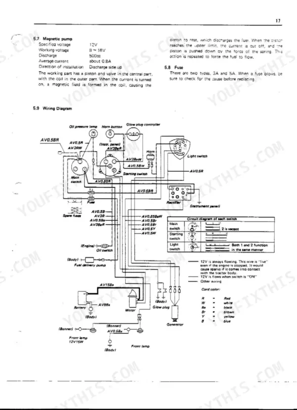
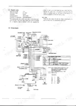
| Battery | Checks and Repair of Battery, Starter, Magnetic Pump | |
| Tractor | General Precautions, Outer Appearance | |
| Disassembly of Main Parts | Removal of the Front Axle, Removal of Engine, Disassembly of Brakes, Disassembly of Pedals, Disassembly of Frame Clutch Housing, Seat Control Rod and Lift Arm | |
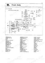
| Front Axle | Front Axle Inner Structure and Names of Parts, Front Axle Structure and Nomenclature, Disassembly and Assembly | |
| Steering Handle | Structure of Steering Handle, Steering Gear Case, Steering Wheel, Steering Shaft, Sector Shaft, Pitman Arm | |
| Clutch | Clutch Pedal, Brake Pedal, Clutch Adjustments, Differential Lock Pedal | |
| Transmission | Transmission Inner Structure and Name of Parts B6000, Transmission Inner Structure and Name of Parts B6000E, Differential Gear and Rear Axle Inner Structure and Name of Parts | |
| Speed Change | Speed Change Gear Structure for B6000, Speed Change Component Identification, Speed Change Gear Structure for B6000E | |
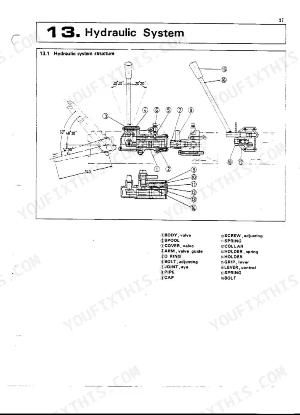
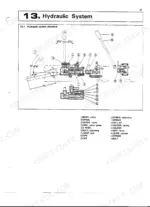
| Hydraulic System | Hydraulic System Structure, Hydraulic Lift, Control Valve | |
| PTO | PTO Shaft Diagram, PTO Shaft RPM, PTO Shaft Specifications | |
| Three-Point Hitch | Attaching of 3-Point Hitch, Three-Point Hitch Components Overview, 3-Point Hitch (Adjustment by Upper Link, Adjustment by Lift Rod, Check Chains) | |
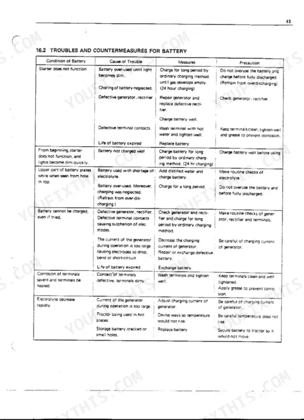
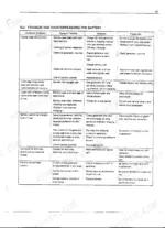
| Maintenance and Check-List | Troubles and Countermeasures for Battery, Troubles and Countermeasures for Engine | |
| Tractor Maintenance Standard | Front Wheel Alignment Specifications, Front Axle Specifications, Steering Specifications, Brakes Specifications, Main Clutch Specifications, Propeller Shaft Specifications |
Quick Reference Specifications
| Specification | Value | Page |
|---|---|---|
| Clutch pedal play (initial setting) | 0.098 to 0.12 in (2.5 to 3 mm) | p. 30 |
| Implement lift cheek rod length (adjustment) | 118mm | p. 39 |
| Implement lift large hole play (adjustment) | 30mm Play | p. 39 |
| Cylinder head nut tightening torque | 6~6.5 kg-m | p. 13 |
| Hydraulic oil filter replacement/cleaning frequency | Every 100hrs. | p. 45 |
| Hydraulic oil type | high quality #80 gear oil | p. 39 |
| Hydraulic oil capacity (transmission case oil) | 2.38GA (9 lit.) | p. 45 |
| Differential bevel gear backlash (general) | 0.13~0.25 mm | p. 34 |
| Backlash of diff Pinion and diff side gear | 0.0079~0.01 in (0.20~0.25mm) | p. 50 |
| Front axle drive shaft lubrication | about 40 grams of chassis grease | p. 23 |
| Front axle drive shaft universal joint type | Universal joint 1 is welded on. | p. 23 |
| PTO shaft location | Transmission case rear center | p. 6 |

