
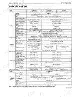
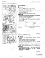
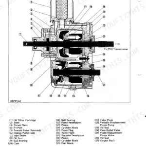
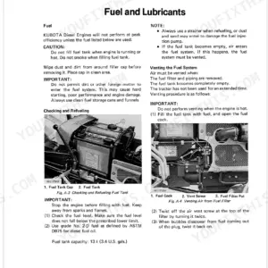
This Kubota B7400, B7500 Workshop Manual (OEM #No.97897-12490) stays on one machine: your compact tractor, hydrostatic or manual transmission. Eleven wiring diagrams map the starting circuit, charging system, glow plugs, and safety switches. Nine hydraulic schematics trace fluid through the HST, control valve, relief valve, and power steering circuit (B7500). The torque section alone runs 27 tightening specs across every major system: rear wheel hub mounting nuts at 108-125 N·m, front wheel mounting nuts at 77.5-90.1 N·m. Both the hydraulic oil filter and engine oil filter come out at 50 hours initial, then every 200 hours after. Service intervals sit on one page instead of scattered across forum threads. Search it by keyword, open it on a phone at the machine, and print the pages you need.
What's Inside This Kubota B7400, B7500 Manual
| System | Pages | Key Topics |
|---|---|---|
| Safety Instructions | 3-10 | Safety First, Before Servicing and Repairing, Safety Starting, Safety Working, Avoid Fires, Ventilate Work Area, Prevent Acid Burns, Dispose of Fluids Properly |
| General | 11-56 | Features, Tractor Identification, Handling Precautions For Electrical Parts And Wiring (Battery, Fuse, Connector, Handling Of Circuit Tester), Lubricants, Fuel And Cooling Water |
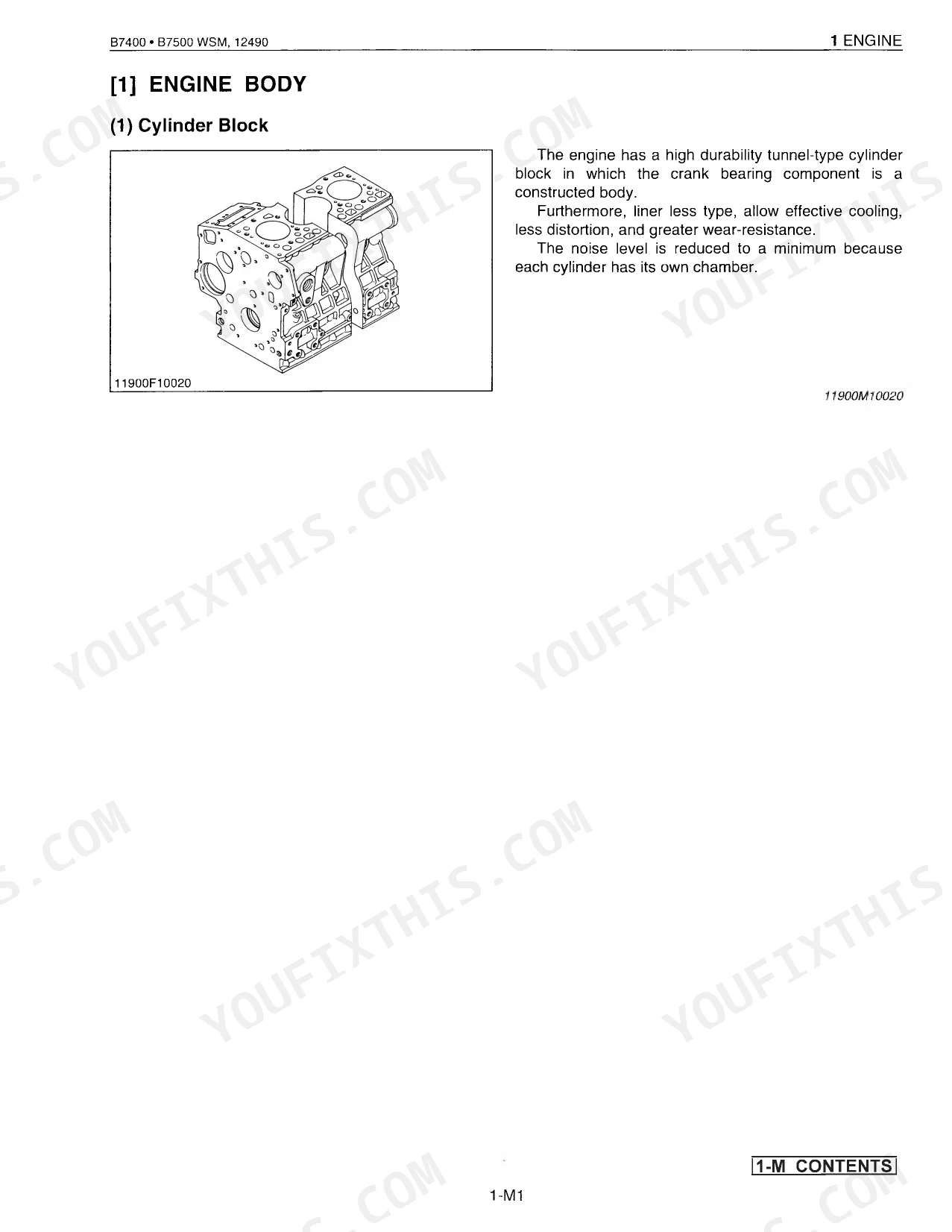
| Mechanism (Engine) | 57-79 | Engine Body (Cylinder Block, Cylinder Head, Crankshaft, Piston And Piston Rings, Connecting Rod, Camshaft, Fuel Camshaft, Rocker Arm, Intake And Exhaust Valve, Valve Timing, Flywheel, Air Cleaner, Muffler) |
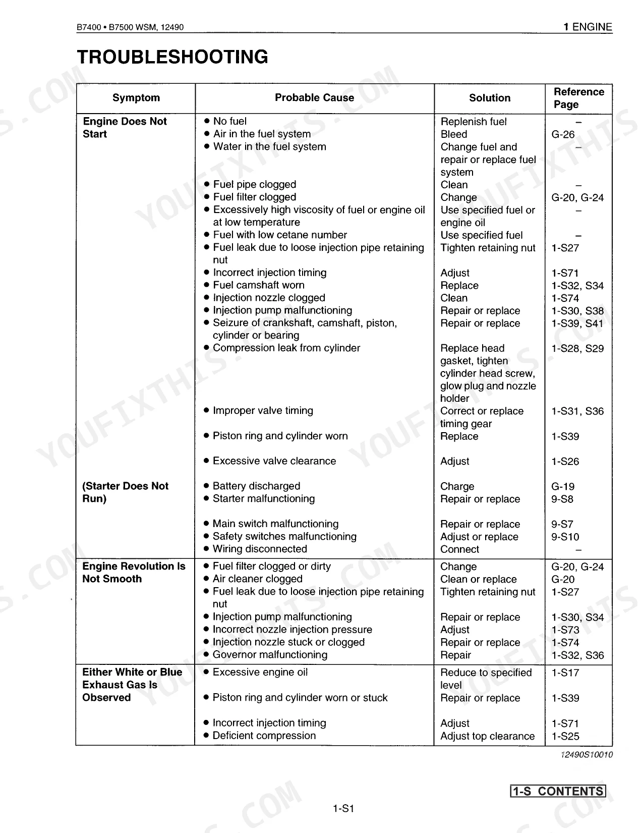
| Servicing (Engine) | 80-156 | Troubleshooting, Servicing Specifications [D722-E-D16], Servicing Specifications [D1005-E-D16], Tightening Torques, Checking, Disassembling And Servicing |
| Mechanism (Clutch) | 157-160 | Features, Linkage Mechanism, Operation |
| Servicing (Clutch) | 161-171 | Troubleshooting, Servicing Specifications, Tightening Torques, Checking, Disassembling And Servicing, Checking And Adjusting |
| Mechanism (Transmission) | 172-191 | Structure (Hydrostatic Transmission Type, Manual Transmission Type) |
| Servicing (Transmission) | 192-232 | Troubleshooting, Servicing Specifications, Tightening Torques, Checking And Adjusting, Disassembling And Assembling, Separating Engine From Clutch Housing |
| Mechanism (Rear Axle) | 233-234 | Features (Differential Gear Shaft, Ball Bearing, Rear Axle Case, Rear Axle, Spur Gear, Differential Gear, Spiral Bevel Gear, Differential System, Piston And Connecting Rod, Crankshaft, Servicing, Cylinder Head And Valves, Timing Gears, Camshaft And Fuel Camshaft, Cylinder) |
| Servicing (Rear Axle) | 235-238 | Tightening Torques, Checking, Disassembling, Separating Rear Axle Case (Draining Transmission Fluid, From Differential Gaer Case), Disassembling Rear Axle Case |
| Mechanism (Brakes) | 239-241 | Features (Wet Disc Brakes, Reduced Disc Wear, Stable Braking, Pedal Stroke Does Not Change Under Influence of Heat, Parking Brake, Fade, Relationship Between Temperature and Friction Coefficient of Brake Disc) |
| Servicing (Brakes) | 242-249 | Troubleshooting, Servicing Specifications, Tightening Torques, Checking, Disassembling And Servicing, Brake Pedal, Disassembling And Assembling |
| Mechanism (Front Axle) | 250-253 | Structures (Axle, Axle Flange, Bevel Gear, Differential Gear, Spiral Bevel Gear, Differential System), Front Wheel Alignment (Camber, Kingpin Angle, Caster), Toe-in |
| Servicing (Front Axle) | 254-265 | Troubleshooting, Servicing Specifications, Tightening Torques, Checking, Disassembling And Servicing, Checking And Adjusting |
| Mechanism (Steering) | 266-274 | Manual Steering System (Bearing, Sector Shaft, Steering Gear Case, Top Cover, Worm Shaft, Ball Nut, Ball Guide, Screw, Ball, Pitman Arm) |
| Servicing (Steering) | 275-292 | Troubleshooting, Servicing Specifications, Tightening Torques, Checking, Disassembling And Servicing |
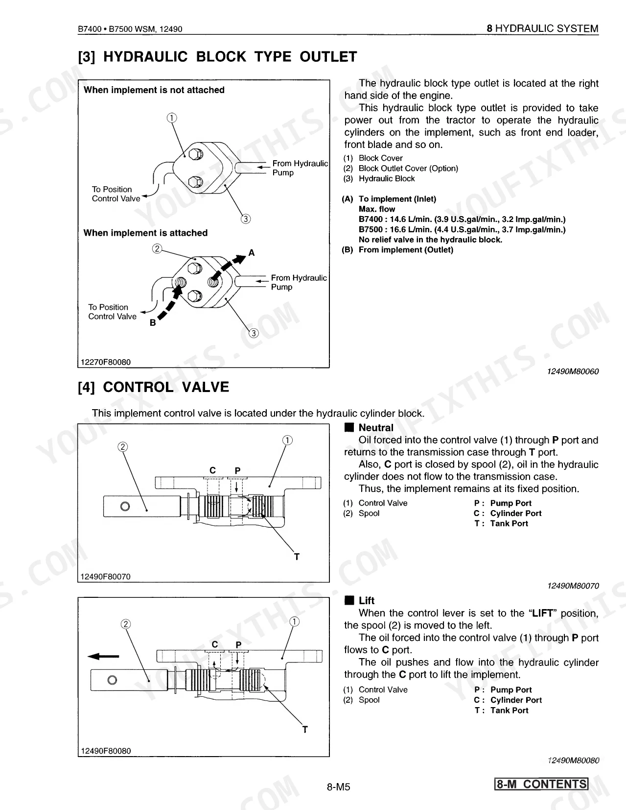
| Mechanism (Hydraulic System) | 293-302 | Hydraulic Circuit, Hydraulic Pump, Hydraulic Block Type Outlet, Control Valve, Relief Valve, Feedback Linkage For Position Control, Hydraulic Cylinder |
| Servicing (Hydraulic System) | 303-314 | Troubleshooting, Servicing Specifications, Tightening Torques, Checking, Disassembling And Servicing |
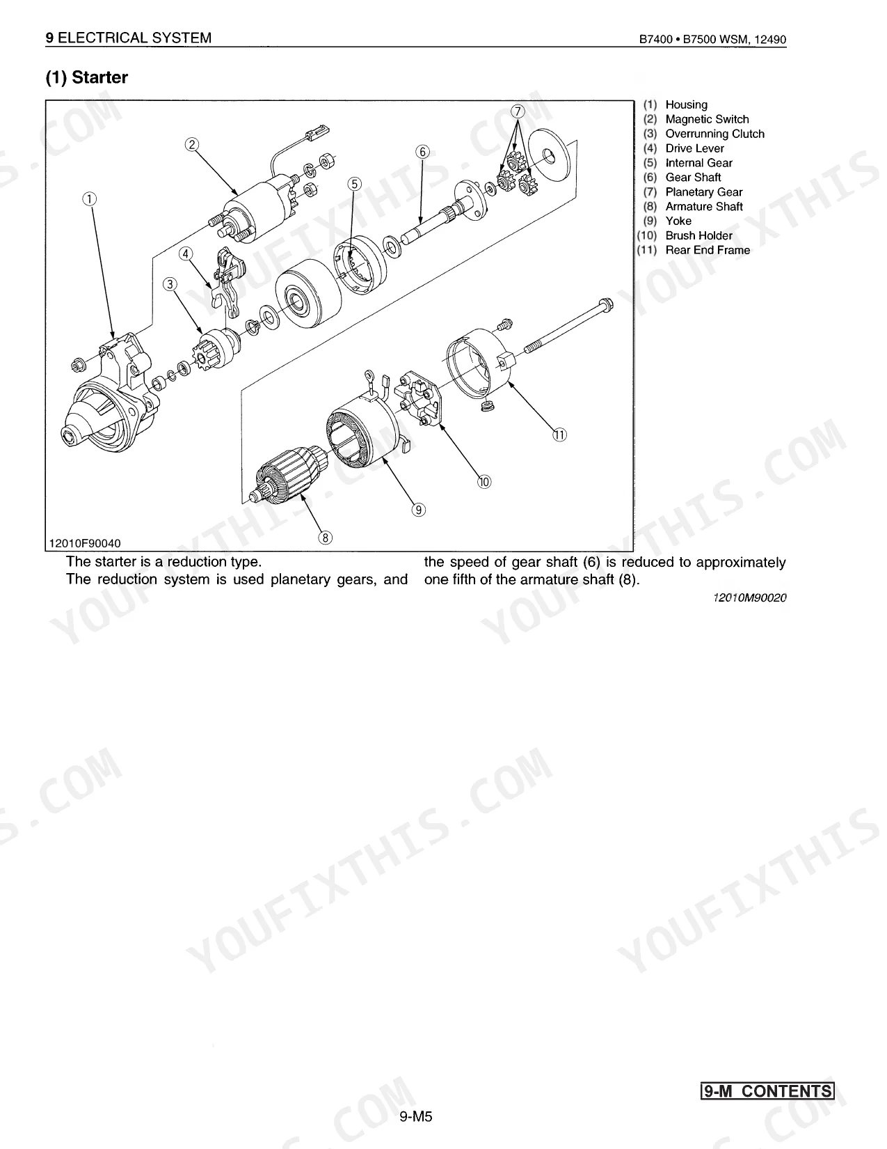
| Mechanism (Electrical System) | 315-329 | Wiring Diagram And Electrical Circuit, Starting System (Starter, Glow Plug, Safety Switch), Charging System (Ac Dynamo, Regulator) |
| Servicing (Electrical System) | 330-347 | Troubleshooting, Servicing Specifications, Tightening Torques, Checking, Disassembling And Servicing, Battery (Checking) |
Quick Reference Specifications
| Specification | Value | Page |
|---|---|---|
| Front wheel mounting nut torque | 77.5 to 90.1 N·m (7.9 to 9.2 kgf·m, 57.1 to 66.5 ft-lbs) | p. 20 |
| Rear wheel hub mounting nut torque | 108 to 125 N·m (11.0 to 12.8 kgf·m, 80 to 93 ft-lbs) | p. 20 |
| Hydraulic oil filter (for HST) replacement interval | Initial 50 Hours, Every 200 Hours | p. 21 |
| Hydraulic oil filter replacement interval | Initial 50 Hours, Every 200 Hours | p. 21 |
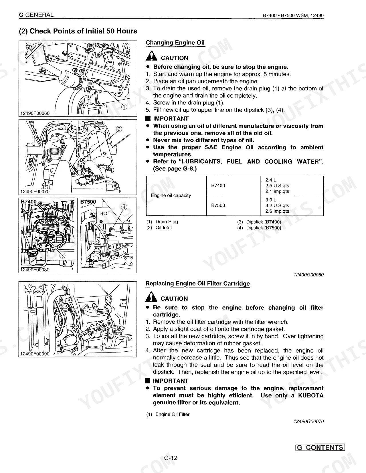
| Engine oil filter replacement interval | Initial 50 Hours, Every 200 Hours | p. 21 |
| Fuel filter element cleaning interval | Every 50 Hours | p. 21 |
| Fuel filter element replacement interval | Every 400 Hours | p. 21 |
| Air cleaner primary element cleaning interval | Every 50 Hours | p. 21 |
| Air cleaner primary element replacement interval | Every 1 Year or every 6 times of cleaning | p. 21 |
| Battery capacity at 5H.R (A.H.) | 36 | p. 30 |
| Battery reserve capacity (min.) | 71 | p. 30 |
| Starter M terminal nut torque | 8.8 to 11.8 N·m (0.9 to 1.2 kgf·m, 6.5 to 8.7 ft-lbs) | p. 95 |
Kubota B7400, B7500 Common Problems This Manual Covers
Kubota B7500 won't crank or starts intermittently, clicks once or starter spins without catching p. 330
Check battery voltage: it must read more than 12 V (page 99). Verify all safety switches are closed and the seat switch contacts are intact. Test the starter relay; with battery voltage applied across terminals 2-4, continuity across 1-3 should read 0 ohm (page 103). If both check out, follow the electrical system troubleshooting procedures at page 330.
Manual Section: Servicing (Electrical System)3-point hitch won't lift implement to full height or raises very slowly p. 303
Verify hydraulic fluid level first; top off if low. Pull the hydraulic filter and inspect for contamination; replace it at the initial 50-hour service and every 200 hours after (page 21). Trace the relief valve and control valve linkage with the hydraulic system troubleshooting steps on page 303. If lifting force stays weak, the pump needs bench inspection.
Manual Section: Servicing (Hydraulic System)Clutch pedal feels spongy, slips under load, or drags when fully depressed p. 161
Measure clutch pedal free travel at the stopper bolt: spec is 1.0 to 1.5 mm (page 26). If out of range, adjust the linkage per the checking and adjusting procedures on page 161. A clutch that still slips after correct adjustment needs disc inspection for oil contamination or wear; disc removal and measurement specs are in the same section.
Manual Section: Servicing (Clutch)Engine temperature gauge climbs to red during mowing or loader work
Press the fan belt at its midpoint: it should deflect 7 to 9 mm (page 32). Clear the radiator screen and cooling fins of dirt, grass, and chaff. Confirm coolant level and check hoses for leaks. With belt tension and coolant good, work the overheating branch of the engine troubleshooting section.
Manual Section: Servicing (Engine)Oil pressure warning lamp stays on at operating RPM or engine knocks
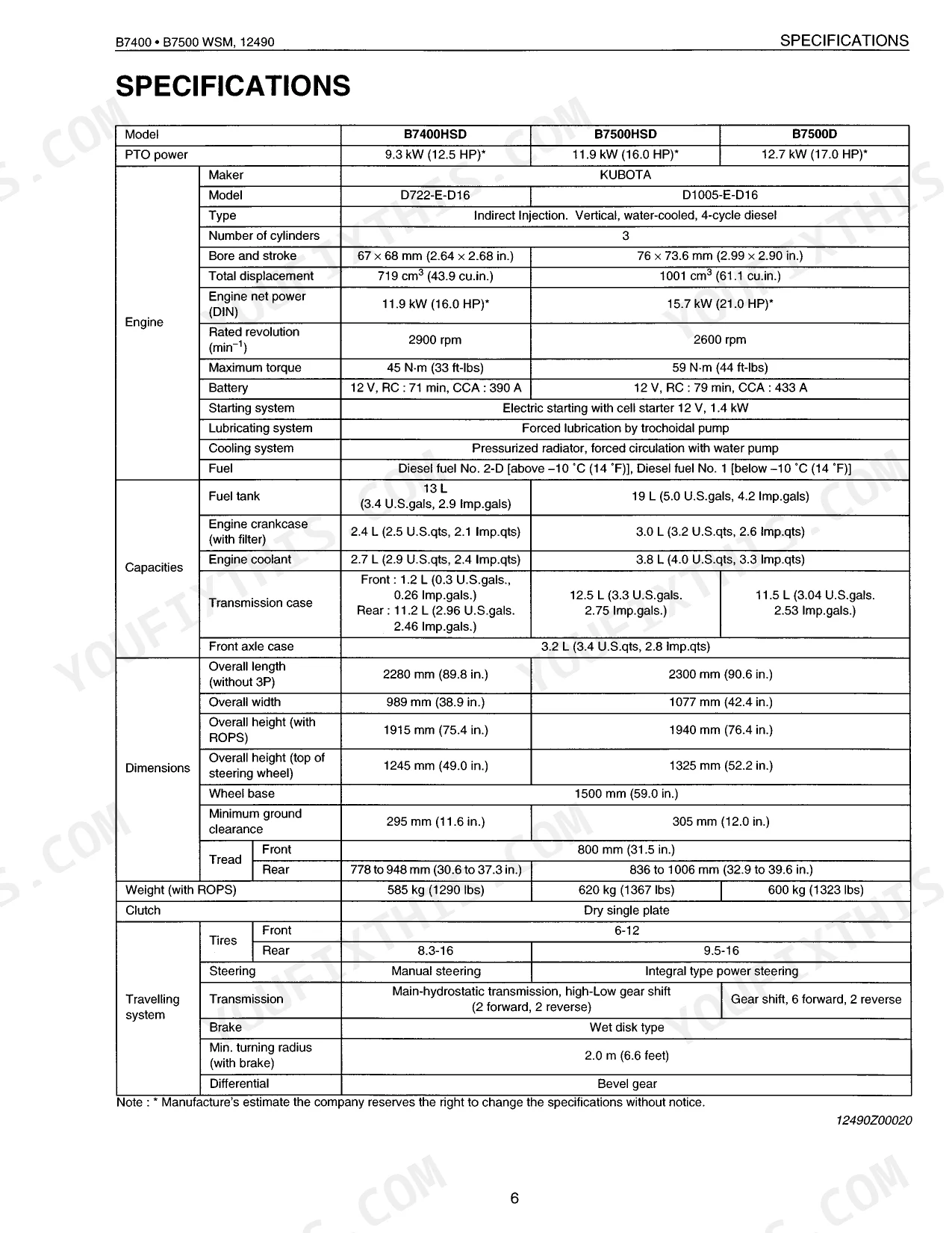
Stop and check oil level immediately; don't restart until it's confirmed. Normal idle oil pressure is 49 kPa or more, and a reading below that with correct level points to pump or bearing wear. Fill capacity is 2.4 L (B7400HSD) or 3.0 L (B7500HSD, B7500D) with filter (page 19). Work through engine troubleshooting to isolate the fault.
Manual Section: Servicing (Engine)Hydrostatic transmission loses drive in one direction or operates harshly under load p. 192
Check HST fluid level and condition before diagnosing internal faults. Pull the HST oil filter and inspect for metallic debris; it must be replaced at the initial 50-hour service and every 200 hours after that (page 21). Verify fluid is not overheated or discolored. Follow the hydrostatic transmission troubleshooting procedures on page 192 to pinpoint pump or motor wear.
Manual Section: Servicing (Transmission)Frequently Asked Questions
How do I reset the Kubota B7400/B7500 PTO or safety switch?
If any test fails, adjust or replace the affected safety switch. Set each linkage first: fully depress the clutch pedal, place the speed control pedal (HST Type) or main gear shift lever in “NEUTRAL,” and shift the PTO gear shift lever to “OFF.”
How do I reset the hydrostatic transmission on a Kubota B7500?
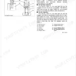
Resetting it means adjusting the neutral position. Disengage the front wheel drive lever, lift the rear wheels off the ground, and run the engine at low idle. Loosen the neutral adjuster setting screw (1), turn the adjuster (2) clockwise until the rear wheels run reverse, then counterclockwise until they stop. Hold the adjuster with its groove centered between the marks and tighten the screw (1).
What are the torque specs for Kubota B7400/B7500 wheel bolts, head bolts, or loader mounting bolts?
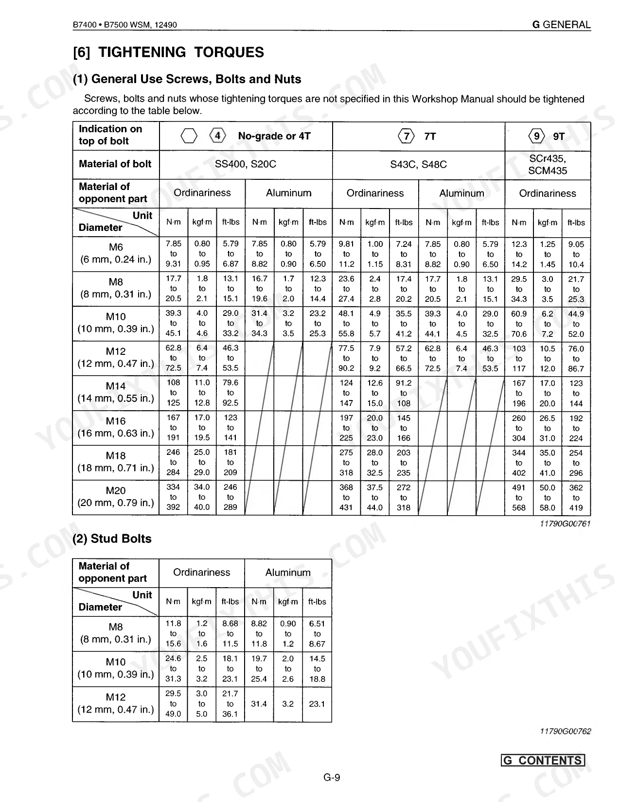
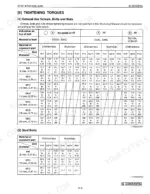
Front wheel mounting nut: 77 to 90 N·m (57.2 to 66.5 ft-lbs). Rear wheel hub mounting nut: 108 to 125 N·m (80 to 93 ft-lbs). Cylinder head screw runs 37.2 to 42.1 N·m (28.0 to 31.7 ft-lbs) on the D722 and 63.7 to 68.6 N·m (47.0 to 50.6 ft-lbs) on the D1005. Loader mounting bolt torque isn't listed in this manual.
What does a flashing warning light or error code mean on a Kubota B7400/B7500?
The Easy Checker system warns with indicator lamps, not alphanumeric codes. The Charge Lamp lights when the charging system isn't working properly. The Pre-heat Indicator Lamp lights with the key switch in the “Pre-heat” position. The Oil Pressure Lamp lights when engine oil pressure drops low, below roughly 49 kPa (7.1 psi).
How quickly can I access this Kubota B7400, B7500 manual after buying?
It's a 347-page searchable PDF, ready the moment you buy. Open it on any device, including your phone out at the machine. Nothing ships, nothing to wait on.
Are there any print restrictions on this Kubota B7400, B7500 manual?
No restrictions at all. Print individual pages, full chapters, or the entire manual. The PDF is completely unlocked.
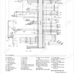
Can I find wiring schematics in this Kubota B7400, B7500 manual?
Yes. You'll find full electrical schematics with wire routing diagrams, connector identification, and circuit descriptions.
Document Quality
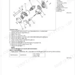
This document is a scanned PDF that includes an OCR layer, enabling you to search and copy the full text from all pages. The text is consistently crisp and easy to read, presenting no legibility issues. Diagrams and illustrations are clear raster images, with labels generally sharp and readable across various zoom levels. The pages are clean, showing no significant scan artifacts, stains, or skewed content. You will find that all pages contain relevant information, with no notable blank or filler pages.

Reviews
There are no reviews yet.