


This Kubota L3240–L5740 Series Service Manual (OEM #9Y111-03690) carries factory-correct procedures for eight tractors: the L3240-3, L3540-3, L3940-3, L4240-3, L4740-3, L5040-3, L5240-3, and L5740-3. The 706 pages include full wiring diagrams for the complete electrical system, hydraulic schematics showing fluid routing across every circuit, troubleshooting charts, error code tables, and step-by-step disassembly and assembly procedures from engine through cabin HVAC. Torque figures and clearance charts give exact numbers for every fastener and gap, and the calibration and test-value pages let you confirm the repair held. An L3240-3 holds 5.7 L of engine oil with filter; an L3940-3 or L4240-3 takes 8.2 L. With the machine down, the bookmarks and keyword search drop you onto the right page fast.
What's Inside This Kubota L3240–L5740 Series Manual
| System | Pages | Key Topics |
|---|---|---|
| I Information | 3-25 | - |
| G General | 26-105 | Tractor Identification, General Precautions, Handling Precautions for Electrical Parts and Wiring, Lubricants, Fuel and Coolant, Tires |
| Engine | 106-191 | EGR Valve, EGR Cooler, Cylinder Head, Timing Gears, Camshaft, Fuel Camshaft, Piston, Connecting Rod |
| Clutch | 192-218 | Clutch Pedal, Clutch Disc Boss, Clutch Disc, Diaphragm Spring, Pressure Plate, Release Holder, Clutch Lever |
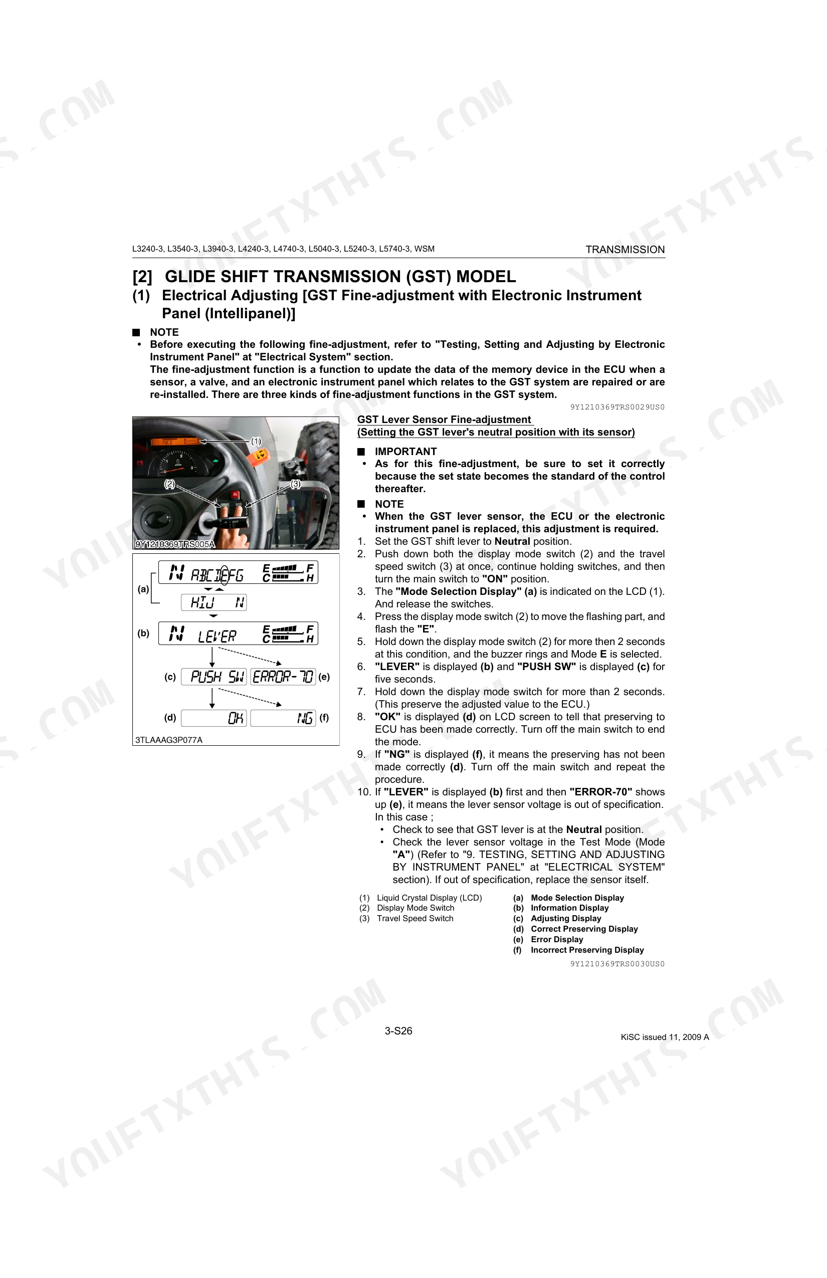
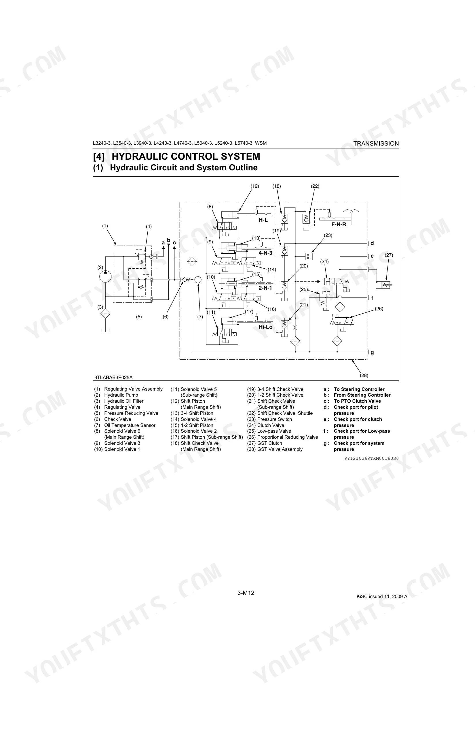
| Transmission | 219-398 | Manual Transmission Model, Glide Shift Transmission (Gst) Model, Hydrostatic Transmission (HST) Model, PTO System, Shift Linkage Mechanism, Electrical Control System, Hydraulic Control System, Gst Clutch |
| Rear Axle | 399-410 | Preparation, Disassembling and Assembling |
| Brakes | 411-427 | Brake Case, Brake Cam Lever, Parking Brake Lever, Brake Pedal, Brake Rod, Brake Lever Link, Turnbuckle, Cam Plate |
| Front Axle | 428-458 | Propeller Shaft, Power Steering Hoses, Steering Cylinder, Axle Flange, Bevel Gear, Bevel Gear Shaft, Bevel Gear Case |
| Steering | 459-478 | Steering Wheel, Steering Joint Shaft, Hydraulic Pump, Steering Controller, Steering Cylinder, Tie-Rod, Piston Rod, Cylinder Tube |
| Hydraulic System | 479-533 | Hydraulic Pump, Three Point Hitch Hydraulic System, Front Loader Control Valve Assembly, Auxiliary Control Valve, Safety Valve, Hydraulic Cylinder, Rear Hydraulic Block |
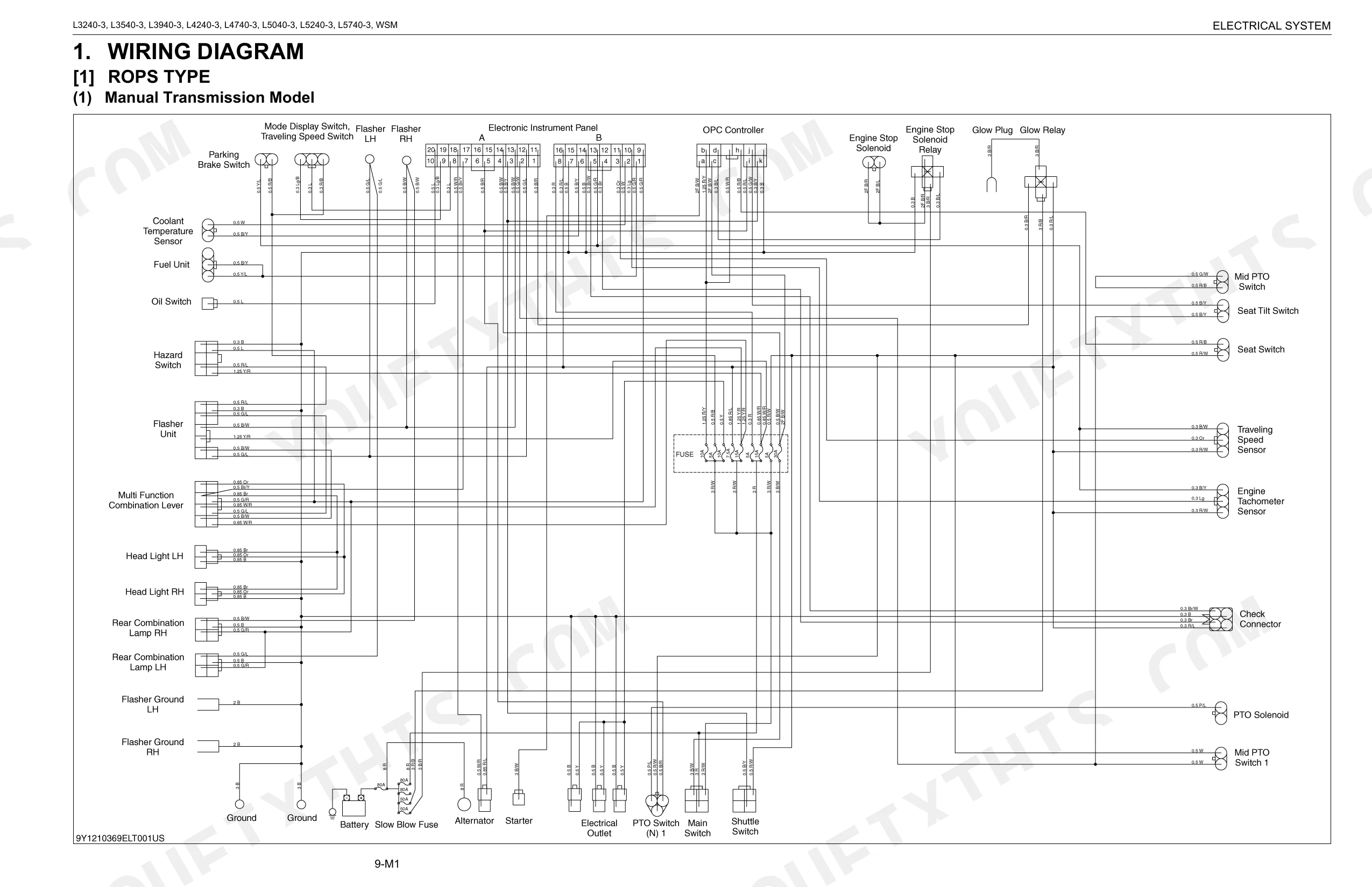
| Electrical System | 534-647 | Wiring Diagram, Electronic Control Panel, Engine Starting System, Stopping System, Manual Transmission Model, Gst Model, HST Model, ROPS Type |
| Cabin | 648-706 | Air Conditioner System, Electrical System, Air Conditioner Relay, Blower Relays, Compressor Relay, Manifold Gauge Set, Refrigerant Charging Hose, Vacuum Pump Adaptor |
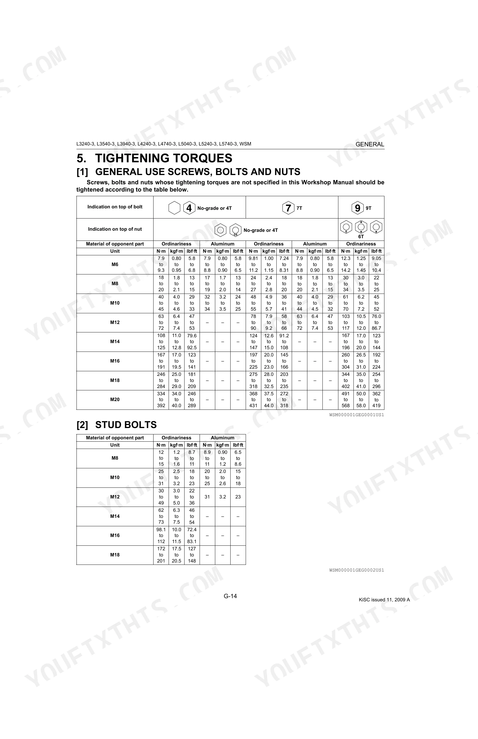
Every system also includes tightening torques and troubleshooting.
Quick Reference Specifications
| Specification | Value | Page |
|---|---|---|
| L3240, L3540 | ||
| Fuel tank capacity | 44 L (11.6 U.S.gals, 9.68 Imp.gals) | p. 36 |
| L3940, L4240 | ||
| Fuel tank capacity | 50 L (13.2 U.S.gals, 11.0 Imp.gals) | p. 36 |
| L3240-3 | ||
| Engine Oil Capacity (with filter) | 5.7 L | p. 47 |
| L3540-3 | ||
| Engine Oil Capacity (with filter) | 6.7 L | p. 47 |
| L3940-3, L4240-3, L4740-3 | ||
| Engine Oil Capacity (with filter) | 8.2 L | p. 47 |
| L5040-3, L5240-3, L5740-3 | ||
| Engine Oil Capacity (with filter) | 9.4 L | p. 47 |
| L3240-3, L3540-3 | ||
| Fuel Tank Capacity | 44 L | p. 46 |
| L3940-3, L4240-3 | ||
| Fuel Tank Capacity | 50 L | p. 46 |
| L4740-3, L5040-3, L5240-3, L5740-3 | ||
| Fuel Tank Capacity | 54 L | p. 46 |
| All Models | ||
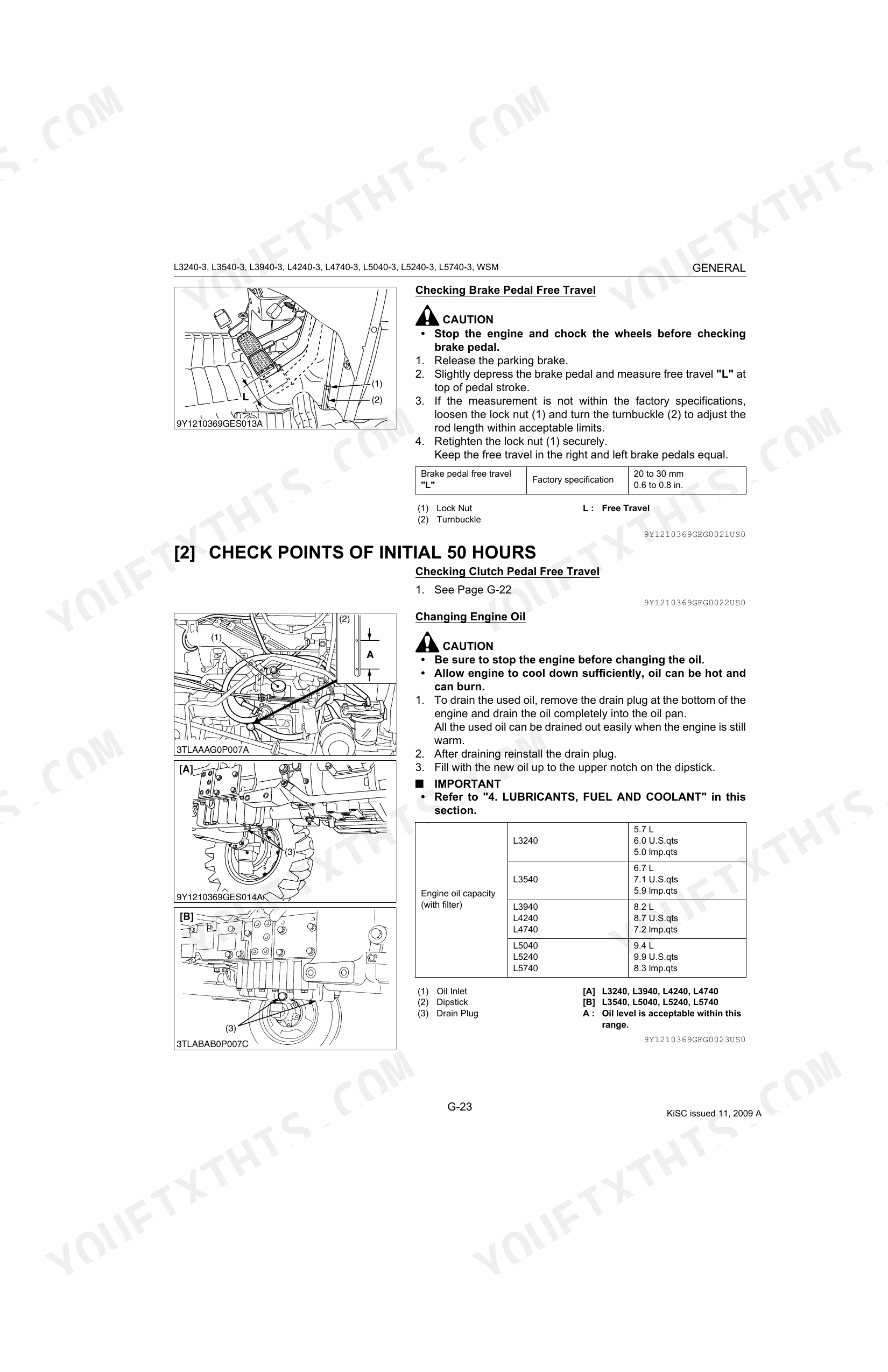
| Clutch Pedal Free Travel | 20 to 30 mm | p. 49 |
| Brake Pedal Free Travel | 20 to 30 mm | p. 50 |
| Rear Wheel Mounting Screws and Nuts Torque | 215 N·m | p. 53 |
Kubota L3240–L5740 Series Common Problems This Manual Covers
Kubota L3240-3 engine cranks but won't start in cold weather, glow lamp not lighting
Start with the engine troubleshooting flow, then confirm the glow plugs energize. Test compression next: allowable minimum is 2.5 MPa (page 115). If it reads low, inspect the cylinder wall and piston rings (page 112).
Manual Section: Engine TroubleshootingThree-point hitch won't lift under load, hydraulic pump whines continuously at max stroke
Top up the transmission oil before anything else; low fluid is the most common cause. Then pull the hydraulic troubleshooting procedures at page 479. The hydraulic oil filter is due every 400 hours (page 43); a clogged element chokes flow before the relief valve opens. If level and filter both check out, suspect a stuck control valve spool.
Manual Section: Hydraulic System Troubleshooting p. 479Uneven braking force when pedals locked together, tractor drifts right or left
Verify brake pedal free travel on both sides: spec is 20 to 30 mm (page 50). Adjust the weak side until travel matches the stronger pedal. If travel equalizes but pulling persists, inspect brake disc and cam plate for wear or warping (pages 416, 427).
Manual Section: Brakes Troubleshooting p. 411Clutch slipping under load or dragging at release, engagement feels rough and grabby
Measure clutch pedal free travel: correct range is 20 to 30 mm (page 49). If travel is outside spec, adjust the pushrod until it falls in range. Clutch adjustment is due every 100 hours (page 43). If slip continues with correct travel, the disc facing is worn and the assembly needs inspection per the clutch section at page 192.
Manual Section: Clutch Troubleshooting p. 192Fan belt squealing on startup, charging lamp on dash stays lit after warmup
Inspect fan belt tension first: correct deflection is 7 to 9 mm under a 98 N load (page 56). The maintenance schedule calls for a check every 100 hours (page 43). A loose belt cuts alternator output and lets coolant temperature climb. Replace the belt if the inner contact surface shows glazing, cracking, or fraying.
Manual Section: 1 Engine p. 56Frequently Asked Questions
What are the recommended service intervals?
Intervals depend on the component. The engine start system and wheel bolt torque get checked every 50 hours. Battery condition, fan belt, brake, clutch, and fuel line all run on a 100-hour cycle. p. 43
What fluids and capacities does this machine require?
The L3240/L3540 fuel tank holds 44 L (11.6 U.S.gals, 9.68 Imp.gals) of No. 2-D diesel. The L3240 engine crankcase takes 5.7 L (6.0 U.S.qts, 5.0 Imp.qts) of CF or CI-4 oil with the filter. The transmission case on both models uses 42 L (11.1 U.S.gals, 9.24 Imp.gals) of KUBOTA UDT or SUPER UDT fluid. p. 36
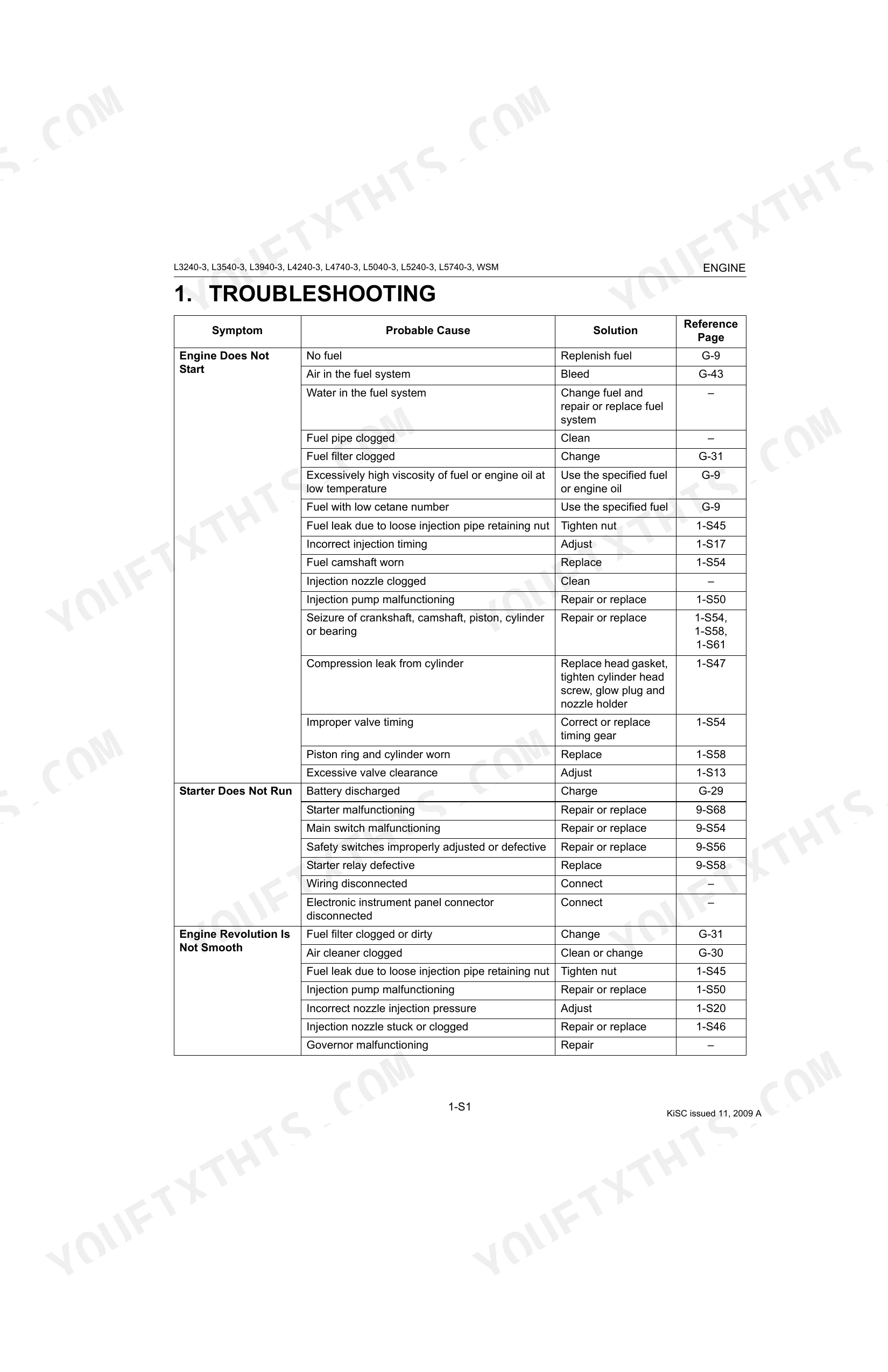
How to troubleshoot engine won't start?
A no-start usually traces to no fuel, air in the fuel system, or a clogged fuel filter. Top off the tank, bleed the lines, or change the filter as needed. A discharged battery or failed starter motor can also be the culprit. p. 112
What are the hydraulic system specifications?
On the L3240 2WD, the power steering relief valve is set to 8.0 to 9.0 MPa (82 to 91 kgf/cm2, 1200 to 1300 psi). Hydraulic pump delivery at no pressure runs above 18.6 L/min (4.91 U.S.gals/min, 4.09 Imp.gals/min) across the L3240, L3540, L3940, L4240, L4740, and L5740. p. 505
How will I receive this Service Manual?
Checkout delivers a 706-page searchable PDF right away. Open it on a laptop, tablet, or phone and carry it straight to the shop floor.
Is this Kubota L3240–L5740 Series Service Manual printable?
No restrictions at all. Print individual pages, full chapters, or the entire manual. The PDF is completely unlocked.
Are there hydraulic schematics in this Kubota L3240–L5740 Series manual?
Yes. The manual includes complete hydraulic schematics with flow diagrams, valve configurations, and pressure specifications.

Reviews
There are no reviews yet.