
Part of the Kubota Repair Manuals.
This Kubota Workshop Manual covers the L3560, L4060, L4760, L5060, L5460 and L6060 tractors, powered by Kubota's D1803-CR-E4, V2403-CR-E4 and V2403-CR-TE4 common rail diesel engines with after treatment. It runs 801 pages in English (publication 9Y111-08242) and gives troubleshooting, servicing specifications, tightening torques and step by step checking, disassembly and assembly.
The content is grouped by system: engine, clutch, transmission, rear axle, brakes, front axle, steering, hydraulics, electrical and cabin, including wiring diagrams and CAN communication. Owners and independent mechanics can diagnose faults, set valve clearance and pedal free travel, rebuild major assemblies and confirm the torque and pressure values for each model. It downloads as a fully searchable PDF you can read on any device or print by section for bench work.
What's Inside This Kubota L3560–L6060 Series Manual
| System | Pages | Key Topics |
|---|---|---|
| I Information | 5-27 | |
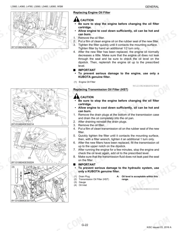
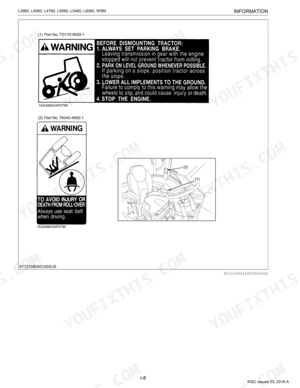
| G General | 28-113 | Tractor Identification, General Precautions, Handling Precautions for Electrical Parts and Wiring, Lubricants, Fuel and Coolant, Tightening Torques, Maintenance |
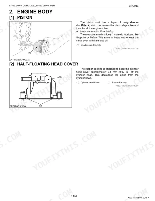
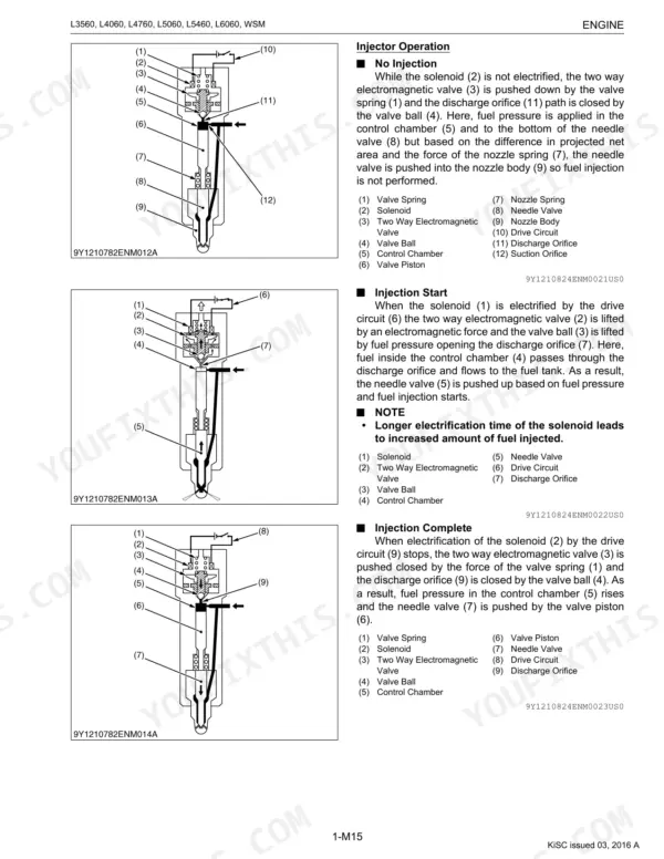
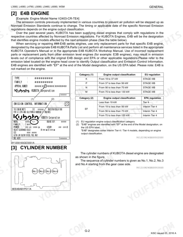
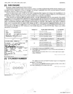
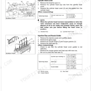
| Engine | 114-240 | Features, Engine Body, Lubricating System, Cooling System, Fuel System, EGR System, After Treatment System |
| Clutch | 241-274 | Clutch Disc, Pressure Plate Assembly, Release Fork, Shaft Case, Clutch Pedal Rod, Clutch Pedal, Release Bearing, Release Hub |
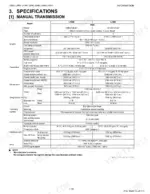
| Transmission | 275-453 | Manual Transmission, Glide Shift Transmission (Gst), Hydrostatic Transmission (HST), PTO System |
| Rear Axle | 454-465 | Rear Axle Case, Rear Wheel, ROPS, Cabin Mount Bracket |
| Brakes | 466-485 | Brake Pedal, Brake Rod, Brake Case, Rear Axle Case, Remote Control Valve, Brake Cam, Brake Cam Lever, Brake Disc |
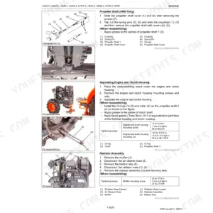
| Front Axle | 486-510 | Propeller Shaft, Power Steering Hoses, Steering Cylinder, Spiral Bevel Pinion Shaft, Differential Gear, Bevel Gear, Axle Flange |
| Steering | 511-527 | Structure, Hydraulic Circuit, Hydraulic Pump, Steering Controller, Steering Cylinder |
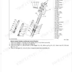
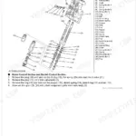
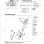
| Hydraulic System | 528-584 | Structure, Hydraulic Pump, Three Point Hitch Hydraulic Circuit, Rear Hydraulic Block, Position Control Valve, Front Loader Control Valve Assembly |
| Electrical System | 585-735 | Wiring Diagram, Electrical Circuit, Electronic Control Panel, Switches, Sensors, Engine Starting System and Stopping System, CAN (Controller Area Network) Communication |
| Cabin | 736-801 | Air Conditioner System, Outline of Air Conditioning System, System Control, Electrical System, Electrical Circuit, Compressor Relay, Blower Relays and Compressor Relay |
Quick Reference Specifications
| Specification | Value | Page |
|---|---|---|
| All Models | ||
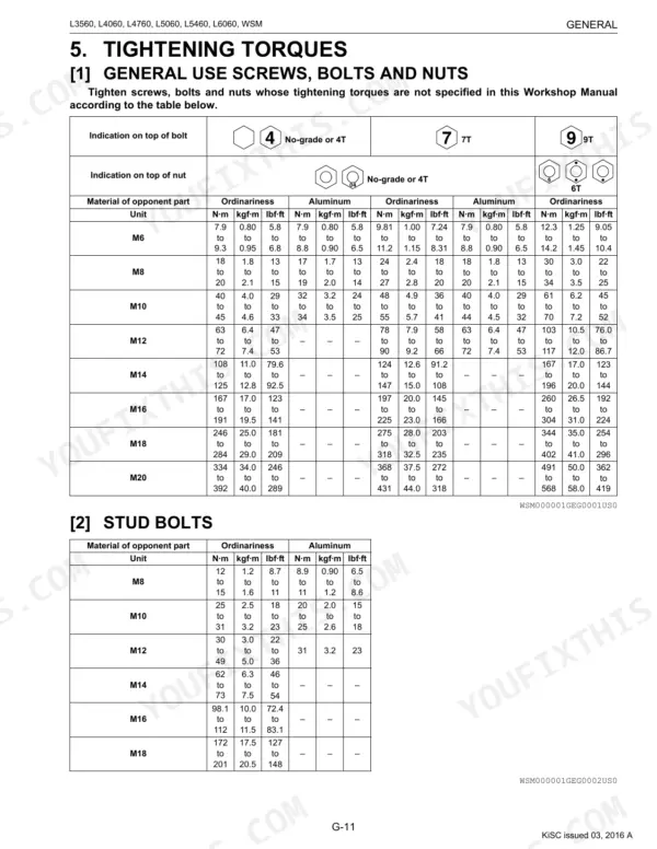
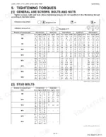
| M6 General Use Screws, Bolts and Nuts Tightening Torque | 7.9 to 9.3 N·m | p. 40 |
| M10 General Use Screws, Bolts and Nuts Tightening Torque | 40 to 45 N·m | p. 40 |
| Engine Valve Clearance (When Cold) | 0.18 to 0.22 mm | p. 151 |
| Engine Compression Pressure | 2.95 to 3.23 MPa | p. 151 |
| Engine Oil Pressure (At Rated Speed) | 300 to 440 kPa | p. 154 |
| Clutch Pedal Free Travel | 20 to 30 mm | p. 247 |
| Transmission GST System Pressure (Idling) | 2.30 to 2.50 MPa | p. 333 |
| Brake Pedal Free Travel | 15 to 20 mm | p. 472 |
| Front Axle Alignment Toe-in | 2 to 8 mm | p. 495 |
| Electrical Starter Terminal Nut Torque | 5.9 to 11 N·m | p. 648 |
| L3560, L4060 | ||
| Steering Relief Valve Setting Pressure | 10.7 to 11.7 MPa | p. 523 |
| L3560 | ||
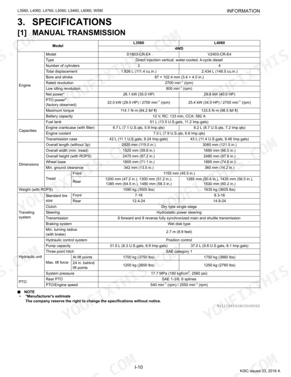
| Hydraulic Pump for 3 Point Hitch Delivery at No Pressure (Manual Transmission and GST) | Above 31.5 L/min. | p. 562 |
Kubota L3560–L6060 Series Common Problems This Manual Covers
Common rail or DPF faults
Rough running, warning lights or regeneration trouble on these Tier 4 engines point to the common rail fuel system or after treatment. The Engine section covers the fuel system, EGR and after treatment servicing.
Manual Section: 1 Engine p. 114Clutch slipping or dragging
Clutch pedal free travel outside the 20 to 30 mm range causes slipping under load or a clutch that will not release cleanly. The Clutch section carries the checking, adjusting and rebuild procedure.
Manual Section: 2 Clutch p. 241GST or transmission trouble
Harsh shifting, low system pressure or creep in the GST hydraulics signals internal wear. The Transmission section holds troubleshooting, servicing specifications and the disassembly and assembly steps.
Manual Section: 3 Transmission p. 275Weak hydraulics or loader lift
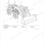
Slow three point hitch or front loader response, or a hitch that drops under load, usually means worn pump internals or a valve out of spec. The Hydraulic System section covers the pump, control valves and circuits.
Manual Section: 8 Hydraulic System p. 528Brake pedal free travel drift
Brake pedals that fall outside the 15 to 20 mm free travel spec drag or pull unevenly. The Brakes section gives the checking and adjusting steps and full brake disassembly.
Manual Section: 5 Brakes p. 466Steering wander or heavy effort
Play at the wheel or heavy steering points to the hydraulic pump, steering controller or cylinder. The Steering section covers the hydraulic circuit and each component in the power steering system.
Manual Section: 7 Steering p. 511Electrical or CAN faults
Dead panels, sensor errors or no start on these tractors trace to the electrical circuit, switches or CAN communication. The Electrical System section carries the wiring diagrams and component servicing.
Manual Section: 9 Electrical System p. 585Frequently Asked Questions
Which tractors does this manual cover?
It covers six Kubota models: the L3560, L4060, L4760, L5060, L5460 and L6060, all served by this single workshop manual with per model specifications noted where the tractors differ.
Is this the full workshop manual or a summary?
It is the complete 801 page Kubota workshop manual, publication 9Y111-08242, covering every system from engine to cabin with troubleshooting, specifications, tightening torques and repair procedures.
Does it cover the common rail and after treatment system?
Yes. The Engine section covers the common rail fuel system, EGR and after treatment system, along with the lubricating, cooling and fuel systems and full engine body servicing. p. 114
Are wiring diagrams and electrical troubleshooting included?
Yes. The Electrical System section provides wiring diagrams, the electrical circuit, control panel, switches, sensors, starting and stopping systems and CAN communication for all six models. p. 585
How will I receive this Kubota L3560–L6060 Series Workshop Manual?
You get a 801-page searchable PDF that downloads instantly after checkout. Open it on your laptop, tablet, or phone, bring it right to the shop floor.
Can I print pages of this manual for my own shop?
Yes. Print a chapter or just the pages for the job at hand, for use in your own shop. Any home or office printer works.
Does this Kubota L3560–L6060 Series Workshop Manual cover the hydraulic system?
Yes. The manual includes hydraulic circuit diagrams, system schematics, and component specifications with pressure ratings.




Reviews
There are no reviews yet.