


This Kubota M8540 and M9540 Workshop Manual (OEM #9Y021-13768) tracks one machine family: the 2006-2009 tractors, from cold-start diagnosis to cabin air conditioning. The hydraulic schematics trace full circuit routing through the lift arm, draft control linkage, and oil cooler relief valve, while the wiring diagrams map the electrical system, OPC, instrument panel, and lighting circuits. More than 200 pages of step-by-step procedures cover the engine, clutch, shuttle transmission, brakes, front axle, steering, and cab structure. Capacities are spelled out where you need them: 10.7 L of engine oil with filter, 9.0 L of coolant, and a 110 L fuel tank on the CABIN model. When your tractor is down, forum threads won't torque a differential for you. Download once, search by keyword, pull the spec, and get back to the repair.
What's Inside This Kubota M8540, M9540 Manual
| System | Pages | Key Topics |
|---|---|---|
| G General | 21-106 | General |
| 1 Engine | 107-211 | Cylinder Head and Valves, Fuel System, Lubricating System, Cooling System, Piston and Connecting Rod, Turbocharger |
| 2 Clutch | 212-270 | Clutch Pedal Free Travel, Traveling Clutch, PTO Clutch, Damper Disc, Release Holder and Lever |
| 3 Transmission | 271-370 | Shuttle Lever, Main Gear Shifting, Shuttle Valve, Shift Fork and Synchronizer, PTO Gear Section, Differential Gear |
| 4 Rear Axle | 371-390 | Planetary Gear, Brake Section, Rear Axle Assembly, Bearings |
| 5 Brakes | 391-416 | Traveling Brake, Parking Brake, Master Cylinder Assembly, Bleeding Brake System |
| 6 Front Axle | 417-449 | Front Axle, Bevel Gear Case, Differential Gear, Knuckle Shaft, Bearings |
| 7 Steering | 450-470 | Steering Controller, Steering Cylinder, Hydraulic Pump, Relief Valve Setting Pressure, Rod to Bushing |
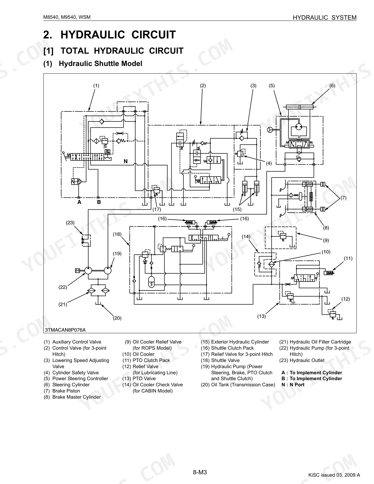
| 8 Hydraulic System | 471-522 | Hydraulic Pump, Relief and Safety Valve, Position and Draft Control Linkage, Hydraulic Cylinder, Oil Cooler Relief Valve, Lift Arm and Top Link Bracket |
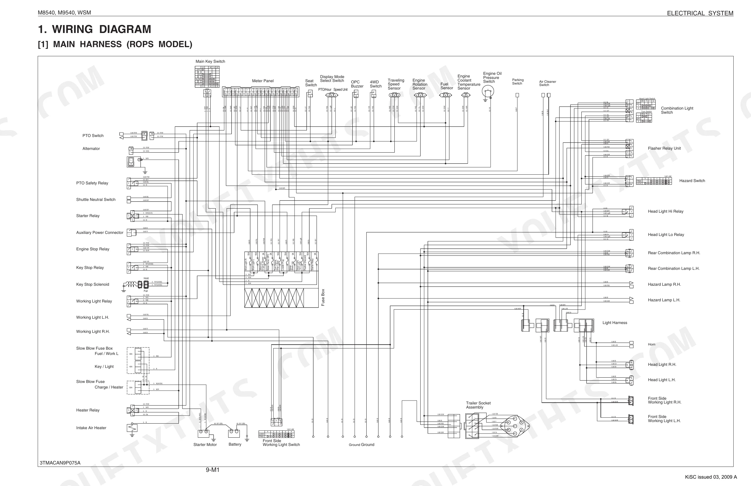
| 9 Electrical System | 523-596 | Wiring Diagram, Electrical Circuit Retailed Chart, Starting System, Instrument Panel, Opc (Operator Presence Control), Lighting System |
| 10 Cabin | 597-662 | Structure, Compressor, Air Conditioner Unit, System Control, Air Flow, Air Control Vent |
Quick Reference Specifications
| Specification | Value | Page |
|---|---|---|
| All Models | ||
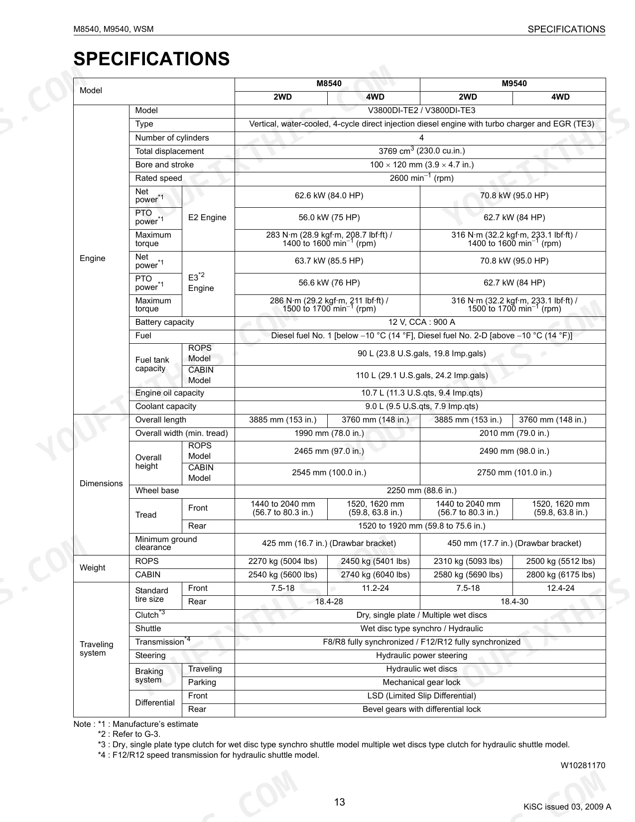
| Fuel tank capacity (ROPS Model) | 90 L (23.8 U.S.gals, 19.8 Imp.gals) | p. 15 |
| Fuel tank capacity (CABIN Model) | 110 L (29.1 U.S.gals, 24.2 Imp.gals) | p. 15 |
| Total displacement | 3769 cm3 (230.0 cu.in.) | p. 15 |
| Rated speed | 2600 min−1 (rpm) | p. 15 |
| Engine oil capacity | 10.7 L (11.3 U.S.qts, 9.4 Imp.qts) | p. 15 |
| Coolant capacity | 9.0 L (9.5 U.S.qts, 7.9 Imp.qts) | p. 15 |
| Hydraulic pump capacity | 64.3 L (17 U.S.gals, 14 Imp.gals) / min. | p. 16 |
| Hydraulic system pressure | 19.6 MPa (200 kgf/cm2, 2844.7 psi) | p. 16 |
| PTO speed | 540 min−1 (rpm) at 2205 min−1 (rpm) | p. 16 |
| Cylinder Head Surface Flatness (Allowable Limit) | 0.05 mm (0.0020 in.) | p. 132 |
| M8540 | ||
| Net power (E2 Engine) | 62.6 kW (84.0 HP) | p. 15 |
| M9540 | ||
| Net power (E2 Engine) | 70.8 kW (95.0 HP) | p. 15 |
Kubota M8540, M9540 Common Problems This Manual Covers
Overheats under heavy load, and coolant bubbles up in the recovery tank
Inspect the cylinder head for warping with a straightedge. Measure the surface flatness and confirm it stays within the allowable limit of 0.05 mm (0.0020 in.) on page 132. Replace the head gasket, then torque the bolts to specification.
Manual Section: Engine TroubleshootingImplement does not raise, or drops under its own weight when the control lever is moved
Test the hydraulic pump output with a flow meter. Confirm the pump reaches its rated capacity of 64.3 L (17 U.S.gals, 14 Imp.gals) / min. shown on page 16. Swap the hydraulic oil filter if the tractor has run past its 300 Hr maintenance interval.
Manual Section: Hydraulic System TroubleshootingExcessive transmission noise and gears clash when shifting between forward and reverse ranges
Drain the main case and check the fluid for metal shavings. Refill to the transmission case capacity of 60 L (63.4 U.S.qts, 52.8 Imp.qts) detailed on page 31. Confirm the every 600 Hr fluid change interval against the schedule on page 37.
Manual Section: Transmission TroubleshootingEngine revolution is not smooth and exhaust gas shows excessive white smoke during cold morning starts
Pull the valve cover and check the valve clearance with the engine cold. Set the clearance to 0.23 to 0.27 mm (0.0091 to 0.0106 in.) using a feeler gauge. If it still idles rough afterward, work through the troubleshooting procedures.
Manual Section: Engine TroubleshootingHydraulic fluid leaks from lines under the cab and pressure drops during loader operation
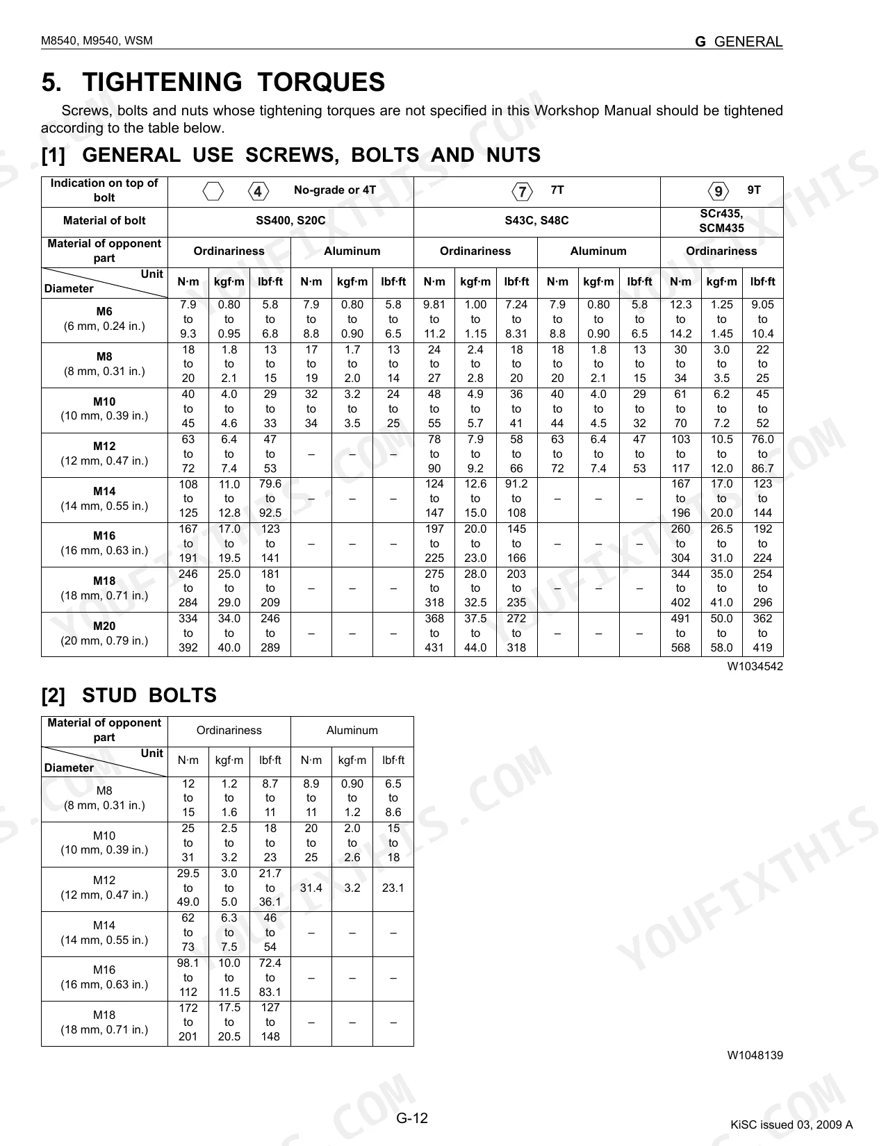
Examine the hydraulic lines for cracks or loose connections. Torque the hose fittings to 22.6 to 27.5 N·m (2.3 to 2.8 kgf·m, 16.6 to 20.3 lbf·ft) as specified on page 35. Trace the exact line routing on the hydraulic schematic before replacing any hoses.
Manual Section: Hydraulic System TroubleshootingFrequently Asked Questions
What are the recommended service intervals?
Service intervals run off the hour meter. The engine start system gets checked every 50 hours, battery condition every 100 hours, and engine oil changed every 300 hours. Longer intervals include replacing the air cleaner primary element every 1 year and flushing the cooling system every 2 years.
What fluids and capacities does this machine require?
Each system has its own fill. The fuel tank holds 90 L (23.8 U.S.gals, 19.8 Imp.gals) on ROPS models and 110 L (29.1 U.S.gals, 24.2 Imp.gals) on CABIN models, running No. 2-D diesel. The engine crankcase with filter takes 10.7 L (11.3 U.S.qts, 9.4 Imp.qts) of API Service Classification CF or CI-4 oil, and the transmission case holds 60 L (63.4 U.S.qts, 52.8 Imp.qts) of KUBOTA UDT or SUPER UDT fluid.
How to troubleshoot engine won't start?
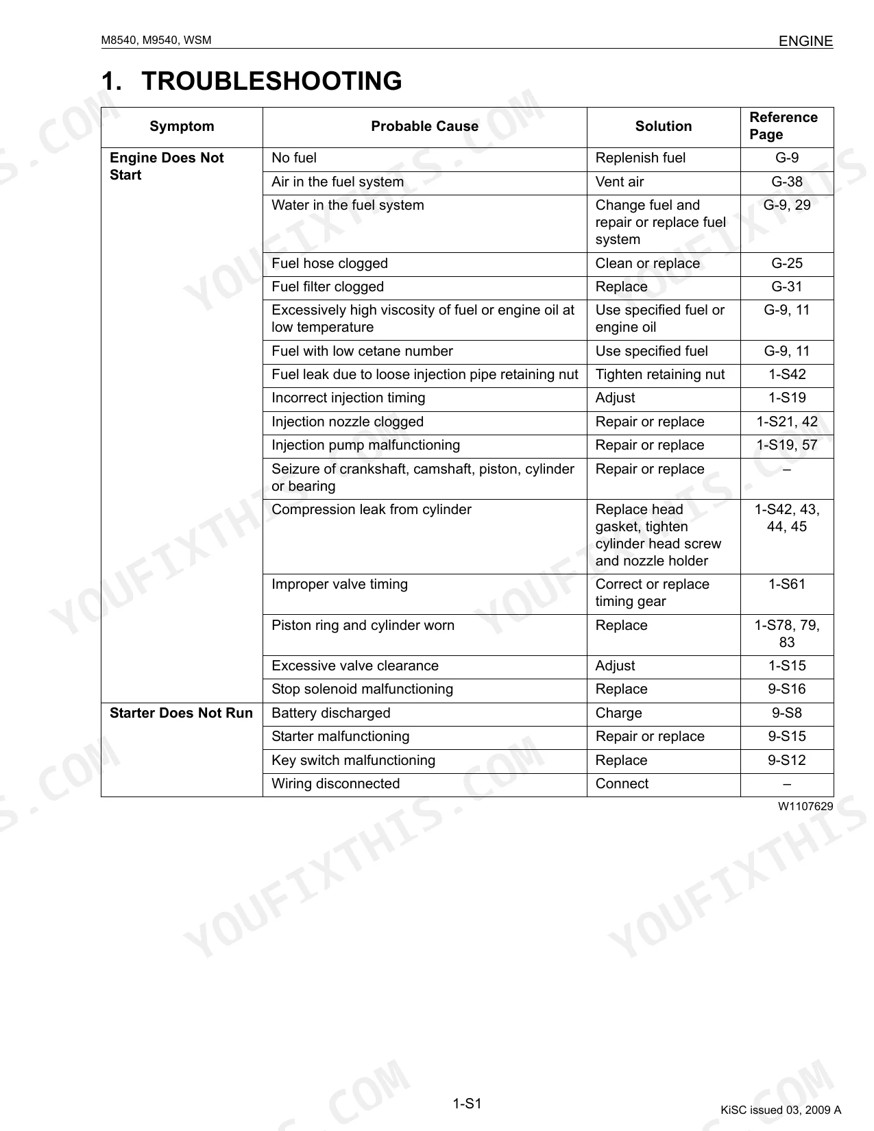
When the engine won't start, the usual culprits are no fuel (replenish, page G-9), air in the fuel system (vent it, page G-38), or a clogged fuel filter (replace, page G-31). It can also trace back to incorrect injection timing (adjust, page 1-S19) or a failing injection pump (repair or replace, page 1-S19, 57).
What are the hydraulic system specifications?
Two pumps feed the hydraulics. The power steering pump runs a rated pressure of 18.1 MPa (185 kgf/cm², 2631 psi) with delivery above 24.4 L/min., while the 3-point linkage pump is rated at 19.1 MPa (195 kgf/cm², 2770 psi) with delivery above 61.7 L/min. The relief valve setting pressure is 18.9 to 19.8 MPa (192 to 202 kgf/cm², 2730 to 2870 psi).
What format is this Kubota M8540, M9540 manual in?
Delivery is a 662-page searchable PDF, downloadable the moment checkout clears. Open it on a laptop, tablet, or phone and take it straight to the shop floor.
Can I print specific sections of this Kubota M8540, M9540 Workshop Manual?
Yes. The PDF carries no DRM, so you can print any page or section you need for the shop. It works with any standard printer.
Are there wiring harness diagrams in this Kubota M8540, M9540 manual?
Included. The Kubota M8540, M9540 Workshop Manual covers complete wiring harness diagrams, electrical circuits, and connector pinouts.
Document Quality
This is a native digital PDF document, allowing you to search and copy the full text content. All text is crisp and easy to read throughout the manual. Diagrams and illustrations are a mix; some are sharp vector graphics, while others are raster images or photos that may appear slightly pixelated when zoomed in, but their labels remain readable. The pages are clean with no notable scan artifacts, stains, marks, or skewed content. There are a few blank pages that serve as section dividers.


Reviews
There are no reviews yet.