


Finding the right part number the first time is the whole point of this Kubota TL420(B20) Parts Catalog. Across 17 sections, numbered parts lists sit beside exploded-view diagrams covering every assembly from the side frame and boom through the control valve, cylinders, and hydraulic tube routing. The boom and bucket cylinder sections drop to component level, listing individual tubes, rods, pistons, seal kits, and head assemblies for both left-hand and right-hand builds. Every entry carries a REF.No., Kubota part number, description, quantity, and interchange code, while country-specific remarks pin down which serial range a part fits. No more guessing at seal kits. Because the file is bookmarked and searchable, you can jump straight to boom cylinders or control valve components instead of paging through all 35.
What's Inside This Kubota TL420(B20) Parts Manual
| System | Pages | Key Topics |
|---|---|---|
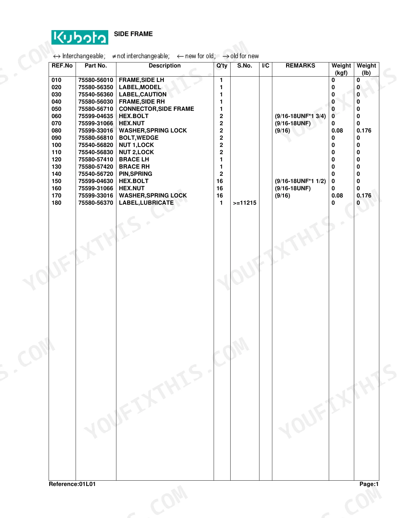
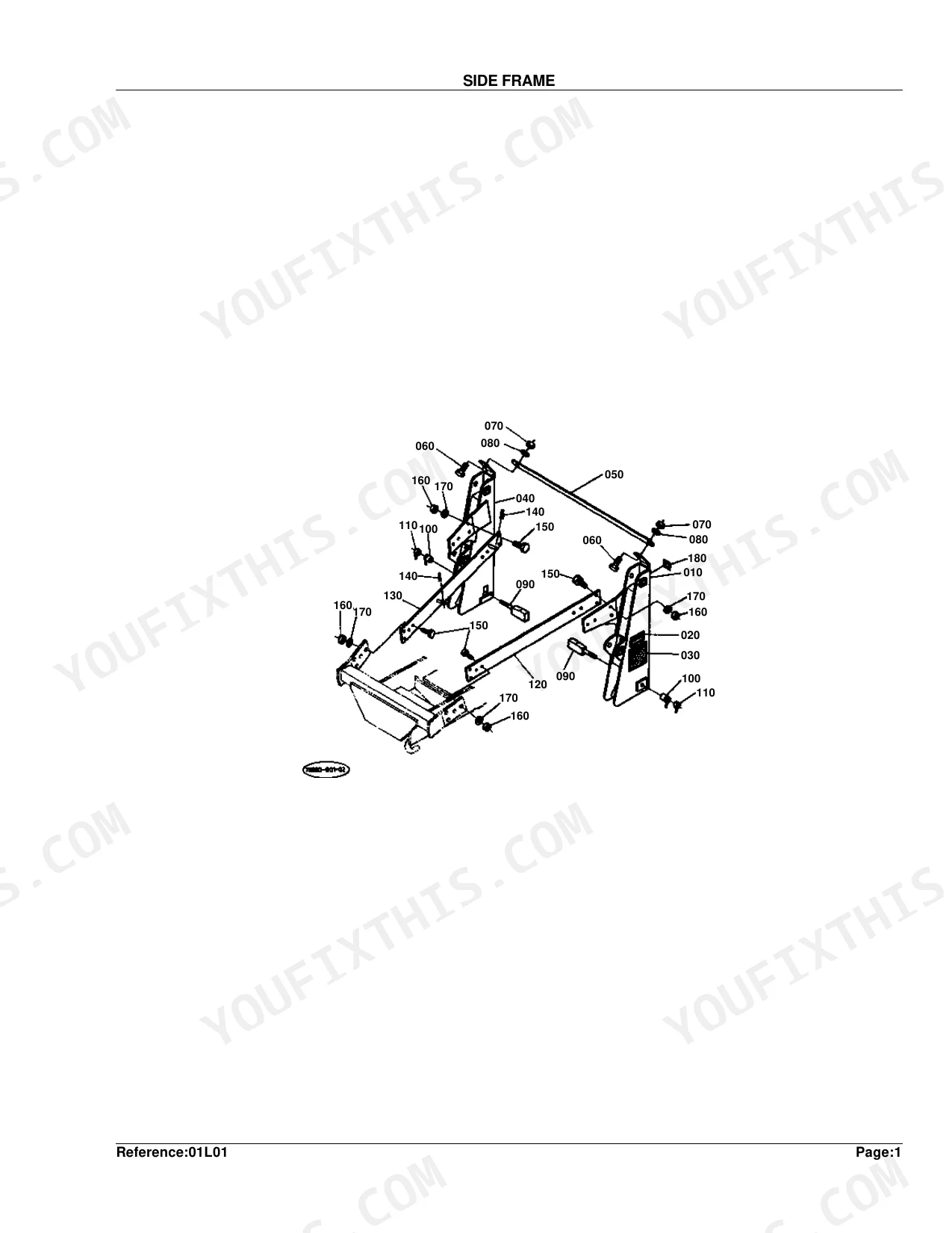
| Side Frame | 4-5 | Frame, Side Lh, Side Rh, Connector, Hex.Bolt, Washer, Spring Lock |
| Boom | 6-7 | Fitting, Grease, Assy Pin, Cir-Clip, External, Pin, Cotter, Link |
| Control Valve | 8-9 | Stay, Valve, Hex.Bolt, Washer, Spring Lock, Control, Assy Adapter |
| Control Valve (New Type) [Component Parts] | 10-11 | Valve, Control, Assy Inlet Section, Housing, Inlet, Assy Spool Section, Cap-Spool, O-Ring |
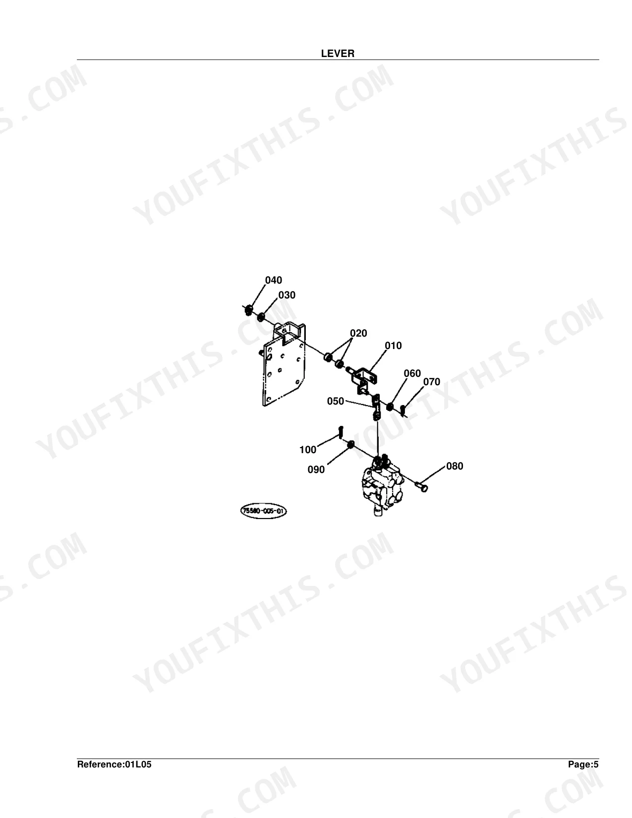
| Lever | 12-13 | Bushing, Washer, Plain, Cir-Clip, External, Rod, Pin, Cotter |
| Control Lever | 14-15 | Lever, Control, Grip, Pin, Clevis, Washer, Plain |
| Control Cover | 16-17 | Cover, Hex.Bolt, Washer, Spring Lock, Label, Control, Assy Limiter, Cushion |
| Link | 18-19 | Bushing, Washer, Plain, Cir-Clip, External, Rod, Pin, Cotter |
| Cylinder/Hydraulic Hose | 20-21 | Cylinder 1 Lh, Cylinder 1 Rh, Elbow, Clamp, Hose |
| Cylinder (Boom) Lh [Component Parts] | 22-23 | 1 Lh, Tube 1 Comp Lh, Rod 1 Comp, Head 1, Piston, Kit 1, Seal |
| Cylinder (Boom) Rh [Component Parts] | 24-25 | 1 Rh, Tube 1 Comp Rh, Rod 1 Comp, Head 1, Piston, Kit 1, Seal |
| Cylinder (Bucket) Lh [Component Parts] | 26-27 | 2 Lh, Tube 2 Comp Lh, Rod 2 Comp, Head 1, Piston, Kit 1, Seal |
| Cylinder (Bucket) Rh [Component Parts] | 28-29 | 2 Rh, Tube 2 Comp Rh, Rod 2 Comp, Head 1, Piston, Kit 1, Seal |
| Hydraulic Tube | 30-31 | Clamp, Hex.Bolt, Washer, Spring Lock |
| Delivery/Return Tube | 32-34 | Delivery Tube, Return Tube, Joint, Gasket, Clamp, Hydraulic Hose |
| Accessories and Service Parts | 35 | Operator'S Manual, Kit French, Label, Caution, Warning, Leveler |
Quick Reference Specifications
| Specification | Value | Page |
|---|---|---|
| WASHER, SPRING LOCK (REF.No 080) Weight | 0.08 kgf | p. 5 |
| WASHER, SPRING LOCK (REF.No 170) Weight | 0.08 kgf | p. 5 |
| WASHER, PLAIN (REF.No 030) Weight | 0.009 kgf | p. 13 |
| WASHER, PLAIN (REF.No 060) Weight | 0.002 kgf | p. 13 |
| PIN, COTTER (REF.No 050) Weight | 0.002 kgf | p. 15 |
| WASHER, PLAIN (REF.No 190) Weight | 0.002 kgf | p. 15 |
| WASHER, PLAIN (REF.No 080) Weight | 0.002 kgf | p. 17 |
| WASHER, PLAIN (REF.No 100) Weight | 0.002 kgf | p. 19 |
| WASHER, PLAIN (REF.No 120) Weight | 0.009 kgf | p. 19 |
Kubota TL420(B20) Common Problems This Manual Covers
Kubota TL420 boom cylinder seal kit part number needed, unsure whether left and right cylinders share the same kit p. 22
Open the exploded view on page 22 for the left boom cylinder and page 24 for the right. Each diagram breaks the assembly into Tube 1 Comp, Rod 1 Comp, Head 1, Piston, and Kit 1 Seal with separate reference numbers for Lh and Rh builds. Locate the part number stamped on your cylinder barrel to confirm left or right, then order Kit 1, Seal from the matching diagram. Do not assume the kits are interchangeable; the tube and rod part numbers differ between sides.
Manual Section: Cylinder (Boom) Lh [Component Parts]Control valve O-ring part numbers don't match the older parts diagram, new-type valve installed on machine p. 10
Check page 10 for the Control Valve (New Type) component parts diagram. This section lists the Inlet Section, Spool Section, Cap-Spool, and O-Ring as individually referenced assemblies. If page 8 shows a different valve layout, your machine has the updated valve; use only the reference numbers on page 10. Match the housing assembly number to your serial range before ordering to avoid receiving parts for the earlier valve design.
Manual Section: Control Valve (New Type) [Component Parts]Bucket cylinder seal kit hard to confirm, both cylinders look identical from outside the machine p. 26
Turn to page 26 for Cylinder 2 Lh and page 28 for Cylinder 2 Rh. Both diagrams list Kit 1, Seal but assign separate part numbers to Tube 2 Comp Lh and Tube 2 Comp Rh. Find the stamped number on the cylinder barrel to confirm your side, then order the seal kit from the correct diagram. Ordering from the wrong page risks receiving a kit built for the opposite cylinder, which will not seat correctly in the rod head.
Manual Section: Cylinder (Bucket) Lh [Component Parts]Loader control lever pivot bushing and plain washer part numbers needed to replace worn linkage hardware p. 12
Start with the Lever section on page 12. The diagram lists Bushing, Washer Plain, Cir-Clip External, Rod, Pin, and Cotter Pin as individual line items with reference numbers. Verify the correct plain washer on page 13: Ref. No. 030 weighs 0.009 kgf and Ref. No. 060 weighs 0.002 kgf. That weight gap confirms which washer fits your pivot before you order. For the upper control lever grip and clevis pin assembly, cross-reference page 14.
Manual Section: LeverHydraulic hose and elbow fitting part numbers unclear, multiple hose sizes run to the cylinders p. 20
Reference the Cylinder/Hydraulic Hose exploded view on page 20. The diagram identifies Cylinder 1 Lh, Cylinder 1 Rh, Elbow, Clamp, and Hose with individual reference numbers for each fitting and hose run. For the delivery and return lines, also check page 32, which covers Delivery Tube, Return Tube, Joint, Gasket, Clamp, and Hydraulic Hose assemblies across three pages. Match reference numbers from the correct diagram to avoid substituting a mismatched elbow or incorrect hose length.
Manual Section: Cylinder/Hydraulic HoseDelivery tube joint gasket and return line fitting part numbers needed after hydraulic overflow at the rear p. 32
Go to the Delivery/Return Tube section on page 32, which spans pages 32 to 34. The diagram breaks out Delivery Tube, Return Tube, Joint, Gasket, Clamp, and Hydraulic Hose with individual reference numbers at each connection point. Find the leaking joint in the diagram, note the Gasket reference number at that position, and add the adjacent Clamp reference to your order. A failed clamp is the common companion failure after a hydraulic fluid overflow.
Manual Section: Delivery/Return TubeFrequently Asked Questions
What are the replacement specifications for hydraulic fittings?
When it comes to grease fittings, the manual lists part number 75599-81521 at (1/4-28T.T.), along with 75540-63480 and 75599-81531 at (1/8-27PTF). These fittings show up across several hydraulic components, including the boom and bucket cylinders.
Is this Kubota TL420(B20) Parts Catalog a digital download?
Immediate download of the complete 35-page searchable Parts Catalog. Access it on any device: the laptop at your desk or your phone in the field.
Can I print specific sections of this Kubota TL420(B20) Parts Catalog?
Absolutely. No DRM or copy protection. Print the whole manual or just the pages you need. Any home or office printer works.
Document Quality
This document is a scanned PDF with an OCR layer, allowing you to search and copy text throughout. The text quality is generally clear and readable, though some original scanned elements show minor pixelation. Diagrams and illustrations are raster images; labels are mostly legible, but some numbers appear a bit faint or pixelated when zoomed in. Pages are largely clean, with minimal scan artifacts and occasional slight skewing. Note that page 34 is a filler page stating 'IMAGE NOT AVAILABLE'.


Reviews
There are no reviews yet.