


Part of the Kubota Parts Manuals.
This 25-page Parts Catalog has one purpose: matching you to the exact part number before checkout. It carries exploded assembly views for every component group on the RCB60-I mower deck, from universal joints and grease nipples to PTO flanges (the FP82-A variant included), front PTO cases and belt runs, the gear box with bevel pinion detail, spindle and blade holders, deck and front wheel assemblies, rear wheel arms and rollers, and the complete main stay linkage. Component weights sit beside each part number, so the 6.6 kgf front PTO case and 1.73 kgf joint assembly are easy to verify before you buy. Pull the number up on your phone, check the cross-reference, and order once. Bookmarks drop you into any assembly group in a single click.
What's Inside This Kubota RCB60-I Parts Manual
| System | Pages | Key Topics |
|---|---|---|
| Joint | 4-5 | Universal Assy Joint, Cross Assy Joint, Grease Nipple, Snap Ring |
| Flange | 6-7 | PTO Flange, Coupling Shaft, Coupling, Coupling Support, Grease Nipple, Collar, Dustproof Net |
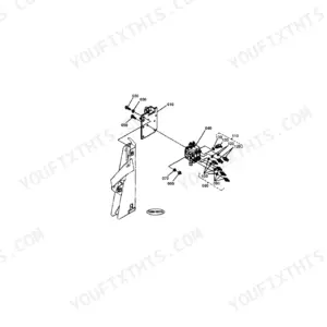
| Flange [Fp82-A] | 8-9 | Coupling Plate, Coupling Assy Shaft, Coupling Support, Grease Nipple, Collar |
| Front PTO | 10-12 | Front PTO Case, Seal Plate, Joint Shaft, Grease Nipple, Joint Cover, Pulley, Front Tension Arm, Tension Assy Pulley |
| Front PTO [Fp82-A] | 13-14 | Front PTO Case, Pulley, PTO Pulley, Front Tension Assy Arm, Bush, Tension Assy Pulley, Belt, Belt Retainer |
| Gear Box | 15-16 | Bevel Case, Roller Cap, Bevel Case Stay, Pinion Shaft, Bevel Gear, Oil Seal, Blank Order by, Assy Pulley |
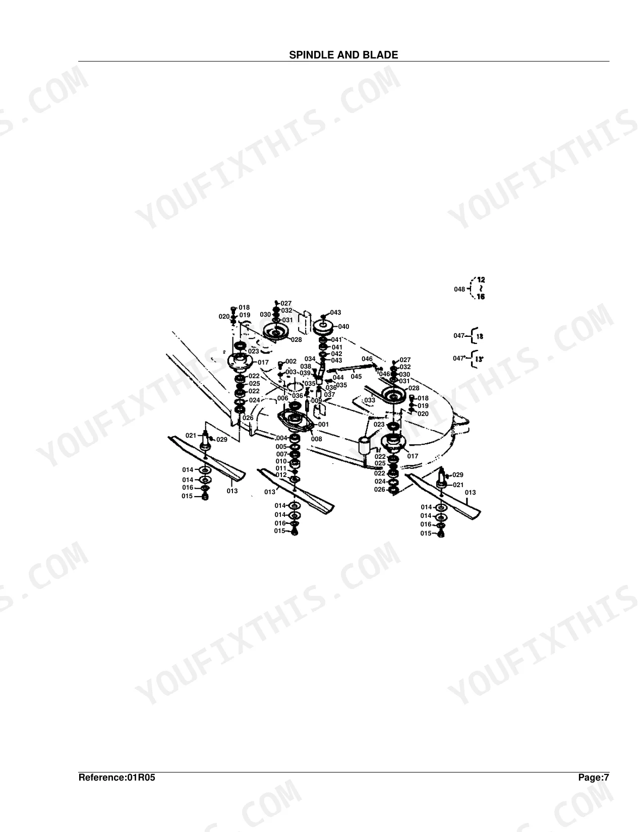
| Spindle and Blade | 17-19 | Pulley Holder, Oil Seal, Extension Pipe, Cutter Boss, Plate, Blade, Low Service Parts Blade, Retainer |
| Deck and Front Wheel | 20-21 | LH RCB60-I Assy Cover, Blank Order by, Seal, RH RCB60-I Assy Cover, Bearing Cap, Label RCB60-I, Label, Front Plate |
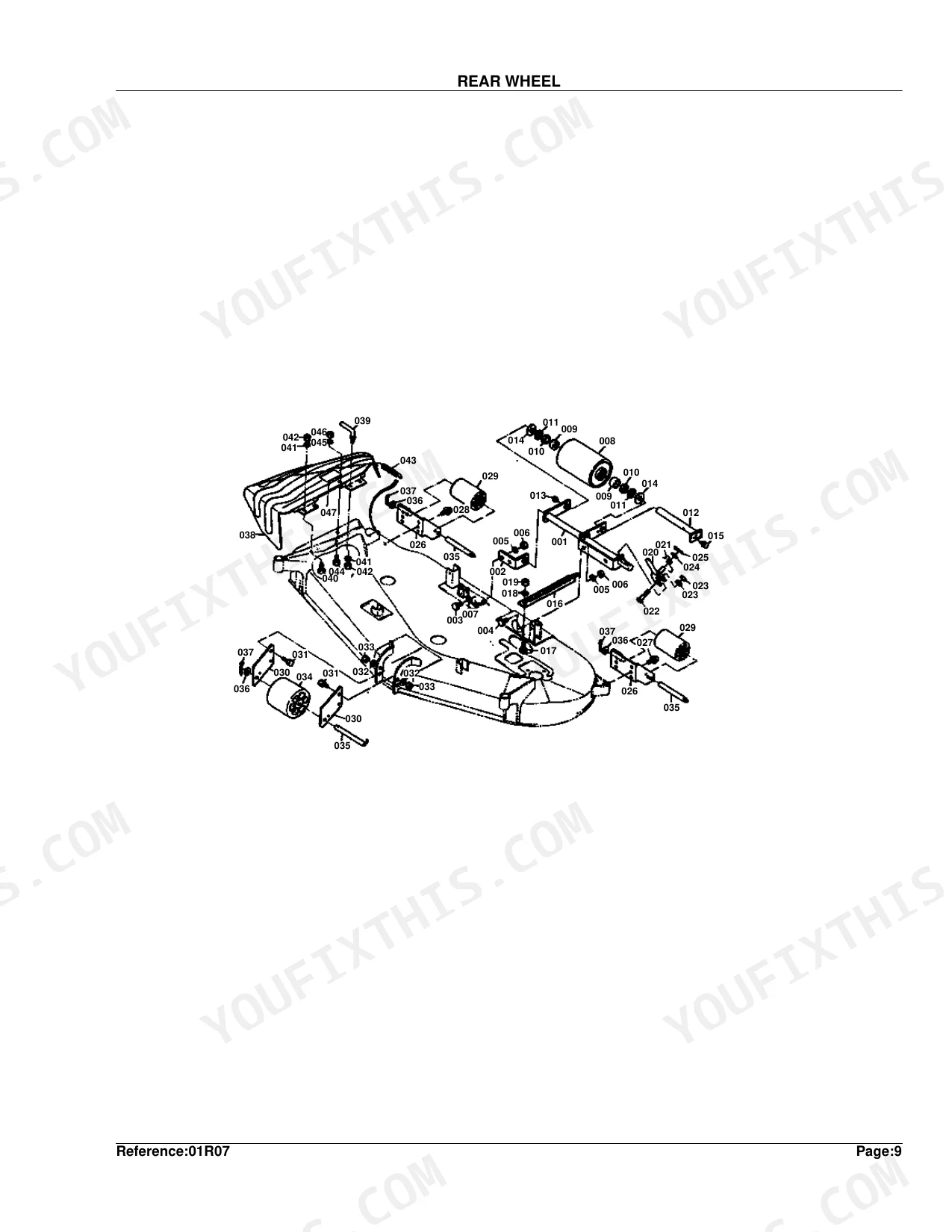
| Rear Wheel | 22-23 | Rear Wheel Arm, Rear Wheel Bracket, Rear RCB60-I Wheel, Bush, Oil Seal, Rear Wheel Shaft, Grease Nipple, Rear Wheel Guide |
| Main Stay | 24-25 | LH Front Stay, LH Rear Stay, RH Front Stay, RH Rear Stay, Lift Link Holder, Front Guide, LH Stay, RH Stay |
Quick Reference Specifications
| Specification | Value | Page |
|---|---|---|
| Weight of JOINT 1 (Part No. 70722-31110) | 1.73 kgf | p. 5 |
| Weight of FLANGE, PTO (Part No. 70722-32110, S.No. <=10250) | 0.515 kgf | p. 7 |
| Weight of NET, DUSTPROOF (Part No. 67800-86210) | 1.4 kgf | p. 7 |
| Weight of CASE, FRONT PTO (Part No. 70722-32313) | 6.6 kgf | p. 11 |
| Weight of PULLEY 117 (Part No. 70722-32370) | 1.41 kgf | p. 11 |
| Weight of BELT 40 (Part No. 70722-32430) | 0.175 kgf | p. 11 |
| Weight of CASE, BEVEL (Part No. 70722-33110) | 3.5 kgf | p. 16 |
| Weight of ASSY PULLEY, CENTER (Part No. 70722-99040, <=SEPT.1989) | 1.53 kgf | p. 16 |
| Weight of HOLDER, PULLEY 1 (Part No. 70722-34110) | 2.6 kgf | p. 18 |
| Weight of DECK, MOWER (Part No. 70722-41160, <=21015) | 74 kgf | p. 21 |
| Weight of WHEEL, FRONT (Part No. 70722-42110) | 1.9 kgf | p. 21 |
| Weight of STAY, LH FRONT (Part No. 70722-51110) | 4.2 kgf | p. 25 |
Kubota RCB60-I Common Problems This Manual Covers
Kubota RCB60-I deck drive belt needs replacement after storage, can't confirm correct part number before ordering
Check the Front PTO exploded view on page 10 to trace the full belt routing, then find BELT 40 listed as part number 70722-32430 (0.175 kgf) on page 11. Verify PULLEY 117 (part #70722-32370) shows no damage in that same diagram before ordering only the belt. If your unit carries the Fp82-A PTO configuration, cross-reference pages 13-14 for the alternate belt part number instead.
Manual Section: Front PTO p. 10Blade worn or chipped after long service, need correct cutter and spindle part numbers before ordering
Open the Spindle and Blade parts diagram on page 17 and locate your cutter shaft and blade positions in the exploded view. Match each one to the parts list on page 18, which lists HOLDER, PULLEY 1 at part number 70722-34110 (2.6 kgf). If the spindle shows play, note the retainer and bearing part numbers from that same list so the full assembly ships together.
Manual Section: Spindle and Blade p. 17Front anti-scalp wheel missing or cracked, cannot identify correct replacement part number
Turn to the Deck and Front Wheel section on page 20, where the exploded view breaks out the wheel, shaft, bearing, and cap as separate line items. WHEEL, FRONT appears on page 21 as part number 70722-42110 (1.9 kgf). If the shaft housing shows wear, note the bearing and cap part numbers from that same list, or you risk ordering the wheel and finding the bearing gone too.
Manual Section: Deck and Front Wheel p. 20Deck lift linkage bent or seized, need lift link and front stay part numbers for both sides
Start with the Main Stay parts diagram on page 24, which separates LH and RH front stays, lift link, guide, and holder into individual components. STAY, LH FRONT is part number 70722-51110 (4.2 kgf) on page 25. Pin down whether the damage is left-side, right-side, or the lift link itself before ordering, since all three are distinct line items with separate part numbers.
Manual Section: Main Stay p. 24Rear deck wheel or roller arm damaged, need rear wheel assembly part numbers to restore deck height control
Pull up the Rear Wheel diagram on page 22, where the arm, bracket, rear wheel, shaft, lever, stay, and roller appear as separate components. Find each worn part, note its index number, and match it to the parts list for the exact part numbers. If the arm geometry looks bent, order the stay and bracket along with the wheel, since mismatched components throw off deck height across the cutting width.
Manual Section: Rear Wheel p. 22PTO driveshaft joint worn or binding, need universal joint and cross assembly part numbers
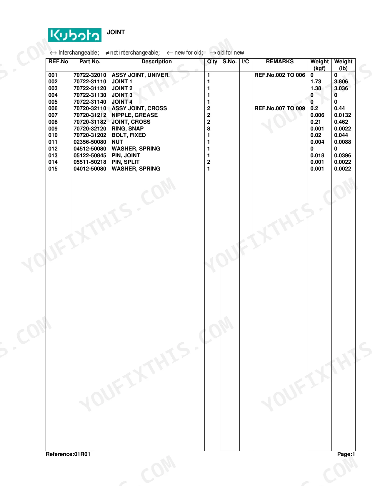
Check the Joint exploded view on page 4 against the parts list on page 5, where JOINT 1 is part number 70722-31110 (1.73 kgf). The diagram also breaks out the Assy Joint Cross, Grease Nipple, and Snap Ring as separate line items. Spot every worn component before ordering so the whole joint assembly goes in one order, not a return trip for the snap ring or nipple.
Manual Section: Joint p. 4Frequently Asked Questions
What are the replacement specifications for deck belt?
The deck belt is Part No. 70722-32430, listed as "BELT 40". Each one weighs 0.175 kgf (0.385 lb), and you need 2. p. 11
What are the replacement specifications for blades?
Three options exist. The standard "BLADE" is Part No. 70722-34330 at 0.99 kgf (2.178 lb) each, 3 required. "BLADE, LOW SUCTION" (Part No. 70722-99020) weighs 0.95 kgf (2.09 lb) each, also 3 required. Or order the "KIT BLADE", Part No. 70722-99650, at 3.5 kgf (7.7 lb). p. 18
What is the part number for the LH front stay on the Kubota RCB60-I?
Part No. 70722-51110 is the LH front stay, weighing 4.2 kgf. The parts list on page 25 separates left-side, right-side, and lift link components, so confirm which side is damaged before ordering. p. 25
Which part number covers the PTO driveshaft universal joint for the RCB60-I?
Part No. 70722-31110 is JOINT 1, weighing 1.73 kgf. The exploded view on page 4 also lists the cross assembly, grease nipple, and snap ring as separate line items, so order everything that shows wear in one shipment. p. 5
What is the front anti-scalp wheel part number for the Kubota RCB60-I?
WHEEL, FRONT is Part No. 70722-42110, weighing 1.9 kgf. Page 20 shows the shaft, bearing, and cap as separate line items; if the shaft housing shows wear, note those part numbers from the same list before ordering. p. 21
Is this Kubota RCB60-I Parts Catalog a digital download?
A 25-page Parts Catalog in searchable PDF format, available the moment checkout finishes. Open it on a computer, tablet, or phone, with no shipping wait.
Is this Kubota RCB60-I Parts Catalog printable?
Yes. Print as many copies as you want; there are no restrictions. Plenty of mechanics print just the section they need and carry it to the shop floor.


Reviews
There are no reviews yet.