
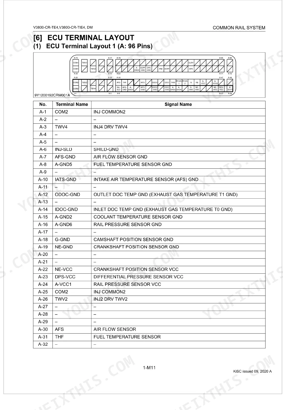


This Kubota V3800-CR-TE4 / V3800-CR-TIE4 Diagnostic Manual (OEM #9Y110-01922) has one job across its 349 pages: pinpointing common rail fuel faults on M60, M-GX, M5001 Utility Narrow, and M5-AUS series tractors. Wiring diagrams map both ECU connectors (96-pin A, 58-pin B) down to the terminal, with full pin-outs alongside. DTC coverage runs past 58 pages, from NE/G phase shift (P0016/636-7) through pressure limiter and MAF sensor faults, and another 55 pages track symptoms one at a time: hard starts, idle instability, the engine warning light, high fuel consumption. Confirm injectors fall within 0.35–0.55 Ω, check that warm idle holds 800 rpm, and read boost at 100 kPa. With the engine down and the clock running, open it on any device, search by DTC or symptom, and get the factory answer.
What's Inside This Kubota V3800-CR-TE4, V3800-CR-TIE4 Manual
| System | Pages | Key Topics |
|---|---|---|
| Information | 3-7 | Contents, Safety First, Danger, Warning, Caution, Important, Note, Before Servicing And Repairing |
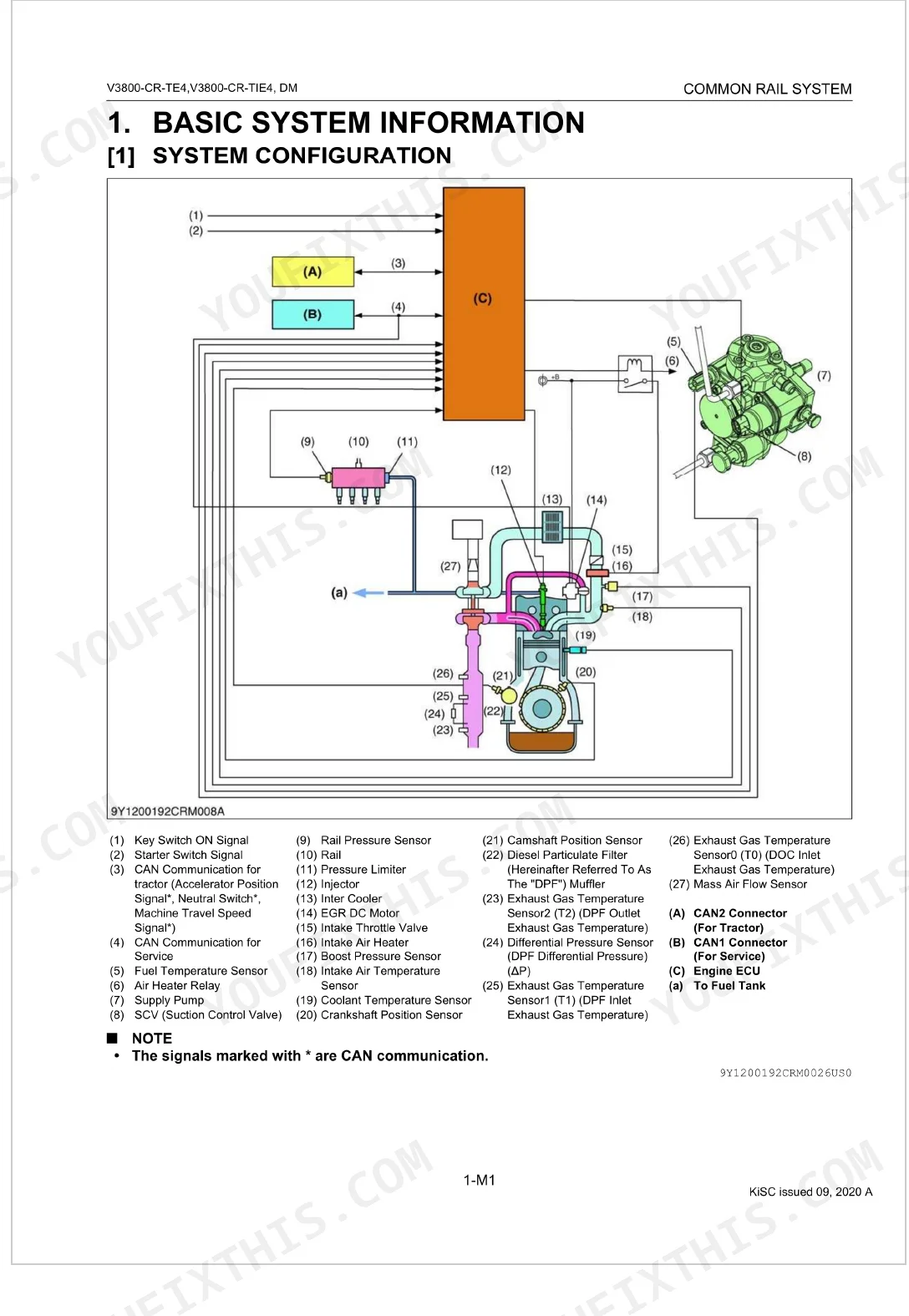
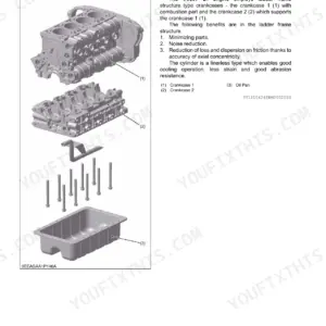
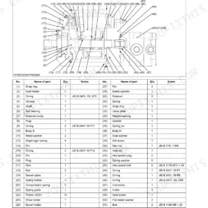
| Common Rail System | 8-28 | Mechanism |
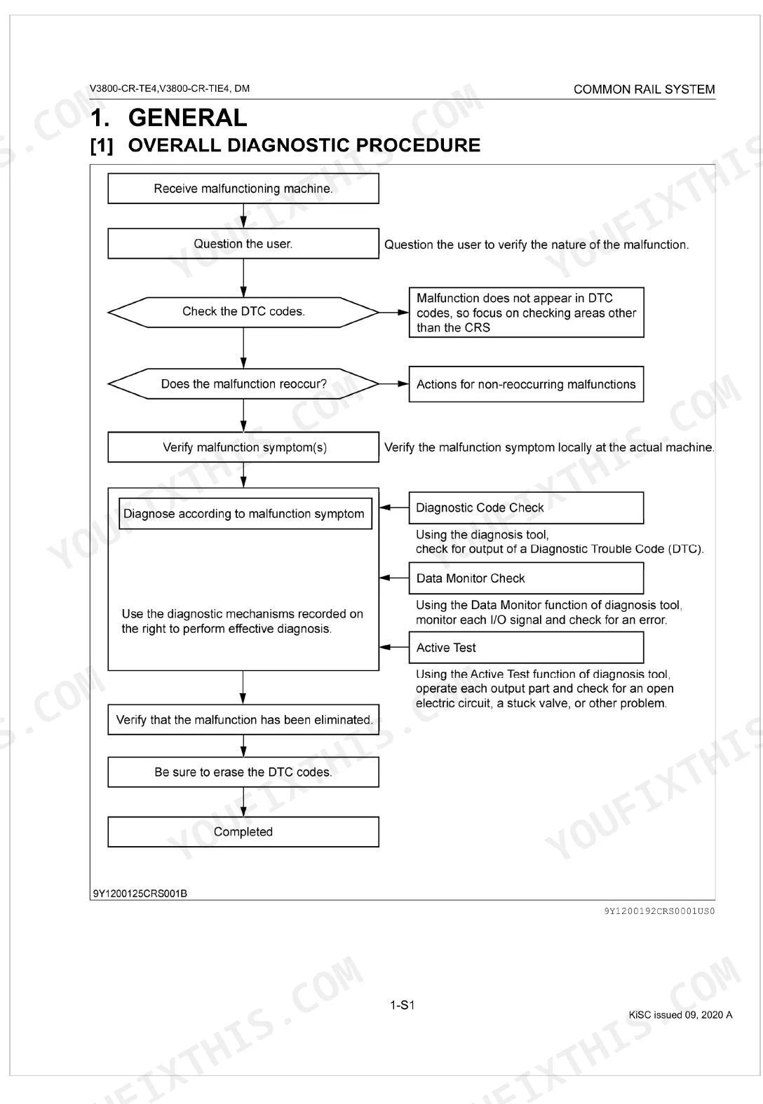
| General | 29-35 | Overall Diagnostic Procedure, Questioning, List of Malfunction Symptom, Actions for Non-Reoccurring Malfunctions |
| Diagnostic Tool Connection Procedure | 36-44 | Diagnostic Connector Positions, Checking Communication Operation of Interface (DST-i), Checking Operation of ECU |
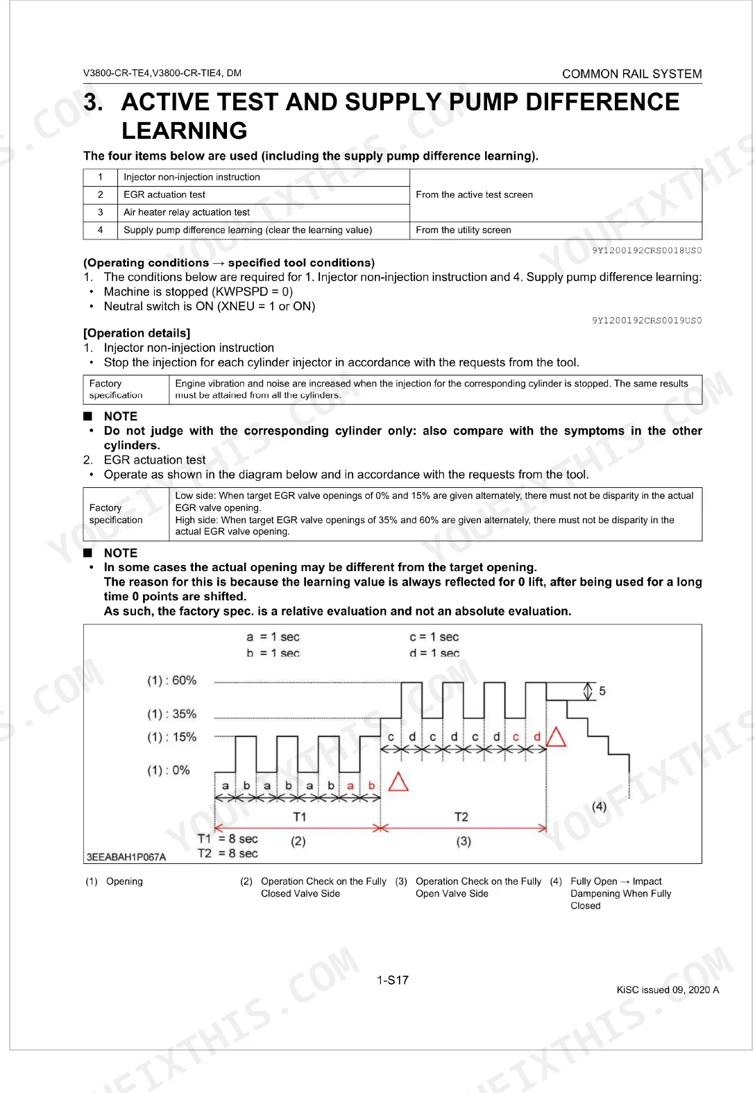
| Active Test and Supply Pump Difference Learning | 45-46 | Injector Non-Injection Instruction, EGR Actuation Test, Air Heater Relay Actuation Test, Supply Pump Difference Learning |
| Diagnosis by Malfunction Symptom | 47-104 | List of Malfunction Causes by Symptom, Engine Warning Light Comes On, Takes A Long Time Before Engine Starts, Idle Failure, Engine Noise, High Fuel Consumption |
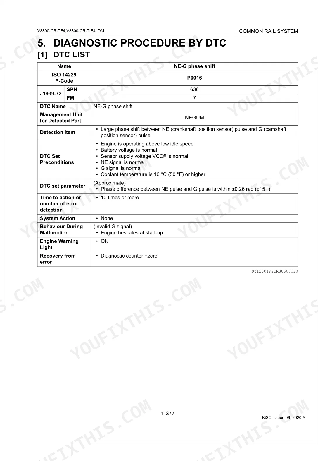
| Diagnostic Procedure by DTC | 105-299 | DTC List, NE - G Phase Shift (DTC P0016 / 636-7), Intake Air Temperature Built-in MAF Sensor Abnormality, Pressure Limiter Emergency Open (DTC P0087 / 633-7) |
| Inspection Procedure for Each System | 300-349 | Air Intake System Inspection Procedure, Fuel System Inspection Procedure, Electric System Inspection Procedure (Basics Of Checking Electrical / Electronic Circuit Systems) |
Quick Reference Specifications
| Specification | Value | Page |
|---|---|---|
| Injector resistance | 0.35 to 0.55 Ω | p. 95 |
| NE Sensor Pull-up Resistor | 1 kΩ | p. 108 |
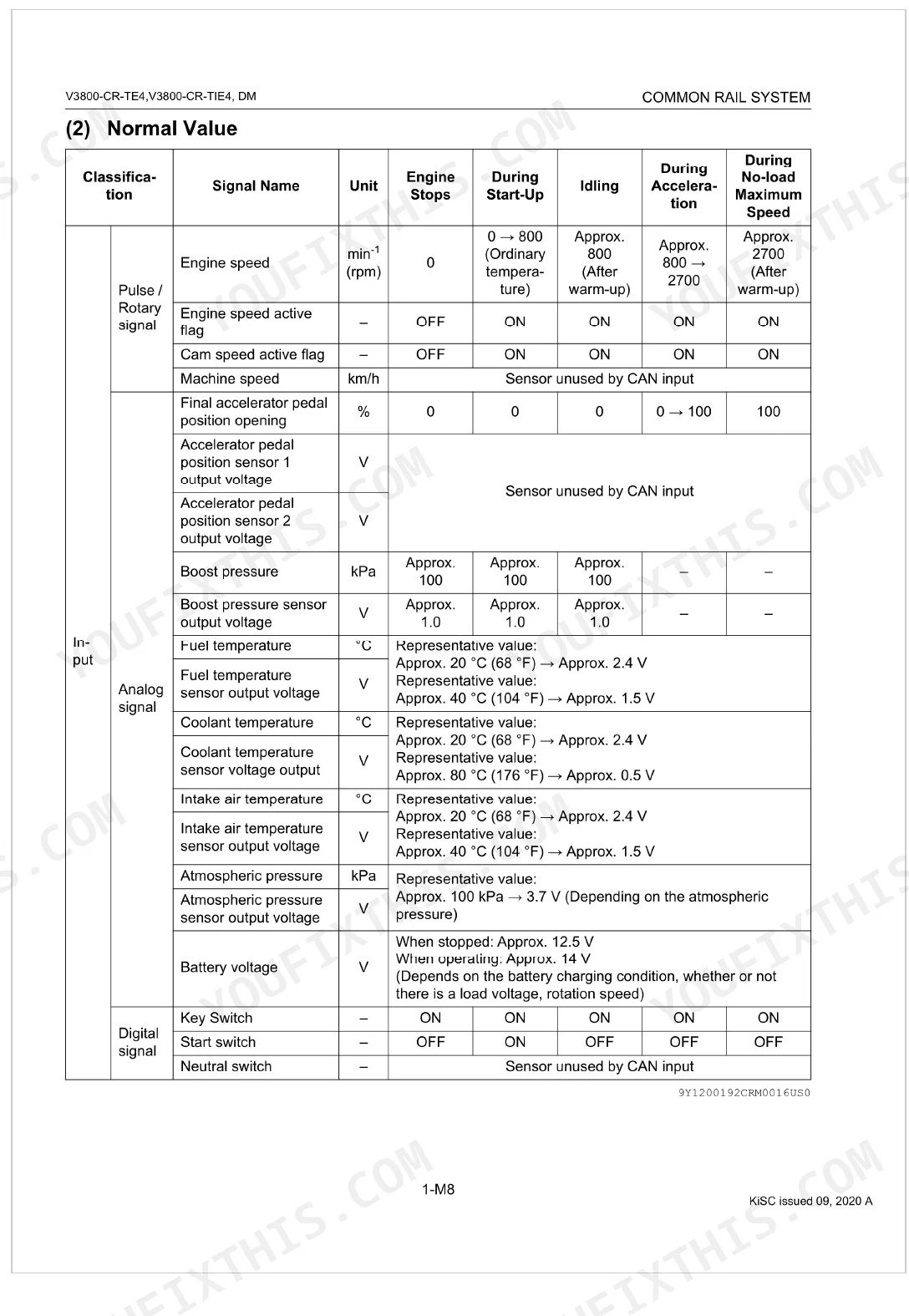
| Engine speed (Idling, after warm-up) | 800 min⁻¹ (rpm) | p. 17 |
| Engine speed (No-load Maximum Speed, after warm-up) | 2700 min⁻¹ (rpm) | p. 17 |
| Boost pressure (Approx.) | 100 kPa | p. 17 |
| Boost pressure sensor output voltage (Approx.) | 1.0 V | p. 17 |
| Battery voltage (When stopped) | 12.5 V | p. 17 |
| Battery voltage (When operating) | 14 V | p. 17 |
| Target rail pressure (Idling) | 40 to 50 MPa | p. 18 |
| Target rail pressure (No-load maximum speed) | 95.0 to 115 MPa | p. 18 |
| Target rail pressure (Acceleration) | 95.0 to 130 MPa | p. 18 |
| Rail pressure sensor output voltage (When stopped) | 1.0 V | p. 18 |
Kubota V3800-CR-TE4, V3800-CR-TIE4 Common Problems This Manual Covers
Kubota V3800-CR-TIE4 DTC P0016 stored, NE-G phase shift fault, engine cranks but won't start p. 105
Connect diagnostic tool per page 36, then retrieve DTC P0016 from the ECM. Inspect the NE sensor circuit: the pull-up resistor should read 1 kΩ at the ECM connector per page 108. Confirm G sensor signal alignment with the crankshaft reference, and check harness routing between sensors for chafing or corrosion per the circuit diagram on page 13.
Manual Section: Diagnostic Procedure by DTCRail pressure sensor voltage out of spec at idle, engine warning light illuminated, power reduced p. 47
Verify rail pressure sensor output voltage at idle reads 1.65 to 1.80 V (page 18). With key on and engine off, confirm the sensor reads 1.0 V. Missing or erratic voltage points to the sensor connector or harness; check for shorts using the pinout diagram on page 20. Cross-reference the DTC list on page 105 for associated stored fault codes.
Manual Section: Diagnosis by Malfunction SymptomInjector resistance out of spec DTC active, rough idle or cylinder misfire logged p. 105
Measure injector coil resistance across each injector connector; spec is 0.35 to 0.55 Ω per page 95. Readings outside that range indicate a failed injector or damaged wiring. Run the injector non-injection instruction active test on page 45 to isolate the suspect cylinder before condemning the injector.
Manual Section: Diagnostic Procedure by DTCBoost pressure sensor output voltage incorrect, underboost DTC stored after heavy load p. 105
Check boost pressure sensor output voltage with key on and engine running: expect roughly 1.0 V at idle boost of 100 kPa per page 17. Voltage that is absent or stuck points to the sensor wiring at the ECM harness; trace it using the pinout on page 20. Run the overall diagnostic procedure on page 29 to confirm no related DTCs are active.
Manual Section: Diagnostic Procedure by DTCPoor acceleration and insufficient output at load, no DTC stored, fuel quality suspect p. 47
Start with fuel quality: confirm cetane rating meets minimum 45 per page 303. Check fuel filter efficiency: spec requires 5 µm at 95% dust-collecting efficiency or better (page 304). Inspect rail pressure at no-load maximum speed; target is 95.0 to 115 MPa (page 18). If pressure drops under acceleration demand, follow the poor acceleration symptom diagnostic tree in the section starting at page 47.
Manual Section: Diagnosis by Malfunction SymptomEngine warning light comes on intermittently, no active DTC found at time of inspection p. 29
Follow the non-reoccurring malfunction procedure starting at page 29. Connect the DST-i diagnostic tool per page 36 and verify ECU communication. Battery voltage should read 12.5 V at rest and 14 V while charging (page 17). Review freeze-frame data in the DTC history on page 105 to reconstruct operating conditions when the warning triggered.
Manual Section: GeneralFrequently Asked Questions
What are the recommended service intervals?
Service intervals vary by component. The air cleaner element should be cleaned every 250 hours, or after every sixth cleaning, whichever comes first. The fuel filter should be replaced every 500 hours.
What fluids and capacities does this machine require?
No.2-D diesel is required, with a recommended cetane rating of 45. For ultra-low-sulfur diesel, the spec calls for No.1-D or No.2-D at 15 ppm (0.0015 wt.%) sulfur. Biodiesel (BDF) is acceptable but can deteriorate from oxygen, water, heat, and other foreign substances.
How to troubleshoot engine won't start?
Start by checking fuel feed pump operation, then read any Diagnostic Trouble Codes (DTCs). Next, inspect the starting assist device and the intake system. From there, work through the fuel system, ECU power supply and grounding, crankshaft and camshaft position sensor signals, and supply pump difference learning, all detailed from page 51 onward.
How to reset error codes or warning lights?
Most Diagnostic Trouble Codes (DTCs) clear when you turn the key switch OFF. For some, the diagnostic counter resets to zero on recovery. The overall diagnostic procedure also says to "Be sure to erase the DTC codes," which points to an erase function in the diagnostic tool.
What do I get after purchasing this Kubota V3800-CR-TE4, V3800-CR-TIE4 manual?
A 349-page Diagnostic Manual in searchable PDF, available the moment you complete checkout. View it on a computer, tablet, or phone, with no shipping wait.
Are there any print restrictions on this Kubota V3800-CR-TE4, V3800-CR-TIE4?
No restrictions at all. Print individual pages, full chapters, or the entire manual. The PDF is completely unlocked.
Can I find wiring schematics in this Kubota V3800-CR-TE4, V3800-CR-TIE4 manual?
Yes. You'll find full electrical schematics with wire routing diagrams, connector identification, and circuit descriptions.
Document Quality
This document is a scanned PDF with an OCR layer, allowing you to search and copy the full text content. The text quality is consistently crisp and easy to read across all pages, with no blurry or faded sections. Diagrams and illustrations, including detailed wiring diagrams and component layouts, are clear raster images, and all labels are sharp and perfectly readable. The pages themselves are clean, completely free from scan artifacts, stains, marks, or skewed content. You will find no notable blank or filler pages within this manual.

Reviews
There are no reviews yet.