Part of the Kubota Repair Manuals.
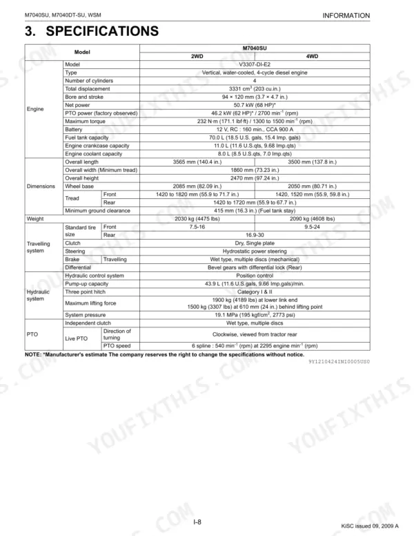
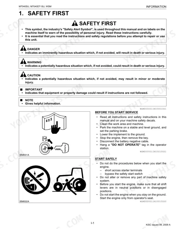
This Kubota Workshop Manual covers the M7040SU and M7040DT-SU utility tractors, both built around the V3307-DI-E2 diesel engine. It is the factory service documentation, running 407 pages across eleven sections that move from safety and specifications through the engine, clutch, transmission, axles, brakes, steering, hydraulics, and the full electrical system.
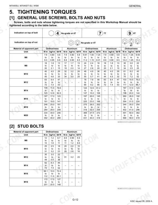
With it you can work to Kubota's own figures: valve clearance of 0.13 to 0.17 mm, engine compression at 3.92 MPa, hydraulic system pressure of 19.1 MPa, and fluid capacities such as the 70.0 L fuel tank and 44.0 L transmission case. Torque tables, maintenance intervals, wiring diagrams, and step by step disassembly procedures let an owner or independent mechanic diagnose faults, rebuild components, and service the tractor correctly rather than guessing.
Delivered as a downloadable PDF you can search, print, and keep on any device.
What's Inside This Manual
| System | Pages | Key Topics |
|---|---|---|
| I Information | 3-14 | |
| G General | 15-97 | Tractor Identification, General Precautions, Electrical Parts and Wiring, Lubricants, Fuel and Coolant, Tightening Torques |
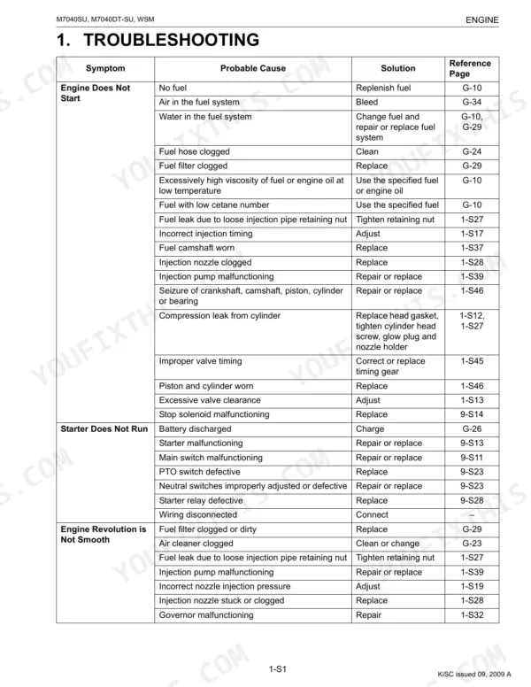
| Engine | 98-185 | Engine Body, Lubricating System, Cooling System, Fuel System |
| Clutch | 186-216 | Travelling Clutch, PTO Clutch, PTO Clutch Valve |
| Transmission | 217-258 | Structure, Traveling System, PTO System, Lubrication for Transmission |
| Rear Axle | 259-271 | Separating Rear Axle Case, Disassembling Planetary Gear, Disassembling Rear Axle, Servicing |
| Brakes | 272-283 | Structure, Brake Pedal, Brake Case, Brake Disc and Plate |
| Front Axle | 284-310 | Structure, Servicing Specifications, Checking and Adjusting, Disassembling and Assembling, Servicing |
| Steering | 311-330 | Steering Controller, Power Steering Hydraulic Pump, Steering Cylinder, Relief Valve, Tie-Rod, Gerotor |
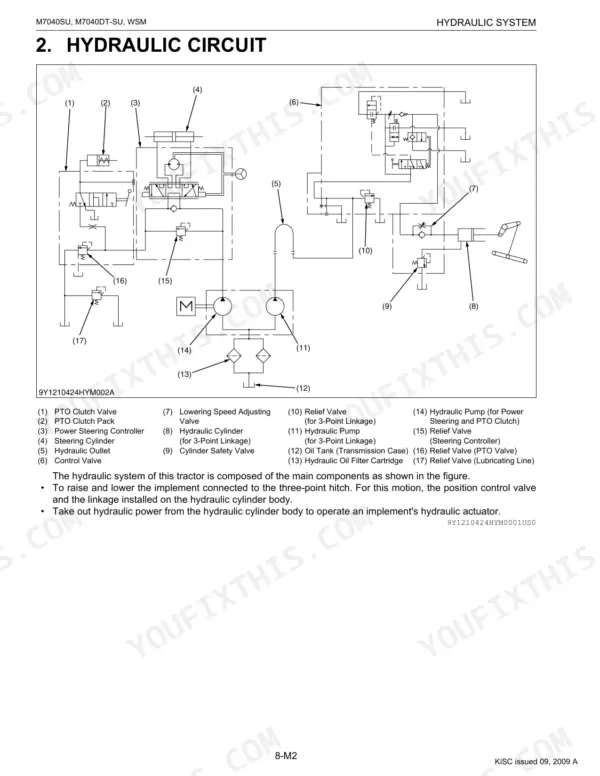
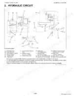
| Hydraulic System | 331-357 | Hydraulic Pump, Hydraulic Circuit, Hydraulic Block, Relief Valve, Safety Valve, Position Control Linkage, Hydraulic Cylinder |
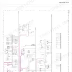
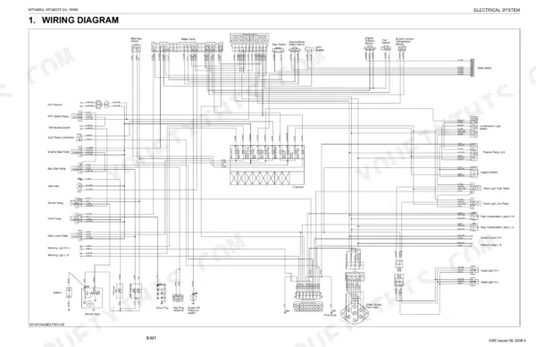
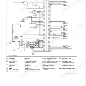
| Electrical System | 358-407 | Wiring Diagram, Electrical Circuit Detailed Chart, Starting System, Charging System, Lighting System, Flasher Unit, Instrument Panel, Lcd Monitor |
Documents This Manual Refers To
The manufacturer cites these publications by number. We carry them:
Quick Reference Specifications
| Specification | Value | Page |
|---|---|---|
| All Models | ||
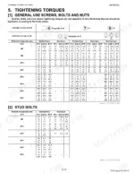
| General Use Screws, Bolts and Nuts (M10, Ordinariness, No-grade or 4T) | 40 to 45 N·m (4.0 to 4.6 kgf·m, 29 to 33 lbf·ft) | p. 28 |
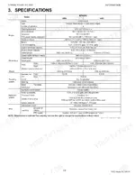
| Fuel tank capacity | 70.0 L (18.5 U.S. gals, 15.4 Imp. gals) | p. 26 |
| Engine crankcase capacity (with filter) | 11.0 L (11.6 U.S.qts, 9.68 Imp.qts) | p. 26 |
| Maintenance Service Intervals | Detailed table with intervals including: every 50 Hr, every 100 Hr, every 200 Hr, every 300 Hr, every 400 Hr, every 600 Hr, every 800 Hr, every 1500 Hr, every 3000 Hr, every 1 year, every 2 years, Service as required. | p. 30 |
| M7040SU | ||
| Engine Total Displacement | 3331 cm3 | p. 12 |
| Fuel Tank Capacity | 70.0 L | p. 12 |
| Engine Oil Capacity (with filter) | 11.0 L | p. 12 |
| Transmission Fluid Capacity | 44.0 L | p. 26 |
| Engine Compression Pressure (Factory Spec) | 3.92 MPa / 250 min-1 (rpm) | p. 118 |
| Engine Valve Clearance (Cold, Factory Spec) | 0.13 to 0.17 mm | p. 118 |
| Alternator Belt Tension (Factory Spec) | 10.0 to 12.0 mm | p. 122 |
| M7040SUD | ||
| Front Differential Gear Case Capacity | 6.6 L | p. 26 |