

This Kubota Service Manual documents the ZD1211-AU, ZD1221R-AU, ZD1221L-AU, and ZD1221RL-AU zero-turn mowers, powered by the D1105 and D1305 diesel engines. It is the factory workshop documentation across 294 pages, split into mechanism and servicing sections for the engine, hydrostatic transaxle, front axle, hydraulic system, electrical system, and the mower deck itself.
The manual gives Kubota's own service figures, including valve clearance of 0.145 to 0.185 mm, compression of 3.73 to 4.11 MPa, a 49 L fuel tank, and mower blade screw torque of 102.9 to 117.6 N·m. Troubleshooting charts, tightening torques, maintenance intervals, and wiring diagrams let an owner or mechanic diagnose HST weakness, adjust the deck, rebuild the engine, and keep the machine serviced to specification.
It downloads as a searchable, printable PDF you can keep on any device.
What's Inside This Manual
| System | Pages | Key Topics |
|---|---|---|
| Record of Revisions | 3 | Last Digit of the Code No., Month of Revision, Main Revised Point and Corrective Measures |
| Information | 4-17 | |
| General | 18-75 | Identification, Cylinder Nymber, Handling Precautions for Electrical Parts and Wiring (Battery, Fuse, Connector, Handling of Circuit Tester, Color of Wiring), Lubricants |
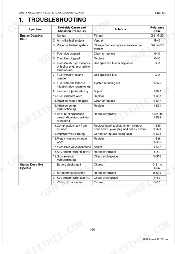
| Engine Mechanism | 76-83 | Engine Body (Closed Breather, Governor), Lubricating System, Cooling System, Fuel System |
| Engine Servicing | 84-140 | Servicing Specifications (D1105-E4, D1305-E3), Separating Engine |
| Transaxle Mechanism | 141-153 | Structure, Travelling System (Hydrostatic Transmission), PTO System, Parking Brake |
| Transaxle Servicing | 154-196 | Separating Transaxle Assembly, Disassembling Transaxle Center Case, Disassembling PTO Clutch Shaft Assembly, Disassembling Rear Axle Gear Case, Disassembling Speed Lever Assembly, Hydrostatic Transmission, Transmission Case, PTO Clutch |
| Front Axle Mechanism | 197-199 | Structure, Front Axle Construction, Component Identification |
| Front Axle Servicing | 200-206 | Front Axle, Front Wheel, Wheel Bracket, Center Pin, Connecting Plate, Battery, Step, Step Center |
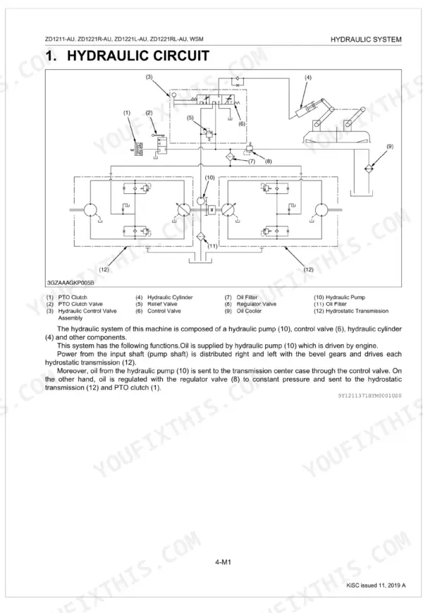
| Hydraulic System Mechanism | 207-214 | Hydraulic Circuit, Hydraulic Pump, Hydraulic Control Valve, Lift Cylinder |
| Hydraulic System Servicing | 215-227 | Hydraulic Control Valve, Pump and Cylinder |
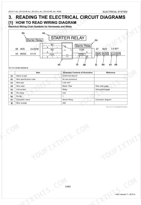
| Electrical System Mechanism | 228-248 | Electrical Diagram, Electrical Connector Chart |
| Electrical System Servicing | 249-270 | Battery, Safety Switches, Main Switch, Starter, Glow Plug, Fuel Pump, Engine Stop Solenoid, Charging System |
| Mower Mechanism | 271-274 | Power Transmission, Mower Linkage (Center Blade, Outer Blade, Lifting Mechanism, Cutting Height Adjustment), Safety Precautions |
| Mower Servicing | 275-294 | Anti-Scalp Rollers, Cutting Height, Lifting Linkage, Dial Cam Gear, Mower Linkage, Mower Deck, Universal Joint and Belt Covers, Mower Blades |
Documents This Manual Refers To
The manufacturer cites these publications by number. We carry them:
Quick Reference Specifications
| Specification | Value | Page |
|---|---|---|
| All Models | ||
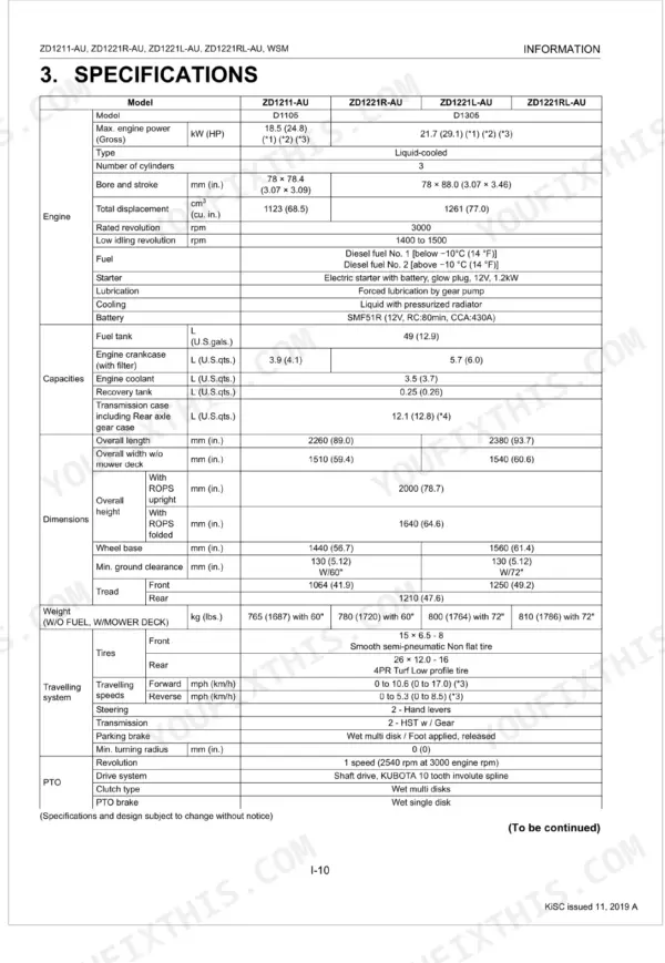
| Fuel tank capacity | 49 L (12.9 U.S.gals.) | p. 28 |
| Coolant capacity | 3.5 L (3.70 U.S.qts.) | p. 28 |
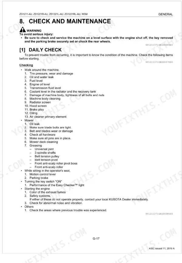
| Engine start system check | every 50 Hr | p. 33 |
| OPC system check | every 50 Hr | p. 33 |
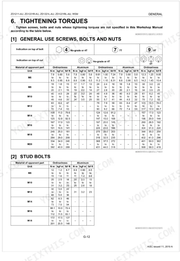
| M6 (No-grade or 4T) General Use Screws, Bolts and Nuts | 7.9 to 9.3 N-m | p. 31 |
| M6 (7T) General Use Screws, Bolts and Nuts | 9.81 to 11.2 N-m | p. 31 |
| Valve Clearance (Cold) | 0.145 to 0.185 mm | p. 88 |
| Compression Pressure (Factory Specification) | 3.73 to 4.11 MPa | p. 88 |
| Engine Oil Pressure (At Rated Speed, Factory Specification) | 294 to 441 kPa | p. 92 |
| Fan Belt Tension (Deflection) | 7.0 to 9.0 mm | p. 97 |
| ZD1211-AU | ||
| Engine Oil Capacity, ZD1211-AU | 3.9 L (4.1 U.S.qts) | p. 28 |
| ZD1221R-AU, ZD1221L-AU, ZD1221RL-AU | ||
| Engine Oil Capacity (ZD1221R-AU, ZD1221L-AU, ZD1221RL-AU) | 5.7 L (6.0 U.S.qts) | p. 28 |