Part of the Kubota Repair Manuals.
This Kubota Diagnostic Manual covers the V3800-CR-TE4 and V3800-CR-TIE4 common rail diesel engines used in tractors, across 349 pages focused on fault-finding rather than teardown.
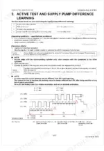
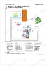
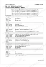
It explains the common rail fuel system and its mechanism, then walks through diagnosis by malfunction symptom and diagnosis by diagnostic trouble code (DTC), with a large DTC-by-code procedure section. You also get diagnostic tool connection for the DST-i interface and Diagmaster, active tests and supply pump difference learning, and inspection procedures for the air intake, fuel, and electrical systems.
The manual downloads as a searchable, bookmarked PDF, so you can jump straight to a symptom, a DTC, or a system inspection on a phone, tablet, or shop computer and print only the pages a diagnosis needs.
What's Inside This Manual
| System | Pages | Key Topics |
|---|---|---|
| Information | 3-7 | Contents, Safety First, Danger, Warning, Caution, Important, Note, Before Servicing and Repairing |
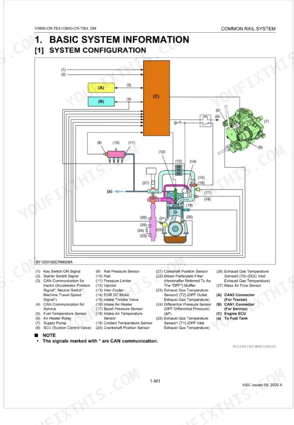
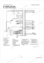
| Common Rail System | 8-28 | Basic System Information, System Configuration, Fuel System, Intake And Exhaust System, Wiring Diagram, System Wiring Diagram, Available Data Monitor Signals (Level 2), Monitor Items |
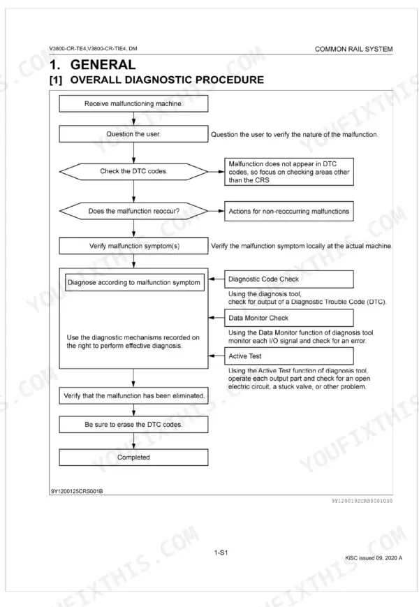
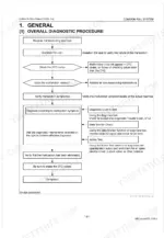
| General | 29-35 | Overall Diagnostic Procedure, Questioning, List of Malfunction Symptom, Actions for Non-Reoccurring Malfunctions |
| Diagnostic Tool Connection Procedure | 36-44 | Diagnostic Connector Positions, Checking Communication Operation of Interface (DST-i), Checking Operation of ECU |
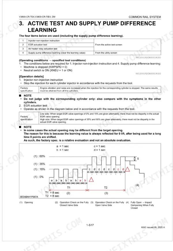
| Active Test and Supply Pump Difference Learning | 45-46 | Injector Non-Injection Instruction, EGR Actuation Test, Air Heater Relay Actuation Test, Supply Pump Difference Learning |
| Diagnosis by Malfunction Symptom | 47-104 | List of Malfunction Causes by Symptom, Engine Warning Light Comes on, Takes a Long Time Before Engine Starts, Idle Failure, Engine Noise, High Fuel Consumption |
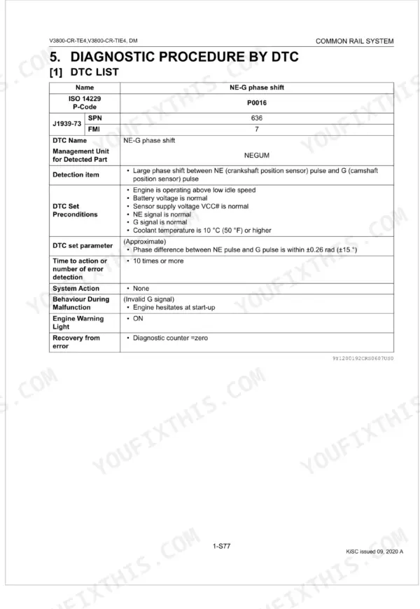
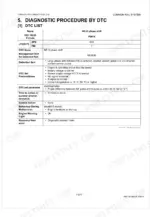
| Diagnostic Procedure by Dtc | 105-299 | Dtc List, Ne - G Phase Shift (Dtc P0016 / 636-7), Intake Air Temperature Built-In Maf Sensor Abnormality, Pressure Limiter Emergency Open (Dtc P0087 / 633-7) |
| Inspection Procedure for Each System | 300-349 | Air Intake System Inspection Procedure, Fuel System Inspection Procedure, Electric System Inspection Procedure (Basics of Checking Electrical / Electronic Circuit Systems) |
Quick Reference Specifications
| Specification | Value | Page |
|---|---|---|
| Injector resistance | 0.35 to 0.55 Ω | p. 213 |
| NE Sensor Pull-up Resistor | 1 kΩ | p. 108 |
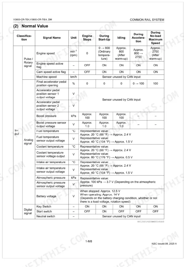
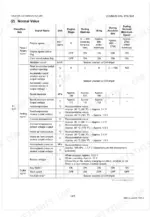
| Engine speed (Idling, after warm-up) | 800 min⁻¹ (rpm) | p. 17 |
| Engine speed (No-load Maximum Speed, after warm-up) | 2700 min⁻¹ (rpm) | p. 17 |
| Boost pressure (Approx.) | 100 kPa | p. 17 |
| Boost pressure sensor output voltage (Approx.) | 1.0 V | p. 17 |
| Battery voltage (When stopped) | 12.5 V | p. 17 |
| Battery voltage (When operating) | 14 V | p. 17 |
| Target rail pressure (Idling) | 40 to 50 MPa | p. 18 |
| Target rail pressure (No-load maximum speed) | 95.0 to 115 MPa | p. 18 |
| Target rail pressure (Acceleration) | 95.0 to 130 MPa | p. 18 |
| Rail pressure sensor output voltage (When stopped) | 1.0 V | p. 18 |