


This is the factory service manual for the Mustang 2056 skid-steer loader, powered by the turbocharged Deutz TD2009L04 diesel engine and produced from 2011 to 2016. The 221 page manual, part number 917438, covers specifications, safety procedures, the lubrication system, mainframe, wheel drives, controls, the hydraulic and hydrostatic systems, engine, and electrical system.Owners and independent mechanics can use it to troubleshoot starting and hydraulic faults, test charge and system pressures, service the lift and tilt cylinders, adjust the drive chain, work on the axle housings, and set correct torque on wheel nuts and cylinder locknuts. Detailed schematics and photographs support the procedures.The download is a searchable PDF that opens on any device, and you can print whichever pages you need for the workshop.
What's Inside This Mustang 2056 Manual
| System | Pages | Key Topics |
|---|---|---|
| Visual Hydraulic Oil Level Indicator | 18 | - |
| Hydraulic Oil Drain | 19 | General Information, Hydraulic Oil Reservoir |
| Hydraulic Filter Indicator | 19 | General Information, Hydraulic Oil Reservoir |
| Hydraulic Oil Fill Cap | 19 | General Information, Hydraulic Oil Reservoir |
| Engine Oil Dipstick | 19 | Introduction, Troubleshooting Guide, Engine Components, Air Cleaner and Exhaust Components, Radiator/Cooler Components, Remote Oil Filter Element Removal and Installation |
| Engine Oil Fill | 20 | Introduction, Troubleshooting Guide, Engine Components, Air Cleaner and Exhaust Components, Radiator/Cooler Components, Remote Oil Filter Element Removal and Installation |
| Remote Engine Oil Drain | 20 | Introduction, Troubleshooting Guide, Engine Components, Air Cleaner and Exhaust Components, Radiator/Cooler Components, Remote Oil Filter Element Removal and Installation |
| Remote Engine Oil Filter | 20 | Introduction, Troubleshooting Guide, Engine Components, Air Cleaner and Exhaust Components, Radiator/Cooler Components, Remote Oil Filter Element Removal and Installation |
| Chaincase Drain Plug | 20 | - |
| Chaincase Fill Plug | 21 | Chaincases, Change Chaincase Oil |
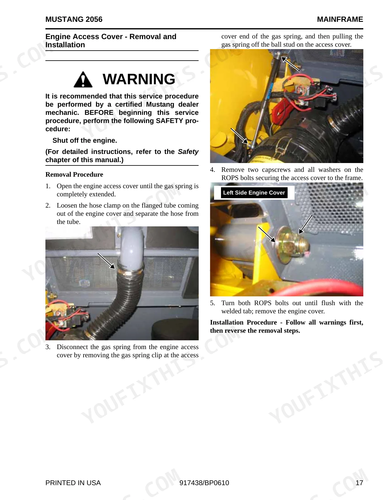
| Anti-Freeze Drain Cock | 22-41 | Grease Fitting Locations, Cooling System Drain Procedure, Radiator Drain Procedure, Hydraulic Oil Cooler Plug/Cap Procedure, Introduction, Mainframe (Chassis) Components, Rear Grille and Engine Cover Components, Removal Procedure |
| Neutral Centering Device Adjustment - Dual Hand and Hand/Foot Controls | 43-78 | Axle and Wheel Bearing Disassembly and Assembly, Rear Grille Latch Removal and Installation, Crossmember Removal and Installation, Installation Procedure, Removal Procedure, Fuel Sensor Removal and Installation, Rear Grille Removal and Installation, Drive Chain Removal and Installation |
| Charge Pressure Test and Adjustment | 79-109 | Auxiliary Hydraulics Cable Removal and Installation - Dual Hand and Hand/Foot Controls, Lift/Tilt Controls Removal and Installation, Pump Control Arm Assembly Removal and Installation, Neutral Centering Adjustment - Dual Joystick Controls, Adjustment Procedure, Removal Procedure, Installation Procedure, Removal Procedure - Hand/Foot Controls |
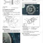
| High-Flow Auxiliary - Dual Joystick Controls | 110-125 | Drive Motor Removal and Installation, Hydrostatic Pump Drive Coupling Removal and Installation, Hydrostatic Pump Removal / Installation, Hydrostatic/Hydraulic Schematic - Dual Joystick Controls, Hydrostatic/Hydraulic Schematic - Non-Dual Joystick Controls, Introduction, Troubleshooting Guide |
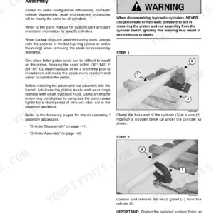
| Manifold Valve Removal and Installation | 126-141 | Lift Cylinder Test, Chassis Hydraulics, Hydraulic Oil Filter Element Replacement, High-Flow Auxiliary - Dual Hand and Hand/Foot Controls, Solenoid Valve Test - Tilt, Lift, Brake and Two-Speed, Test Procedure |
| Master Fuse Test | 142-160 | Manifold Valve Removal and Installation, Hydraglide™ Ride Control Hydraulics, Main Relief Valve Removal and Installation, Control Valve Disassembly and Assembly, Gear Pump Removal and Installation, Installation Procedure, Disassembly Procedure, Self-Leveling Valve Removal and Installation |
| Electrically-Controlled High-Flow Auxiliary Hydraulic Flow System Test and Operation | 161-176 | Control Handle Actuation Buttons - Two-Speed and Ride Control and Float Module, Interlock Control Module Test, Glow Control Module Test, Iso Spdt Interlock, Joystick, EGR, Fuel and Horn Relays Test |
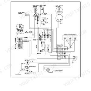
| Air Filter Element Removal and Installation | 177-192 | Heater Schematic, ROPS/FOPS - Electrical Schematic, 2-Bank and 4-Bank Coil Function Colored Wire Connector Chart, Auxiliary Neutral Start Switch, Traction Solenoid Test and Operation, Chassis - Electrical Schematic, Electrical Auxiliary Schematic, Engine - Electrical Schematic |
| Engine Removal and Installation | 193-221 | Radiator/ Oil Cooler Removal and Installation, Starter Removal and Installation, Battery and Battery Tray Removal and Installation, Removal Procedure, Installation Procedure, Exhaust Assembly Removal and Installation, Fan Belt Adjustment, Adjustment Procedure |
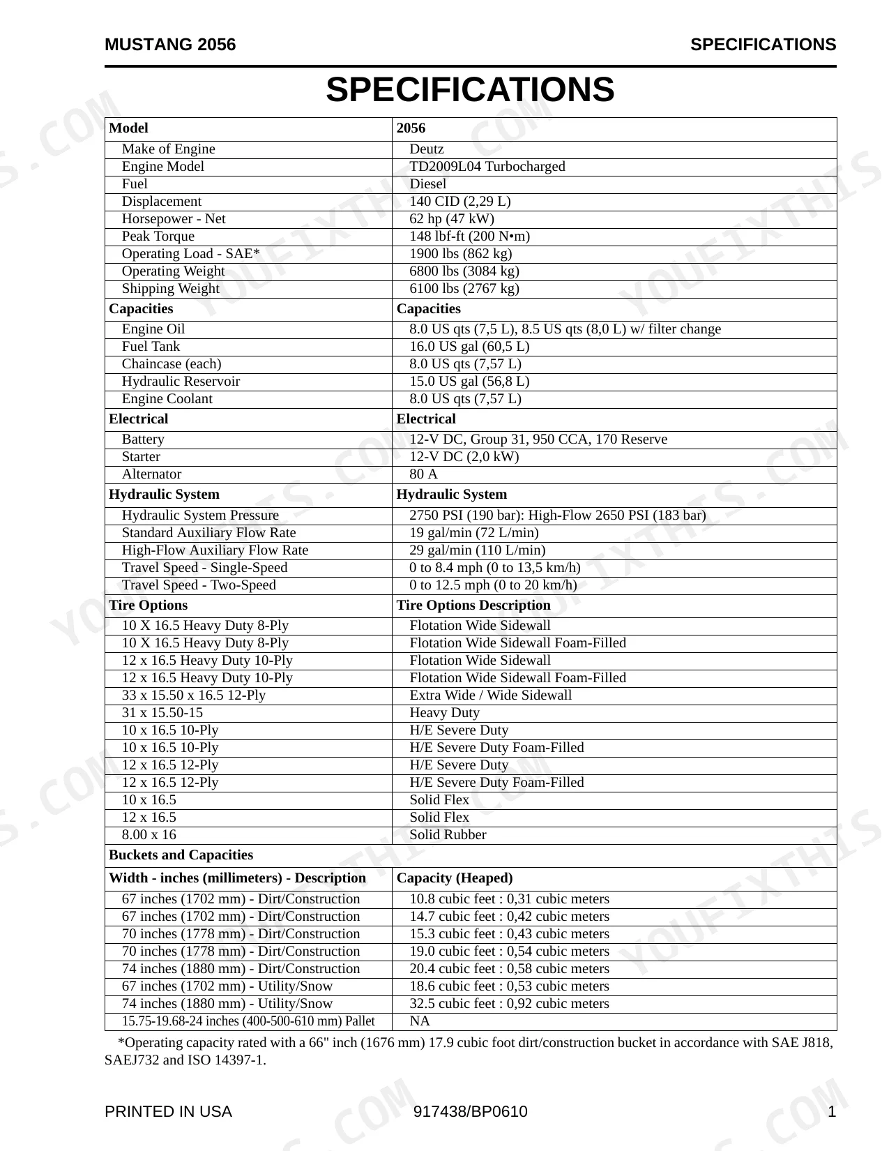
Quick Reference Specifications
| Specification | Value | Page |
|---|---|---|
| Axle housing locknuts torque | 280 ft.-lbs. (380 N•m) | p. 50 |
| Wheel nut torque | 180 ft.-lbs. (244 N•m) | p. 50 |
| Hydraulic oil filter element replacement interval | when filter indicator on filter head shows red | p. 20 |
| Hydraulic Oil Reservoir capacity | 15 U.S. gallons (56,8 liters) | p. 19 |
| Hydraulic Oil Reservoir drain/fill interval | every 500 hours of operation or annually | p. 19 |
| Battery specifications | 12-V DC, Group 31, 950 CCA, 170 Reserve | p. 9 |
| Starter specifications | 12-V DC (2,0 kW) | p. 9 |
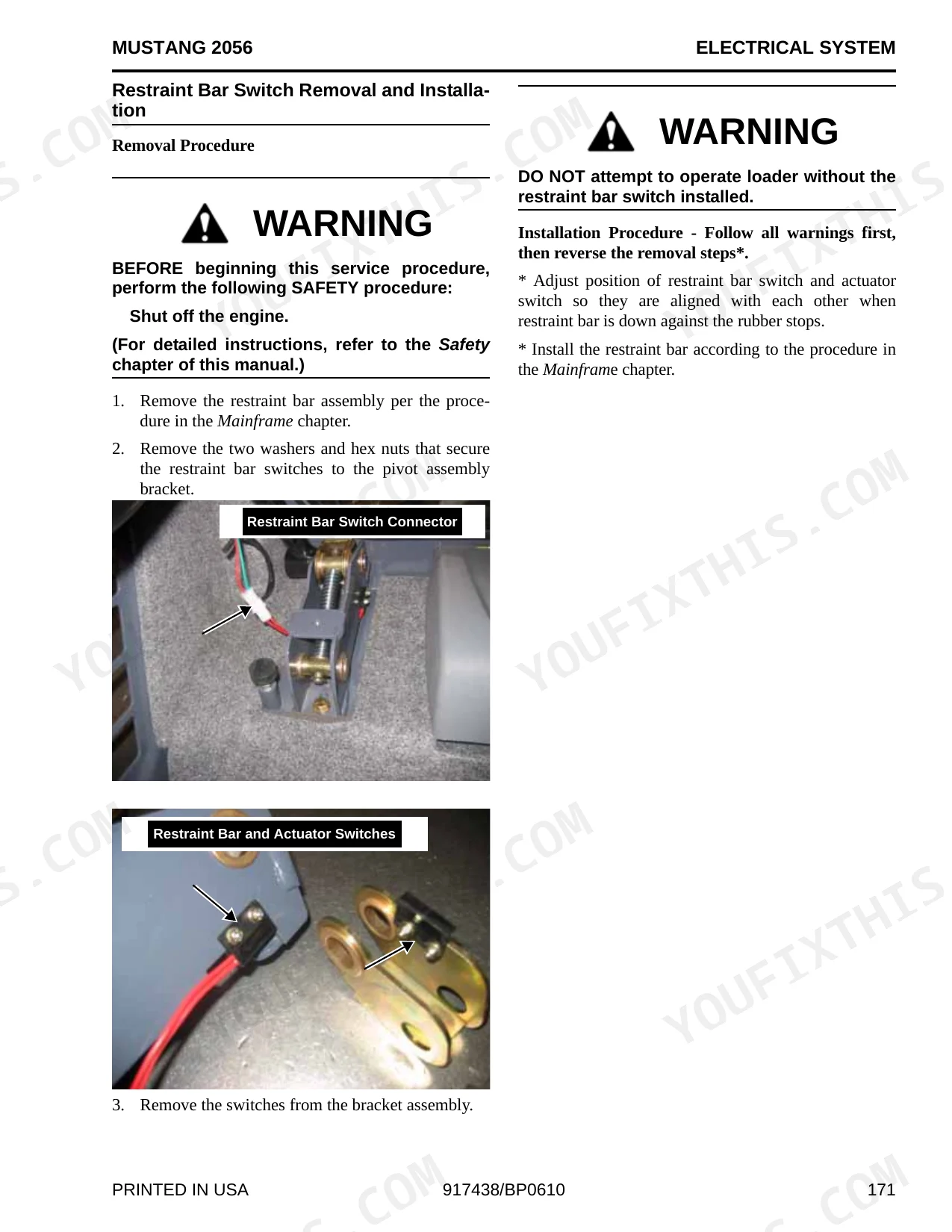
| Restraint bar switch and actuator switch alignment | aligned with each other when restraint bar is down against the rubber stops | p. 171 |
| Travel Speed - Single-Speed | 0 to 8.4 mph (0 to 13,5 km/h) | p. 9 |
| Travel Speed - Two-Speed | 0 to 12.5 mph (0 to 20 km/h) | p. 9 |
| Lift/Tilt Cylinder locknut torque | 350 ft.-lbs. (474 N•m) | p. 133 |
| Lift Arm Stop Installation and Adjustment (capscrew torque) | 80 ft.-lbs. (108 N•m) | p. 136 |
Mustang 2056 Common Problems This Manual Covers
Cranks but will not stay running
The engine starting then stalling after a short run usually points to fuel delivery, air in the fuel system, or a weak battery and starter. The Engine section covers fuel system and starting diagnostics.
Manual Section: EngineWeak or unresponsive hydraulics
Low hydraulic fluid, clogged filters, or a worn pump can leave the hydraulics slow or unresponsive. The Hydraulic System section covers pressure testing and control valve service.
Manual Section: Hydraulic SystemLoader will not drive
Loss of drive can come from charge pressure loss, a control fault, or contaminated fluid affecting the hydrostatic drive. The Hydrostatic Drive section covers charge pressure tests and drive diagnostics.
Manual Section: Hydrostatic DriveOverheating under load
Restricted cooling, low oil, or dirty filters can cause overheating and lost power. The Lubrication System section explains fluid checks and service intervals.
Manual Section: Lubrication SystemSafety interlock shutdown
A seat bar or restraint bar switch fault can shut the machine down or block operation. The Electrical System section covers the restraint bar switch alignment and interlock circuit.
Manual Section: Electrical SystemDrive chain and axle wear
A loose drive chain or worn axle bearings cause weak, noisy travel. The Wheel Drives section covers drive chain adjustment and axle housing service.
Manual Section: Wheel DrivesFrequently Asked Questions
What machine and engine does this manual cover?
It covers the Mustang 2056 skid-steer loader, built from 2011 to 2016 with the turbocharged Deutz TD2009L04 diesel engine.
Does it include torque specifications?
Yes. The manual lists torques such as 180 ft-lbs (244 Nm) for the wheel nuts and 280 ft-lbs (380 Nm) for the axle housing locknuts. p. 50
What is the hydraulic system pressure?
The Specifications give a standard hydraulic system pressure of 2750 psi (190 bar), with pressure test procedures for the control valve and high-flow circuits. p. 9
Is this the complete factory service manual?
Yes. This is the full 221 page Mustang 2056 service manual, part number 917438, covering troubleshooting, testing, adjustment, and disassembly procedures.
What do I get after purchasing this Mustang 2056 manual?
A 221-page Service Manual in searchable PDF format, available the moment you complete checkout. View it on a computer, tablet, or phone, with no shipping wait.
Is this Mustang 2056 Service Manual printable?
No restrictions at all. Print individual pages, full chapters, or the entire manual. The PDF is completely unlocked.
Are hydraulic system diagrams in this Mustang 2056 Service Manual?
Included. Hydraulic system schematics cover all circuits, control valves, and component specifications for the Mustang 2056.


Reviews
There are no reviews yet.