


This is the factory service manual for the Mustang 634 Telehandler, publication 913251, running 310 pages of repair, testing, and adjustment procedures for the machine and its John Deere 4045T engine.It covers engine removal and installation, the electrical schematics and circuit troubleshooting, transmission and front and rear axle service, the complete hydraulic system, and every boom component from the lift, tilt, and extend cylinders to the telescoping chain and roller bearings. Specifications include fluid capacities, SAE and metric torque charts, and relief pressures such as the 3000 PSI main relief and 2000 PSI steering relief.Owners and independent mechanics can use it to diagnose hydraulic and electrical faults, rebuild cylinders, adjust the leaf chains, and reset the machine to spec. The PDF has a text layer and bookmarks, so you can search a term, jump to the section, and print only the pages you need in the shop.
What's Inside This Mustang 634 Manual
| System | Pages | Key Topics |
|---|---|---|
| Personal Safety Information and Decal Locations | 6 | Safety Rules and Reminders, Modifications, Nameplates, Markings and Load Capacities, Roll-Over Protective Structure (ROPS), Protect the Environment, Decal Locations |
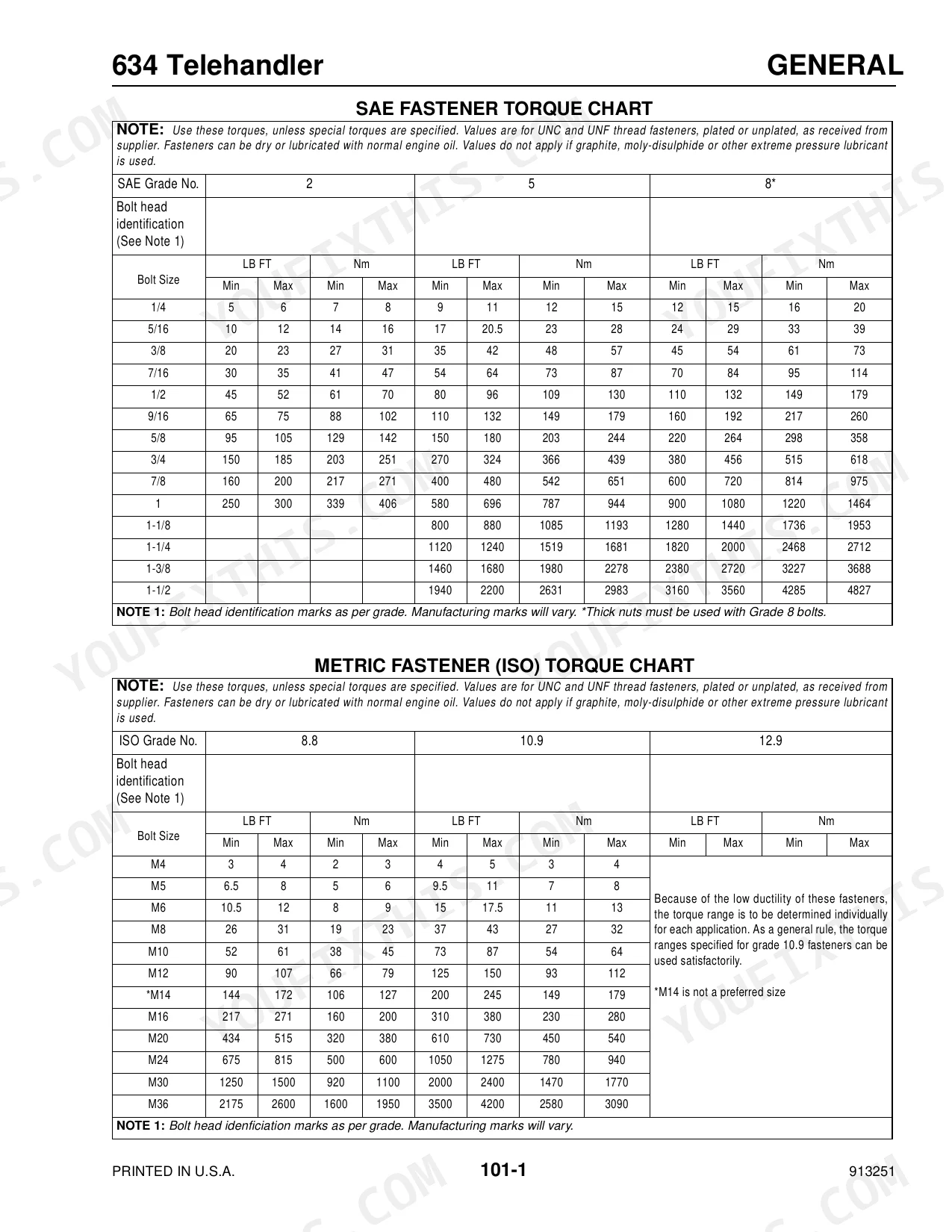
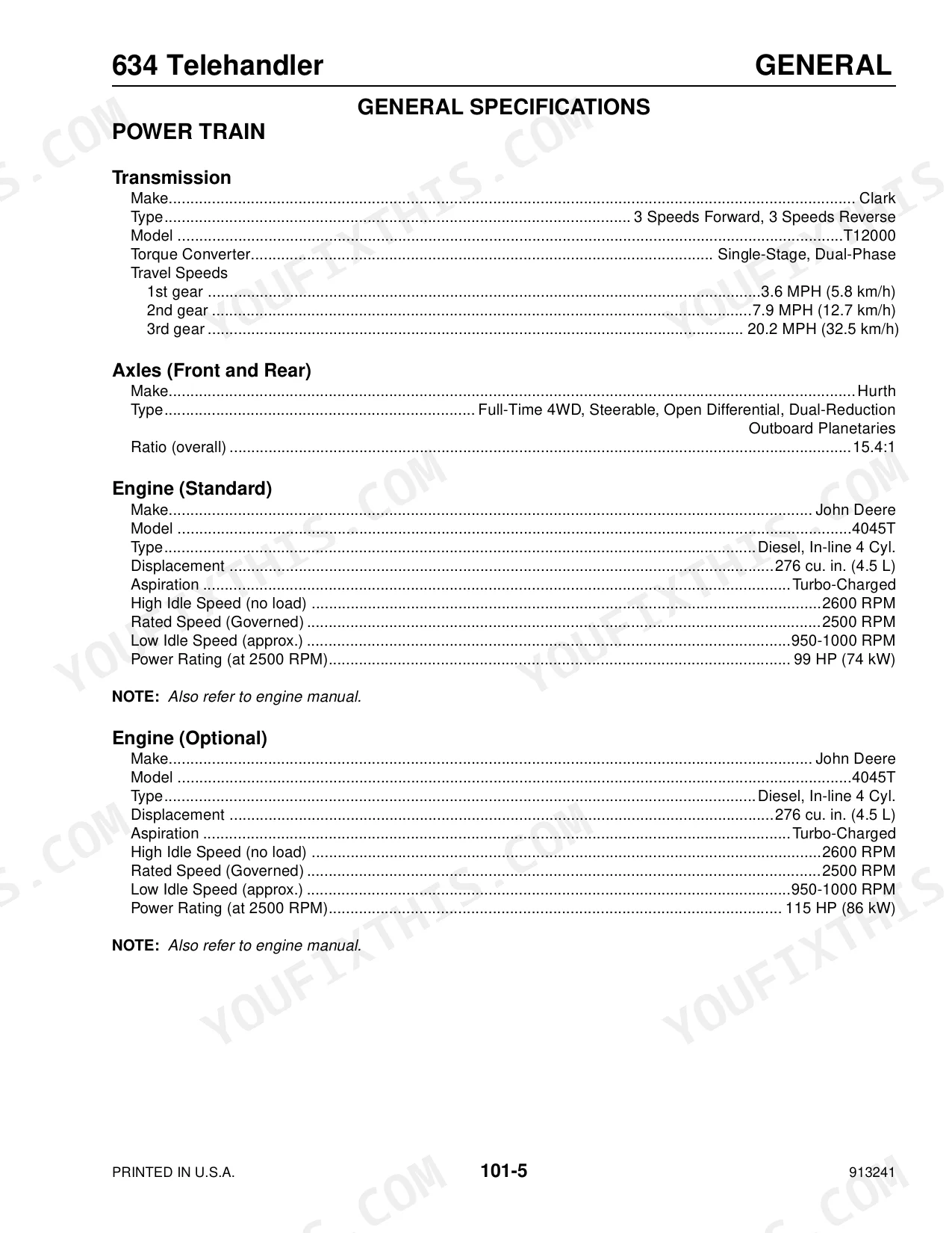
| General Information and Specifications | 18 | Sae Fastener Torque Chart, Metric Fastener (Iso) Torque Chart, Standard Torque Data for Hydraulic Tubes and Fittings, Indicator and Operation Symbols, Fluid Capacities and Types |
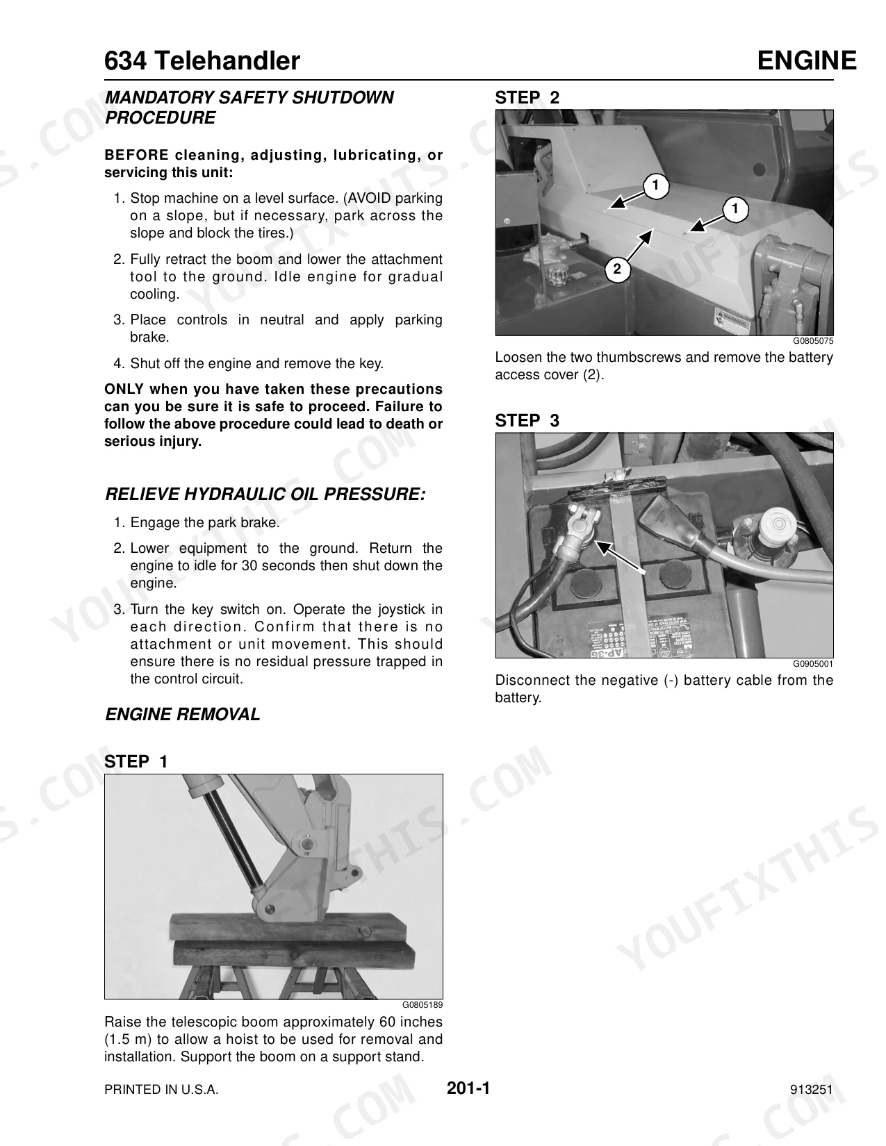
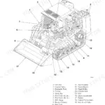
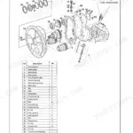
| Engine Removal and Installation | 30-57 | Engine Removal, Relieve Hydraulic Oil Pressure, Engine Installation, General Information |
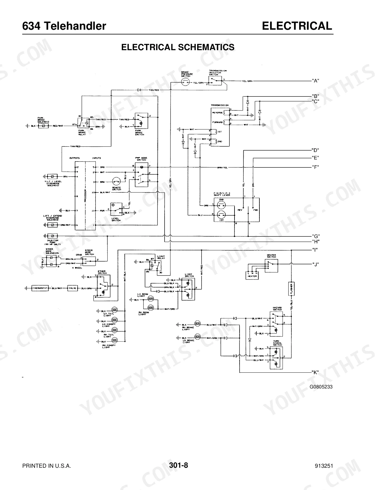
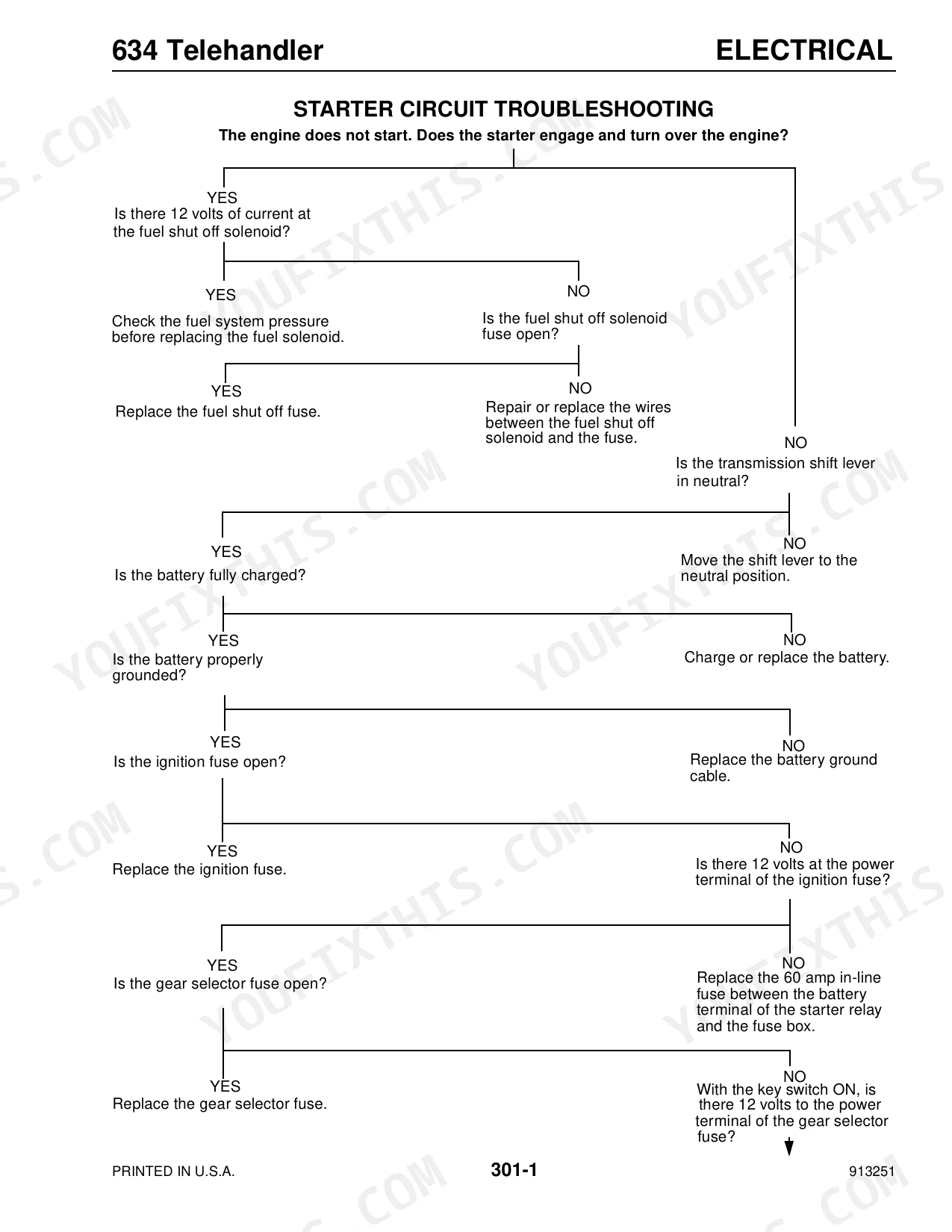
| Electrical Schematics, Troubleshooting Testing & Adjustment Procedures | 58-81 | Starter Circuit Troubleshooting, Park Brake Circuit Troubleshooting, Steering Mode Circuit Troubleshooting, Instrument Panel or Panel Bulb Replacement, Electrical Schematics |
| Battery Removal and Installation | 82-89 | Battery Removal, Battery Installation |
| Steering Control Valve Removal and Installation | 90-97 | Steering Control Valve Removal, Steering Control Valve Installation |
| Transmission Removal and Installation | 98-121 | Transmission Removal, Transmission Installation |
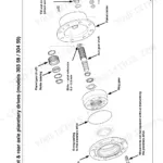
| Rear Axle Removal and Installation | 122-133 | Rear Axle Removal, Rear Axle Installation, Release Hydraulic Oil Pressure, General Information |
| Front Axle Removal and Installation | 134-145 | Front Axle Removal, Relieving Hydraulic Pressure, Front Axle Installation, General Information |
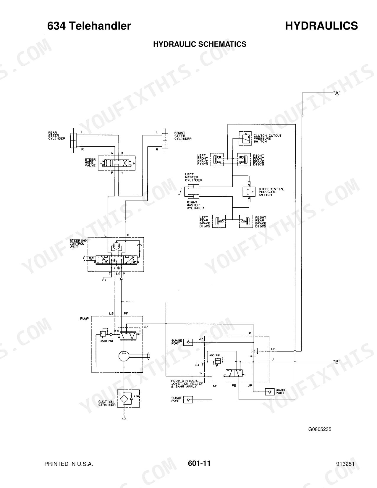
| Hydraulic Schematics, Troubleshooting Testing & Adjustment Procedures | 146-189 | Hydraulic Specifications, Troubleshooting, Hydraulic Schematics, Hydraulic System Testing, Main Control Valve Pressure Relief Test and Adjustment |
| Hydraulic Pump Removal and Installation | 190-197 | Hydraulic Pump Removal, Hydraulic Pump Installation |
| Frame Leveling Cylinder Removal and Installation | 198-205 | Relieving Hydraulic Pressure for the Frame Leveling Cylinder, Frame Leveling Cylinder Removal, Frame Leveling Cylinder Installation |
| Tilt Cylinder Removal and Installation | 206-213 | Tilt Cylinder Removal, Tilt Cylinder Installation, Relieving Hydraulic Pressure for the Tilt Cylinder |
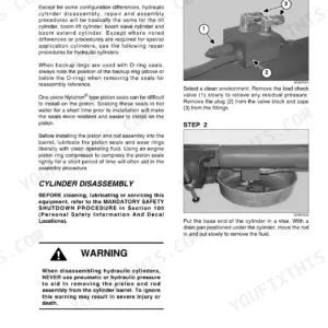
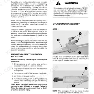
| Hydraulic Cylinder Repair | 214-225 | Cylinder Disassembly, Cylinder Assembly, General Information |
| Slave Cylinder Removal and Installation | 226-233 | Relieving Hydraulic Pressure for the Slave Cylinder, Slave Cylinder Removal, Slave Cylinder Installation |
| Lift Cylinder Removal and Installation | 234-241 | Relieving Hydraulic Pressure for the Lift Cylinder, Lift Cylinder Removal, Lift Cylinder Installation |
| Boom Extend Cylinder Removal and Installation | 242-249 | Relieving Hydraulic Pressure for the Extend Cylinder, Extend Cylinder Removal, Extend Cylinder Installation |
| Boom Assembly Removal and Installation | 250-261 | Boom Assembly Removal, Boom Assembly Installation, Release Hydraulic Oil Pressure, Relieving Hydraulic Pressure for the Tilt Cylinder, General Information |
| Single and Double Leaf Chain Adjustment | 262-265 | Leaf Chain Adjustment, Leaf Chain Maintenance, General Information |
| Inner Boom Section Removal and Installation | 266-281 | Relieving Hydraulic Pressure for the Boom Extend Cylinder, Inner Boom Removal, Inner Boom Installation, Relieving Hydraulic Pressure for the Tilt Cylinder, General Information |
| Telescoping Boom Double Chain and Roller Bearing Replacement | 282-289 | Double Chain Roller Bearing Removal, Double Chain Roller Bearing Installation |
| Telescoping Boom Single Chain and | 290-297 | Removal, Installation, Single Chain Roller Bearing Replacement |
| Intermediate Boom Section Removal and Installation | 298-310 | Intermediate Boom Removal, Intermediate Boom Installation, General Information |
Every system also includes mandatory safety shutdown procedure.
Quick Reference Specifications
| Specification | Value | Page |
|---|---|---|
| Housing bell bolts torque | 40 to 45 lb.-ft. (54 to 61 Nm) | p. 44 |
| Wheel nuts torque (Rear Axle) | 450 ft.-lbs. (610 Nm) | p. 128 |
| Wheel nuts torque (Front Axle) | 450 ft.-lbs. (610 Nm) | p. 141 |
| Recommended Tire Type | 15.00 x 19.5 12-ply, 405/70 R20 x M27 Traction Type | p. 27 |
| Ground Clearance | 14” (356 mm) | p. 27 |
| Hydraulic tube nuts torque (1/2 inch tubing) | 35 to 40 LB FT (47 to 54 Nm) | p. 21 |
| Hydraulic Filter Type | Remote, 10 Micron, Replaceable Element | p. 25 |
| Hydraulic Filter Rated Flow | 100 GPM (379 L/min) | p. 25 |
| Boom lift pressure (target) | 3000 psi (207 bar) | p. 153 |
| Engine Crankcase Capacity (with filter) 4045T (John Deere) | 14.0 qts. (13.3 L) | p. 23 |
| Cooling System Capacity | 17.2 qts. (16.3 L) | p. 23 |
| Transmission Oil Capacity (with cooler) | 24 qts. (22.7 L) | p. 23 |
Mustang 634 Common Problems This Manual Covers
Boom loses lifting power or drifts
Slow boom movement, weak lift, or external hydraulic leaks usually trace to low fluid, worn seals, damaged hoses, or a failing pump. The hydraulic troubleshooting, testing, and adjustment section walks through pressure checks against the 3000 PSI target.
Manual Section: Hydraulic Schematics, Troubleshooting Testing & Adjustment Procedures p. 146Hard starting or heavy exhaust smoke
No-starts, hard starts, and excessive smoke on the 4045T engine point to fuel delivery restriction, clogged filters, or cooling problems. The engine section covers removal, installation, and the related service points.
Manual Section: Engine Removal and Installation p. 30Intermittent electrical faults or dead machine
A machine that starts unreliably or goes dead often has a wiring or circuit fault. The electrical section provides starter, park brake, and steering mode circuit troubleshooting plus the full schematics.
Manual Section: Electrical Schematics, Troubleshooting Testing & Adjustment Procedures p. 58Corroded or loose battery terminals
Loose or corroded battery connections are a common cause of no-crank and unreliable starting on telehandlers. This section covers correct battery removal and installation.
Manual Section: Battery Removal and Installation p. 82Leaking or worn hydraulic cylinder seals
Cylinders that weep oil or lose holding pressure need reseal work. The cylinder repair section details disassembly and assembly so seals and gaskets go back correctly.
Manual Section: Hydraulic Cylinder Repair p. 214Loose or worn boom leaf chains
Stretched or improperly tensioned leaf chains cause boom lag and uneven extension. This section covers leaf chain adjustment and maintenance.
Manual Section: Single and Double Leaf Chain Adjustment p. 262Frequently Asked Questions
Which machine does this manual cover?
It is the service manual for the Mustang 634 Telehandler, publication number 913251, with the John Deere 4045T engine. It covers 310 pages of repair, testing, and adjustment procedures.
Does it include torque values and fluid capacities?
Yes. The General Information and Specifications section provides SAE and metric fastener torque charts, hydraulic tube and fitting torque data, and fluid capacities and types for the machine. p. 18
Can I use it to troubleshoot the hydraulic system?
Yes. The hydraulic schematics, troubleshooting, testing, and adjustment section covers hydraulic specifications, system testing, and the main control valve pressure relief test and adjustment. p. 146
Can I search the text and jump between sections?
Yes. This PDF has a real text layer and bookmarks, so you can search for a part or procedure and navigate straight to the right section rather than scrolling page by page.
How quickly can I access this Mustang 634 manual after buying?
The 310-page searchable PDF downloads instantly after checkout. Open it on a laptop, tablet, or phone and bring it straight to the shop floor.
Are there any print restrictions on this Mustang 634 manual?
Absolutely. No DRM or copy protection. Print the whole manual or just the pages you need. Any home or office printer works.
Are hydraulic system diagrams in this Mustang 634 Service Manual?
Full hydraulic system diagrams are included, covering circuits, valve locations, and hydraulic component specs for the Mustang 634.

Reviews
There are no reviews yet.