


This is the factory service manual for the Mustang 519 Telehandler, part number 913302, covering 224 pages of assembly, disassembly, testing, and troubleshooting for the machine and its TD2009L04 engine.Sections run from safety and general specifications through engine removal and installation, electrical troubleshooting, steering, the hydrostatic power train, the full hydraulic system, the telescoping boom, and the chassis covers. Reference data includes SAE and metric torque charts, fluid capacities, and pressures such as the 3350 PSI main control valve relief and 2400 PSI steering relief, with the engine rated at 64 HP at 2600 RPM.Owners and mechanics can use it to chase no-start faults, weak or erratic hydraulics, and steering problems, then rebuild and reset the machine to factory values. The PDF is searchable and bookmarked, so you can find a procedure fast and print only the pages you need at the bench.
What's Inside This Mustang 519 Manual
| System | Pages | Key Topics |
|---|---|---|
| General | 5-26 | Safety (Mandatory Safety Shutdown Procedure, Rules and Reminders, Modifications, Nameplates, Markings and Load Capacities, Roll Over Protective Structure) |
| Engine | 27-46 | Engine Removal and Installation, General Table of Contents, Engine Removal, Special Torque Values, Step 1, Step 2, Step 3, Step 4 |
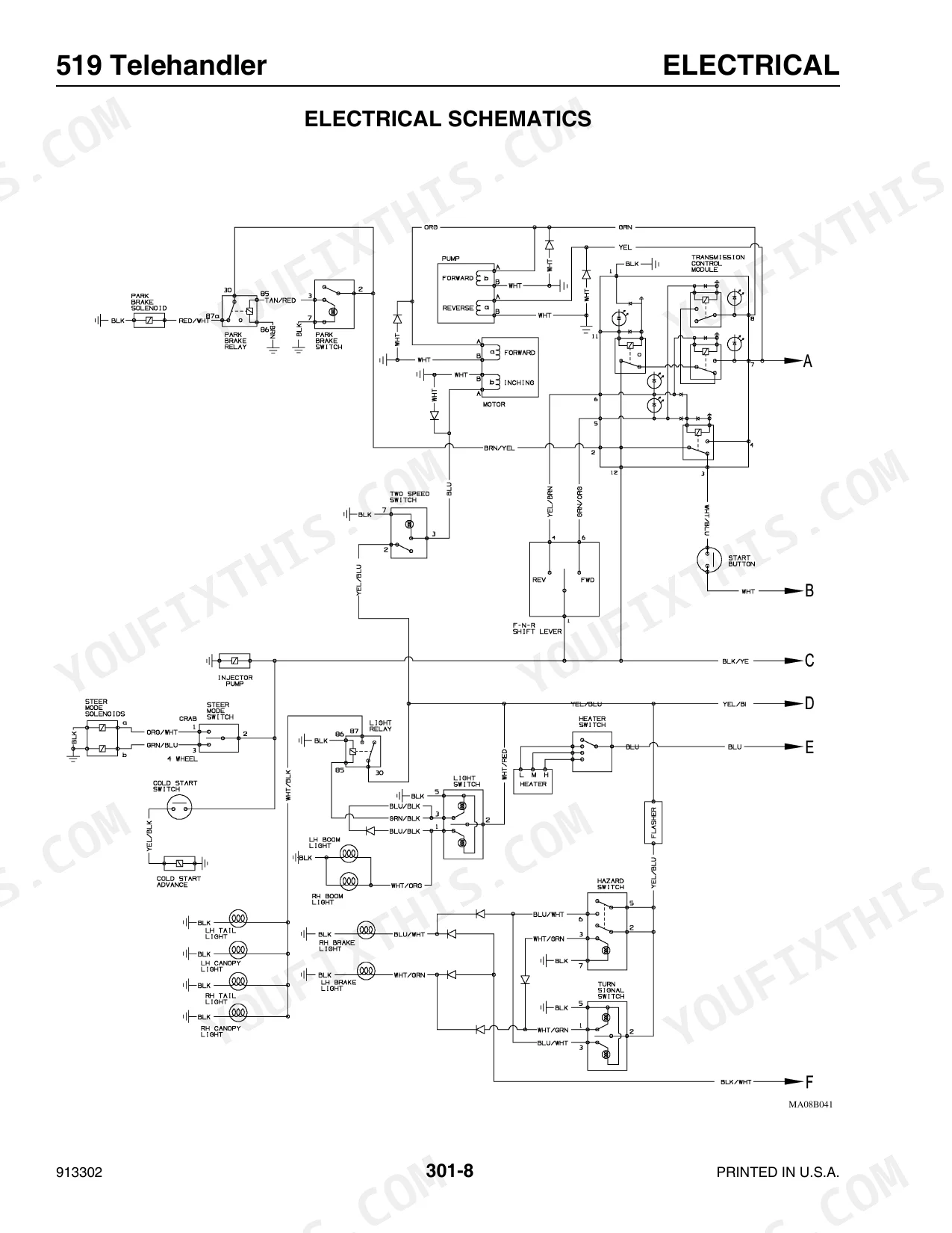
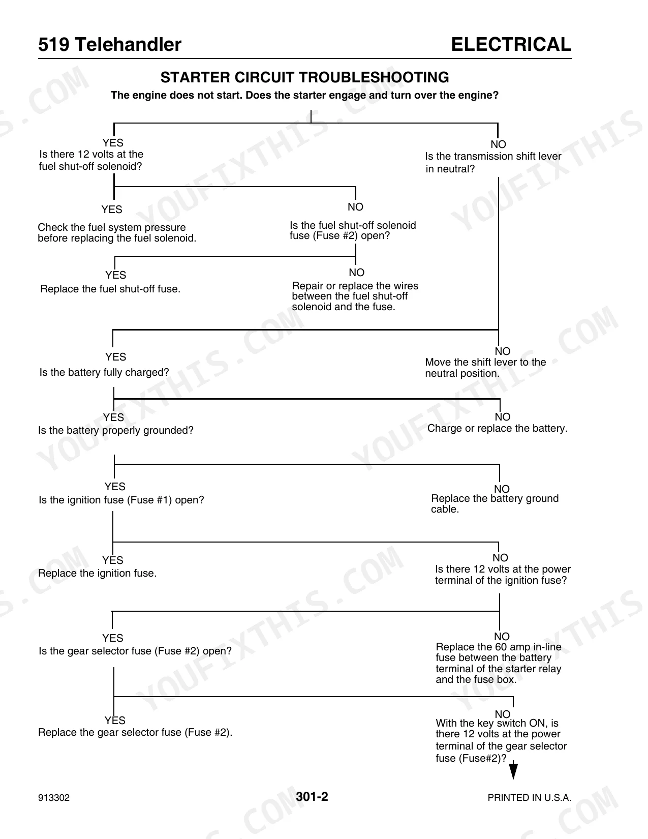
| Electrical | 47-76 | Troubleshooting (Starter Circuit Troubleshooting, Park Brake Circuit Troubleshooting, Steering Mode Circuit Troubleshooting), Instrument Panel or Panel Bulb Replacement |
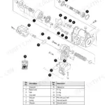
| Steering | 77-84 | General Table of Contents, Steering Control Valve Removal, Step 1, Step 2, Step 3, Step 4, Step 5, Step 6 |
| Power Train | 85-118 | Hydrostatic Pump Removal and Installation, General Table of Contents, Hydrostatic Pump Removal, Step 1, Step 2, Step 3, Step 4, Step 5 |
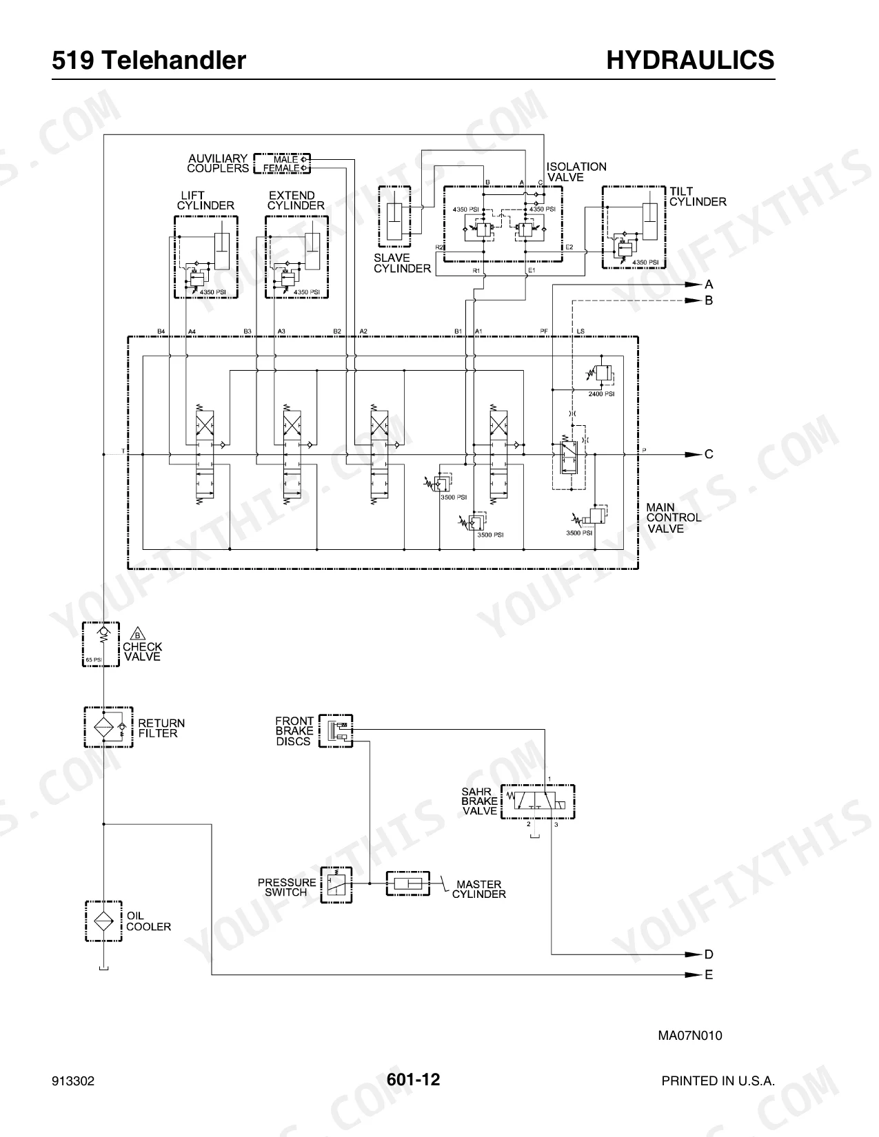
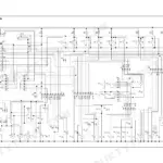
| Hydraulic System | 119-198 | Hydraulic Schematics, Troubleshooting, Testing & Adjustment Procedures (Introduction), Hydraulic Specifications |
| Telescoping Boom | 199-216 | Boom Assembly Removal and Installation, Inner Boom Removal and Installation |
| Chassis | 217-224 | Hoods and Covers, Engine Cover Removal, Engine Cover Installation, Front Cover Access, Radiator Cover Removal, Radiator Cover Installation, Rear Cover Access |
Quick Reference Specifications
| Specification | Value | Page |
|---|---|---|
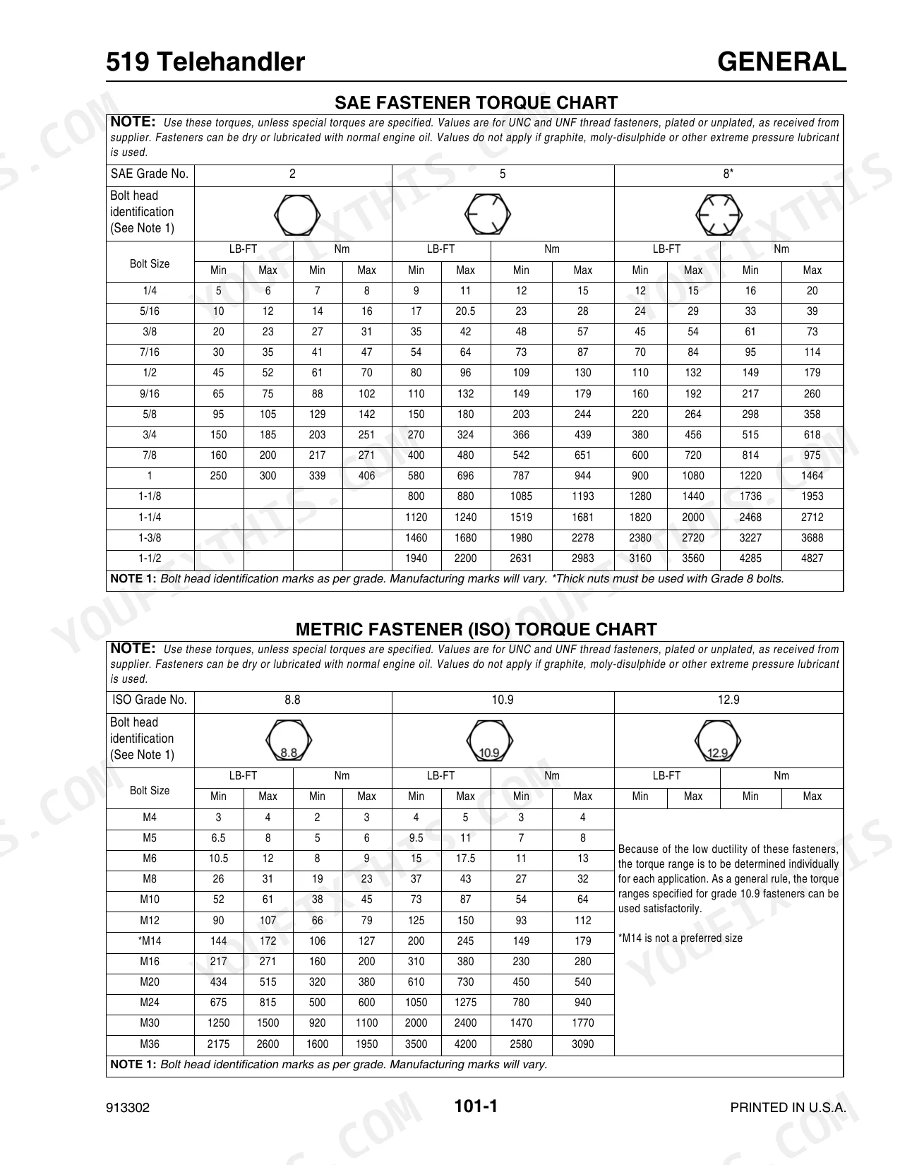
| Wheel Nuts Torque | 450 ft.-lb. (607 Nm) | p. 101 |
| Battery Type | One - 950 minimum CCA Low-Maintenance Type | p. 23 |
| Battery Voltage (fully charged) | 12 to 13 volts | p. 58 |
| Neutral Start Switch Type | Standard | p. 23 |
| Steering Column Shaft Center Nut Torque | 35 lb.-ft. (47 Nm) | p. 82 |
| High Pressure Hydraulic Hose Flange Bolts Torque | 45 to 50 lb.-ft. (61 to 68 Nm) | p. 28 |
| Hydraulic Filter Type | Return-type, 16-Micron, Replaceable Element | p. 22 |
| Hydraulic Filter Rated Flow | 35 GPM (132 L/min) | p. 22 |
| Pump Type | Single-Section Gear-Type | p. 22 |
| Pump Displacement (revolution) | 1.95 cu. in. (32 cc) | p. 22 |
| Steering System Type | Fixed-Displacement, Rotary | p. 22 |
| Steering Displacement/Rev. | 7.3 cu. in. (120 cc) | p. 22 |
Mustang 519 Common Problems This Manual Covers
Machine cranks but will not start
Battery corrosion, a weak battery, or faulty electrical controls are common no-start causes on telehandlers. The electrical section covers starter, park brake, and steering mode circuit troubleshooting.
Manual Section: Electrical p. 47Weak or erratic hydraulic functions
Low or contaminated hydraulic oil, pump wear, or valve faults leave lift and boom functions slow or unresponsive. The hydraulic section provides schematics, testing, and adjustment procedures with the hydraulic specifications.
Manual Section: Hydraulic System p. 119Abnormal or heavy steering response
Steering that feels heavy, wanders, or responds poorly often traces to the steering control valve or its hydraulic supply. This section covers steering control valve removal and installation.
Manual Section: Steering p. 77Overheating or power loss under load
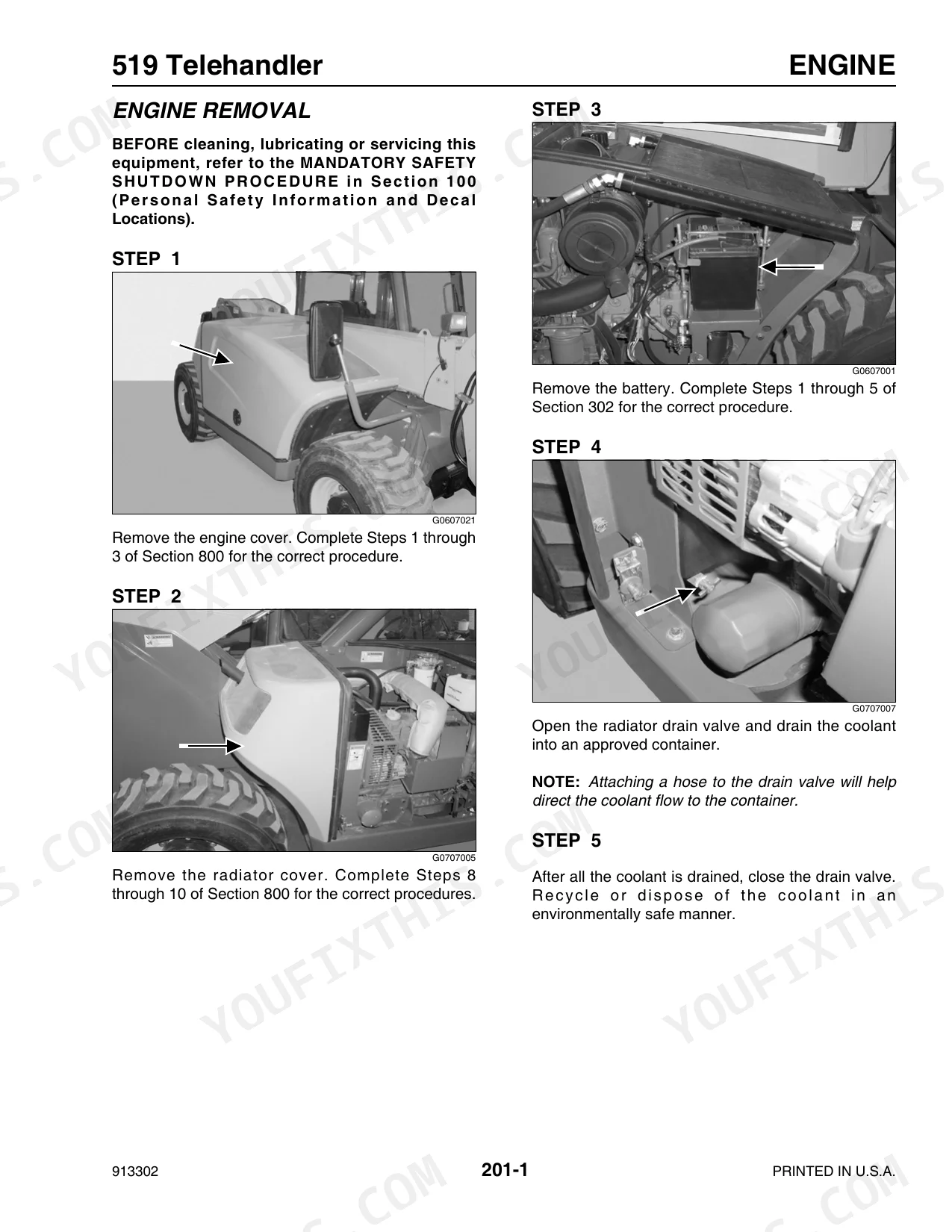
Cooling neglect, restricted airflow, or fluid problems can leave the engine down on power under load. The engine section covers removal, installation, and the related special torque values.
Manual Section: Engine p. 27Weak or sluggish hydrostatic drive
A machine that is slow to move or lacks drive power may have a hydrostatic pump fault. The power train section covers hydrostatic pump removal and installation with the relevant specifications.
Manual Section: Power Train p. 85Boom wear, drift, or misalignment
Worn boom components and pads cause lag and uneven extension. The telescoping boom section covers boom assembly and inner boom removal and installation.
Manual Section: Telescoping Boom p. 199Frequently Asked Questions
Which telehandler does this manual cover?
It is the service manual for the Mustang 519 Telehandler, part number 913302, with the TD2009L04 engine rated at 64 HP. It runs 224 pages of service, testing, and troubleshooting.
Does it list torque specs and fluid capacities?
Yes. The General section includes SAE and metric fastener torque charts, standard torque data for hydraulic tubes and fittings, and fluid capacities and types for the machine. p. 5
Can it help me troubleshoot electrical no-start problems?
Yes. The Electrical section covers starter circuit, park brake circuit, and steering mode circuit troubleshooting, plus instrument panel and bulb replacement. p. 47
Can I search the manual text?
Yes. This PDF has a text layer and bookmarks, so you can search for a spec or procedure and jump directly to the section instead of paging through the whole file.
What do I get after purchasing this Mustang 519 manual?
This is a 224-page searchable PDF ready for immediate download. Works on any device — pull it up on your phone while you're under the hood. No shipping, no waiting.
Is this Mustang 519 Service Manual printable?
Absolutely. No DRM or copy protection. Print the whole manual or just the pages you need. Any home or office printer works.
Does this Mustang 519 manual include hydraulic schematics?
Yes — complete hydraulic schematics with flow diagrams, valve configurations, and pressure specifications are included.


Reviews
There are no reviews yet.