


This is the factory service manual for the Mustang ML42 and ML43 wheel loaders, sold in some markets as the 318, 418, and 418 Telescopic and built as models 308 63, 311 66, and 311 00. The 198 page manual, part number 50940189, covers the Perkins 704-30 diesel engine, the hydrostatic drive, axles, brakes, steering, work hydraulics, and the electrical system.Inside you get full specifications, tightening torques, maintenance schedules, and step by step repair procedures for each machine. Owners and independent mechanics can use it to service the engine, diagnose the hydrostatic drive, check hydraulic oil and the reflux filter, and set correct torque values during reassembly.The download is a searchable PDF you can view on a computer, tablet, or phone, and you can print any page you need for the workshop.
What's Inside This Mustang Skid Steer Range Manual
| System | Pages | Key Topics |
|---|---|---|
| General & Specifications | 3-21 | Controls, Specifications, Frame, Engine, Power Train, Axles, Brakes, Steering, Work Hydraulics, Loader Unit, Electrical System, Tyres, Weights, Dimensions, Tightening Torques, Perkins Engine, Hydrostatic Drive |
| Maintenance | 22-37 | Hydraulic Oil Level and Change, Hydraulic Oil Reflux Filter, Gearbox and Axles, Rear Axle Transfer Gearbox, Front and Rear Axle Differentials, Engine Fluids and Lubricants, Service and Sealing Kits, Maintenance Plan, Proofs of Maintenance |
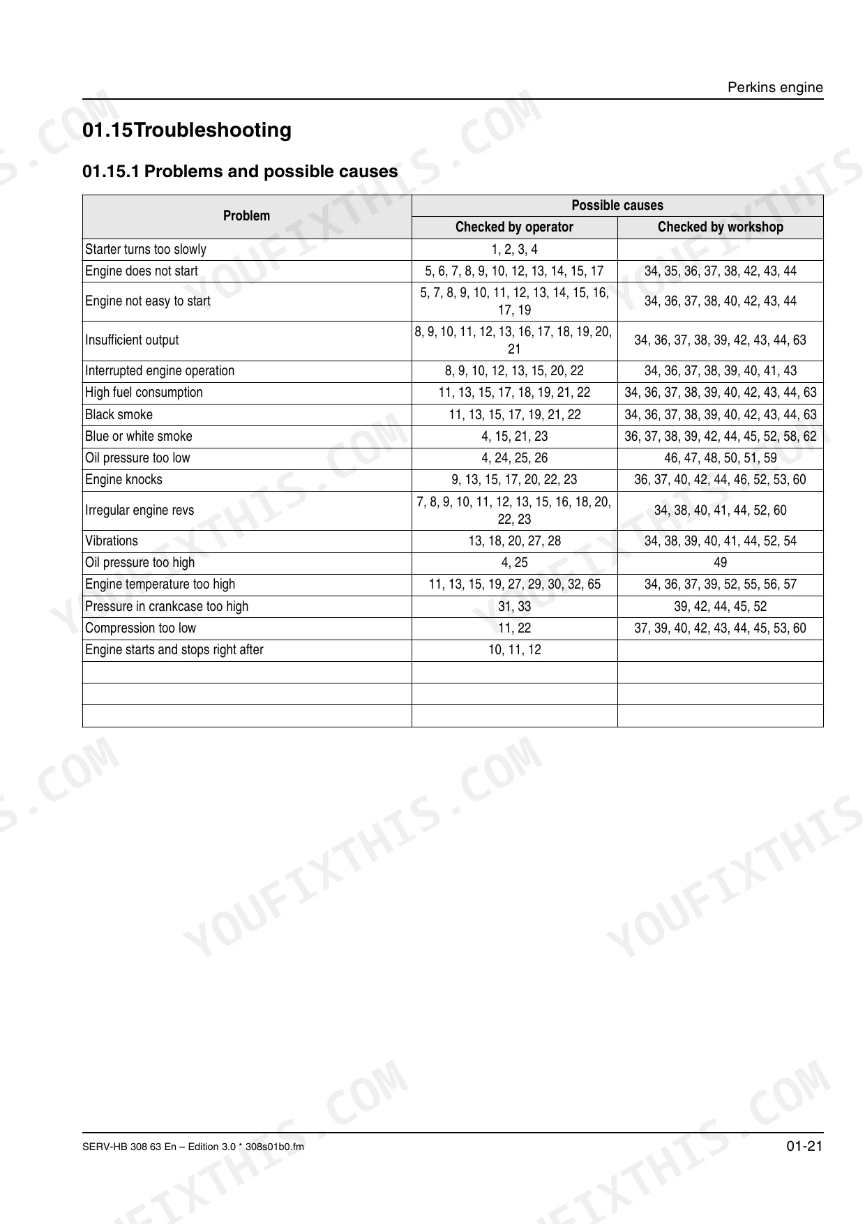
| Engine (Perkins) | 38-61 | Specifications 704-30, Tightening Torques, Crankcase Breather, Valve Cover, Rocker-Arm Shaft, Cylinder Head, Valve Tip Clearances, Fuel System, Injection Pump, Glow Plugs, Troubleshooting |
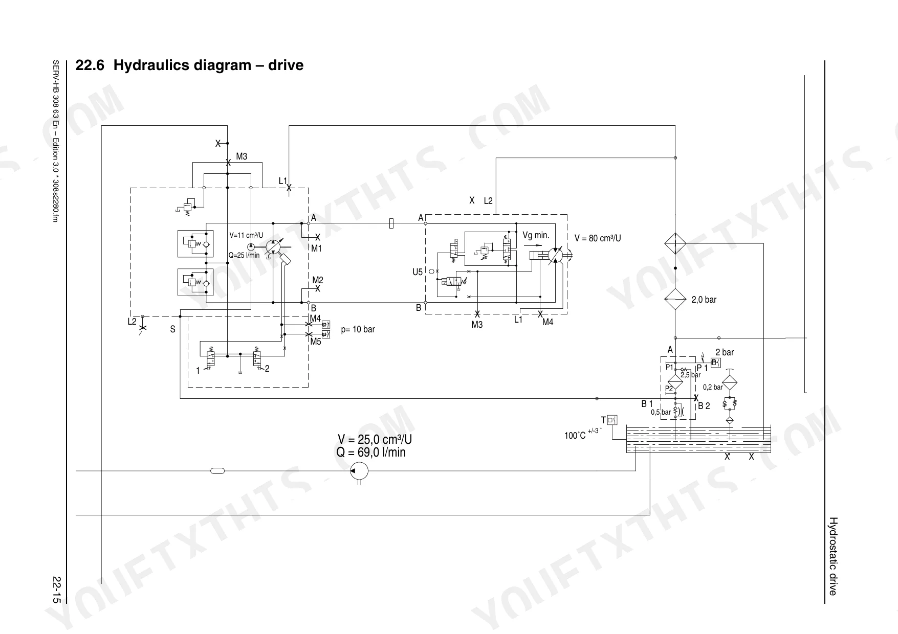
| Hydrostatic Drive | 62-79 | Hydraulic Pump, Variable Displacement Motor, Boost Pressure, Purge Valve, Proportional Valve, Hp Valves, Temperature Controller, Hydraulic Oil Circuit, Troubleshooting |
| Nfpe & Susmic Diagnostics | 80-100 | Nfpe System, Connection Diagram, Table of Errors, Susmic-Dia 1, Sensor Setup Procedure, Sensor Error Procedure, Sensor Check Procedure |
| Axles & Final Drives | 101-109 | Front and Rear Axle View, Planetary Drive, Self-Locking Differential, Final Drive, Steering Ram, Parking Brake, Transfer Gearbox, Rotary Shaft Lip Seal, Wheel Hub |
| Brakes | 110-115 | Service and Parking Brake, Brake Circuit, Brake Caliper, Master Brake Cylinder, Brake-Fluid Tank, Inching Potentiometer, Parking Brake Adjustment |
| Steering | 116-128 | Steering Circuit, Sevostat, Wheel Synchronization, Priority Valve, Steering Rams on Front/Rear Axles, Pressure Line, Control Unit |
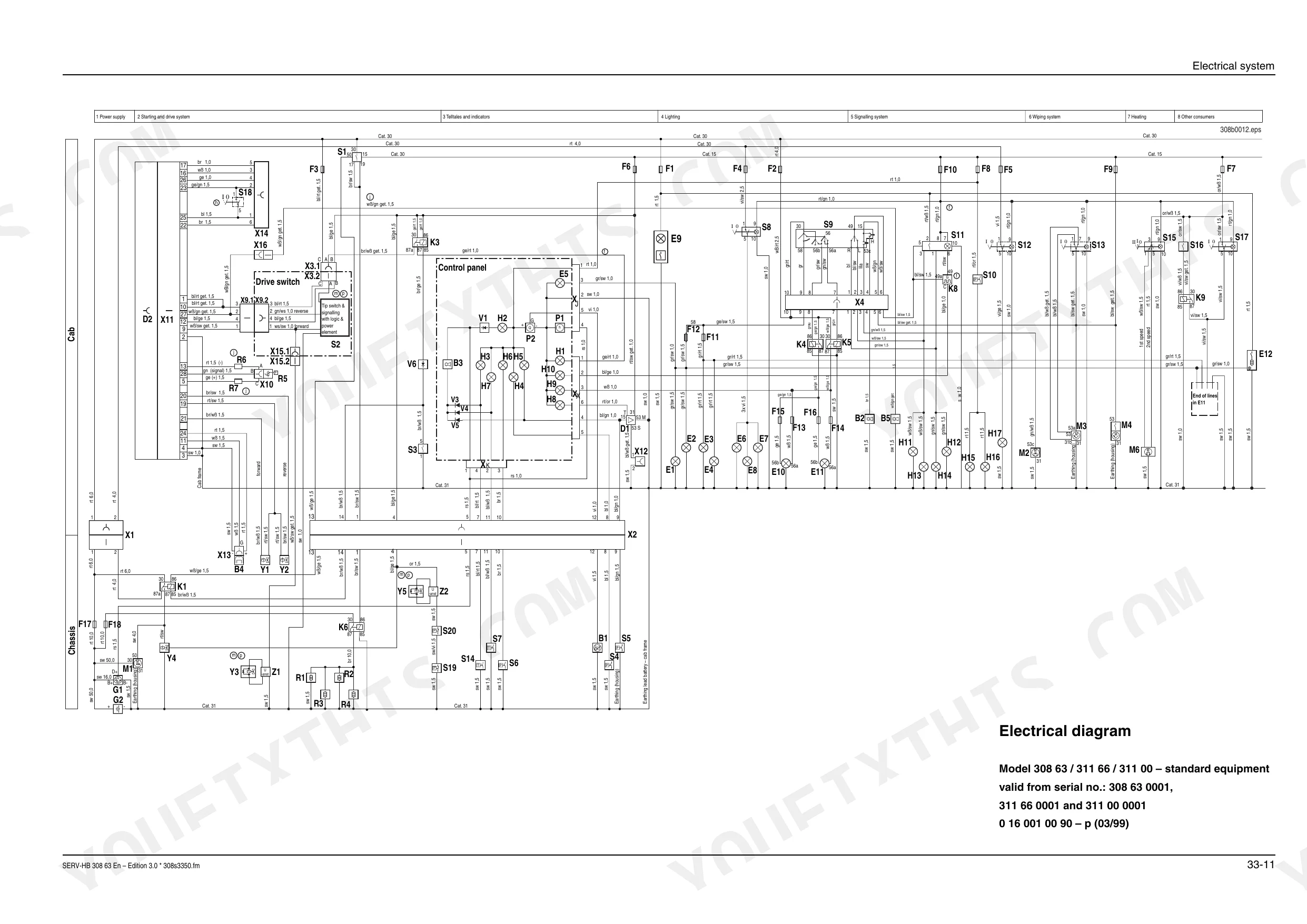
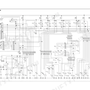
| Electrical System & Wiring Diagrams | 129-147 | Control Valve Actuation, Drive Switch Wiring, Fuse Box, Relay, Multifunctional Lever, Control Panel, Electrical Diagrams, Wiring Harnesses, Rocker Switch, Diagnostic Unit |
| Hydraulic System & Diagrams | 148-161 | Hydraulic Circuit, Lift Ram Circuit, Tilt Ram Circuit, Control Valve, Hose Burst Valve, Combined Suction and Reflux Filter, Hydraulics Diagram |
| Hydraulic Rams & Valves | 162-172 | Lift Ram, Tilt Ram, Quickhitch Facility, Locking Ram, Push-Out Cylinder, Priority Valve, Suction and Reflux Filter, Pressure Switch, Temperature Switch |
| Cab Heating | 173-175 | Heater Nozzle, Filter, Control Slide, Reflux Line, Feed Line, Front Window Connection |
| Controls & Operator Instruments | 176-198 | Multifunctional Lever, Rotary Switch, Hour Meter, Fuse Box, Brake Inching Pedal, Hydrostatic Steering, Accelerator Pedal, Control Panel, Parking Brake, Drive Mode Selection Switch |
Quick Reference Specifications
| Specification | Value | Page |
|---|---|---|
| All Models | ||
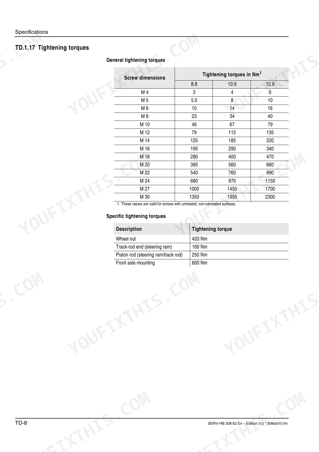
| General tightening torque M4 (8.8) | 3 Nm | p. 13 |
| General tightening torque M4 (10.9) | 4 Nm | p. 13 |
| Engine Displacement | 2955 cm³ | p. 6 |
| Hydraulic Oil Tank Capacity | 50 l | p. 8 |
| Wheel Nut Tightening Torque | 420 Nm | p. 13 |
| Sound Power Level | 97 dB (A) | p. 11 |
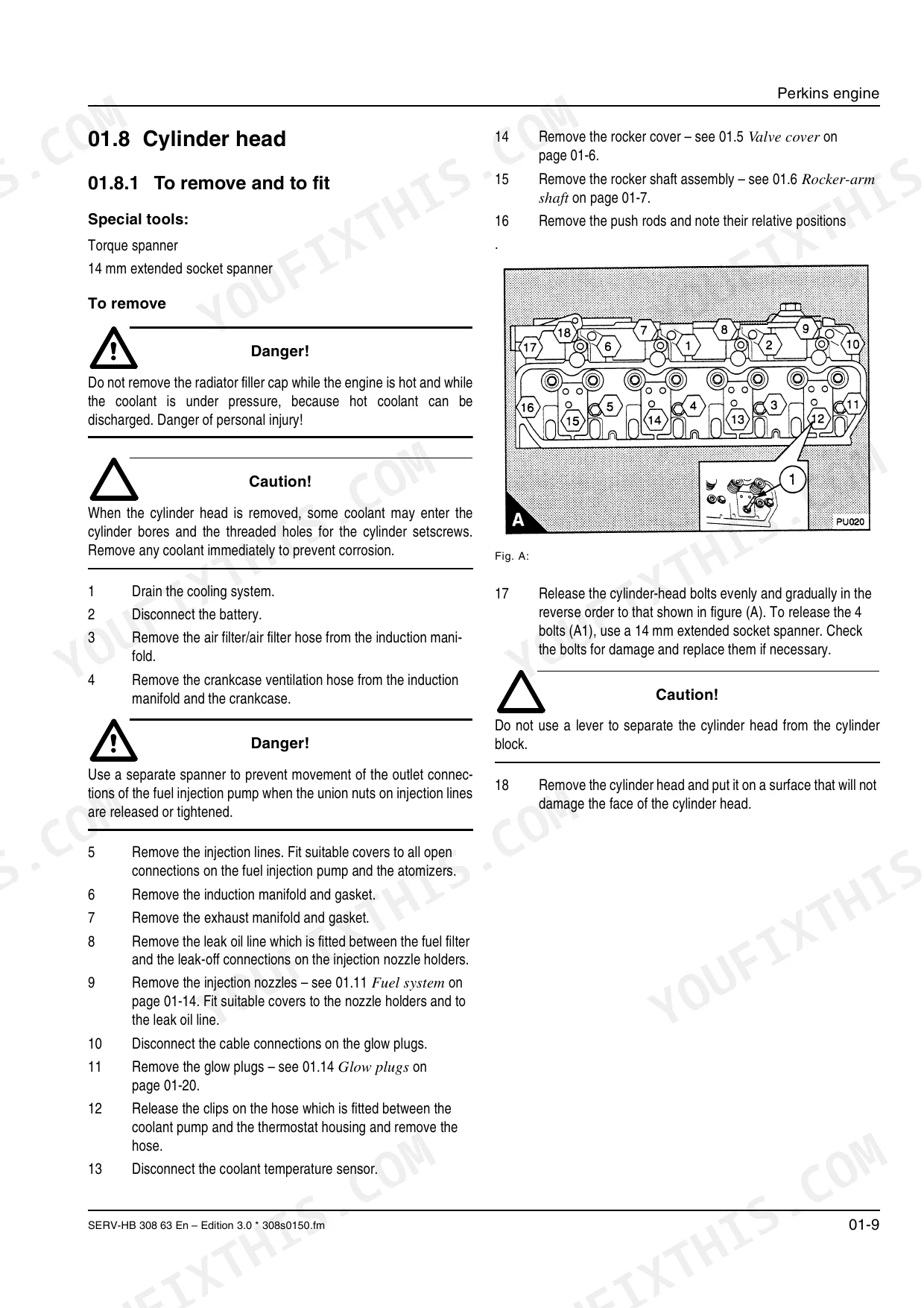
| Cylinder-head bolt Tightening Torque | 13 Nm | p. 43 |
| 318 (model 308 63) | ||
| Engine Power | 37 kW at 2300 min⁻¹ | p. 6 |
| 418 (model 311 66), 418 Telescopic (model 311 00) | ||
| Engine Power | 44 kW at 2300 min⁻¹ | p. 6 |
| 318 (308 63) | ||
| Kerb Weight | 3800 kg | p. 11 |
| 418 (311 66) | ||
| Kerb Weight | 4300 kg | p. 11 |
| 418 Telescopic (model 311 00) | ||
| Kerb Weight | 4950 kg | p. 18 |
Mustang Skid Steer Range Common Problems This Manual Covers
Brake drag on the axles
Owners report the brakes dragging or not releasing fully, which overheats the assembly and hurts machine travel. The Brakes section covers testing and repair of the braking components.
Manual Section: BrakesWeak or erratic hydrostatic travel
Loss of drive power, weak travel, or the loader not moving properly points to the hydrostatic drive. This section walks through boost pressure checks, valve adjustment, and troubleshooting for the pump and variable displacement motor.
Manual Section: Hydrostatic Drive p. 62Hard cold starting
Difficult starting or rough running on the Perkins 704-30 often traces to glow plugs, valve tip clearance, or the fuel injection system. The Perkins Engine section covers these checks and adjustments.
Manual Section: Perkins Engine p. 38Overheating hydraulic oil
A clogged reflux filter or degraded hydraulic oil can raise system temperature and slow response. The Maintenance section explains checking the oil level, changing the oil, and replacing the reflux filter insert.
Manual Section: Maintenance p. 22Electrical faults
Blown fuses, poor connections, or failed switches can stop the loader or trigger intermittent problems. The Electrical System section covers the wiring and fuse layout for the 318, 418, and 418 Telescopic.
Manual Section: Electrical SystemFrequently Asked Questions
Which machines does this manual cover?
It covers the Mustang ML42 and ML43 wheel loaders, also sold as the 318, 418, and 418 Telescopic under models 308 63, 311 66, and 311 00. All share the Perkins 704-30 diesel engine.
Does it include tightening torque specifications?
Yes. The Specifications section lists general and specific tightening torques, including a wheel nut torque of 420 Nm, so you can reassemble fasteners correctly. p. 13
Does it cover the Perkins 704-30 engine?
Yes. The Perkins Engine section covers specifications, valve tip clearances, the fuel injection system, glow plugs, and troubleshooting for the 704-30 diesel. p. 38
Is this the complete factory service manual?
Yes. This is the full 198 page Mustang service manual, part number 50940189, covering specifications, maintenance, the engine, the hydrostatic drive, and electrical repair.
How quickly can I access this Mustang ML42 & variants manual after buying?
This is a 198-page searchable PDF ready for immediate download. It works on any device, so pull it up on your phone while you're under the hood. No shipping, no waiting.
Can I print this Mustang ML42 & variants manual?
Absolutely. No DRM or copy protection. Print the whole manual or just the pages you need. Any home or office printer works.
Are electrical wiring diagrams included in this Mustang ML42 & variants manual?
Yes. Full electrical schematics are included, with wire colors, connector locations, and circuit descriptions.


Reviews
There are no reviews yet.