

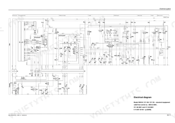
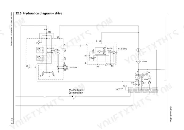
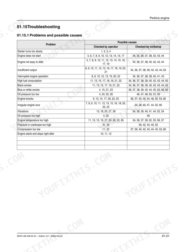
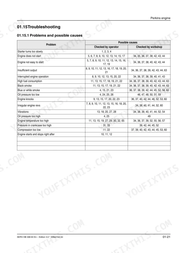
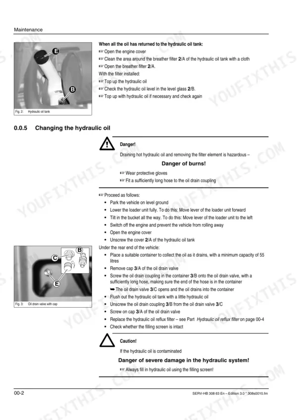


This is the Gehl Service Manual for the 418 and 418T wheel loaders, form number 50940186, built around the Perkins 704-30 diesel engine. Its 200 pages are organized by system, covering controls, specifications, maintenance, the Perkins engine, hydrostatic drive, axles, brakes, steering, the electrical system, the hydraulic system and heating.
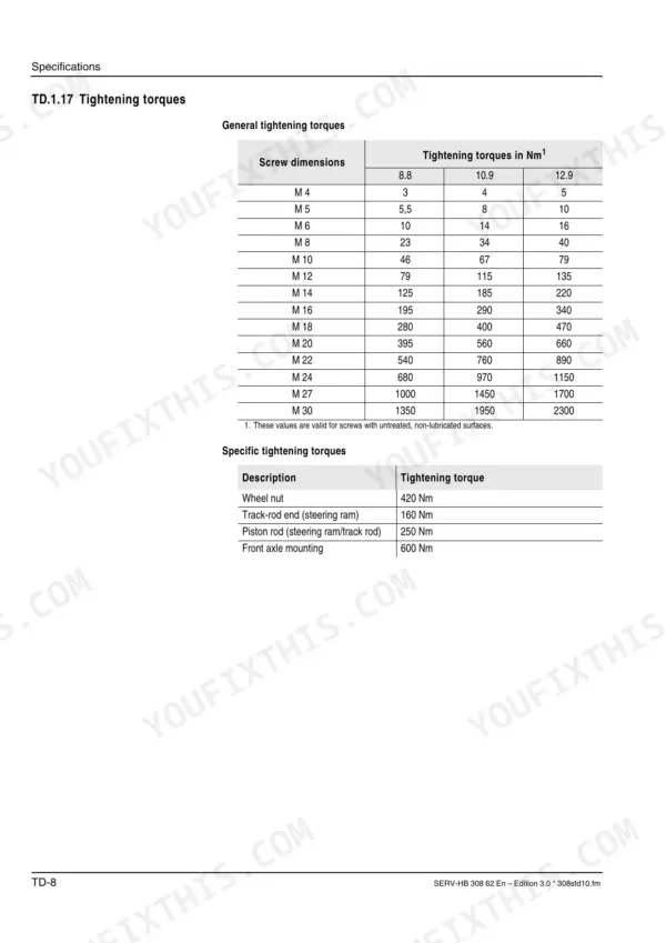
The specification tables give engine data, capacities, service pressures and tightening torques, including the 420 Nm wheel-nut torque and the full Perkins engine torque list. Deeper chapters detail the hydrostatic pump and variable-displacement motor, the front and rear axles with planetary drives and self-locking differentials, the steering rams and wheel synchronization, the control valve and the lifting and dumping circuits, and the SUSMIC electrical diagnostics with its table of errors. Delivered as a searchable, printable PDF, it downloads instantly for the shop computer or a tablet at the machine.
What's Inside This Manual
| System | Pages | Key Topics |
|---|---|---|
| Machine Specifications | 3-21 | Frame, Engine, Power Train, Axles and Differentials, Brakes, Steering, Hydraulic System, Lubricants and Fluids |
| Maintenance & Service Schedule | 22-37 | Hydraulic Oil Level Check, Hydraulic Oil Change, Hydraulic Oil Reflux Filter, Gearboxes and Axles, Rear Axle Transfer Gearbox, Front and Rear Axle Differentials, Engine Fluids and Lubricants, Maintenance Plan and Records |
| Engine (Perkins) | 38-61 | Perkins Engine Specifications, Tightening Torques, Crankcase Breather, Valve Cover, Rocker-Arm Shaft |
| Hydrostatic Drive & Susmic Diagnostics | 62-100 | Hydraulic Pump, Variable Displacement Motor, Hydraulic Oil Circuit, Nfpe System (Susmic), Connection Diagram, Table of Errors, Susmic-Dia 1 Diagnostics, Sensor Setup Procedure |
| Axles & Final Drives | 101-109 | Front Axle, Rear Axle, Axle Body, Planetary Drive, Self-Locking Differential, Transfer Gearbox |
| Brakes | 110-115 | Service Brake, Parking Brake, Brake Circuit, Inching Potentiometer, Parking Brake Lever Adjustment, Pressure Switch |
| Steering | 116-128 | Steering Circuit, Steering Rams, Sevostat, Wheel Synchronization, Steering Stop Adjustment, Steering Diagram |
| Electrical System & Wiring Diagrams | 129-147 | Control Valve Actuation, Drive Switch Wiring, Control Lever, 3rd Control Circuit, Working Headlights, Interior Light, Spare Fuse, Wiring Diagrams |
| Hydraulic System & Diagrams | 148-172 | Lift Ram Circuit, Tilt Ram Circuit, Control Valve, Hydraulic Oil Tank, Suction and Reflux Filter, Main Pressure Relief Valve, Lifting and Dumping Circuit, Anticavitation Valve |
| Cab Heating | 173-175 | Heating Circuit, Heater Nozzle, Filter, Control Slide, Front Window Wiper Cover |
| Controls & Operator Instruments | 176-200 | Cab Overview, Instrument Panel, Multifunctional Lever, Control Panel, Side Console, Rocker Switch, Telltale Lights |
Quick Reference Specifications
| Specification | Value | Page |
|---|---|---|
| Wheel nut torque | 420 Nm | p. 13 |
| Track-rod end (steering ram) torque | 160 Nm | p. 13 |
| Piston rod (steering ram/track rod) torque | 250 Nm | p. 20 |
| Front axle mounting torque | 600 Nm | p. 20 |
| Engine Displacement | 2955 cm³ | p. 6 |
| Engine Oil Capacity | 7 ltr. | p. 31 |
| Hydraulic Oil Tank Capacity | 50 l | p. 31 |
| Fuel Tank Capacity | 60 ltr. | p. 31 |
| Wheel Nut Tightening Torque | 420 Nm | p. 13 |
| Engine Valve Tip Clearance (cold) | 0.35 mm | p. 6 |
| Boost Pump Charging/Boost Pressure | 20 bar | p. 7 |
| Max. Service Pressure (Work Hydraulics) | 210+10 bar | p. 8 |


