


This is the factory service manual for the Mustang ML52 wheel loader, covering the 520 and 620 machines (models 303 58 and 304 59) built on Perkins 1004-4 diesel engines, including the 1004-4 LR, 1004-4 HR, and low-emission 1004-42. Published as part number 50940190, it runs 194 pages.Coverage includes engine service, the hydrostatic drive and hydraulic circuit, the ZF APL-R 735 planetary front axle, brakes, the steering system, and the complete electrical system with wiring harness diagrams and fuse sizes. Specifications, maintenance kits, and torque values run throughout.With this PDF you can adjust valve clearance, pressure-test the hydrostatic and work hydraulics, synchronize and bleed the steering, service the axles and brakes, and trace wiring faults against the diagrams. It gives an owner or independent mechanic dealer-level detail for these loaders.
What's Inside This Mustang ML52 Manual
| System | Pages | Key Topics |
|---|---|---|
| General & Service Materials | 3 | Specifications / Controls, Servicing Material, Sealing Kits, Lubricants, Engine, Fuel Lines, Cooling, Frame |
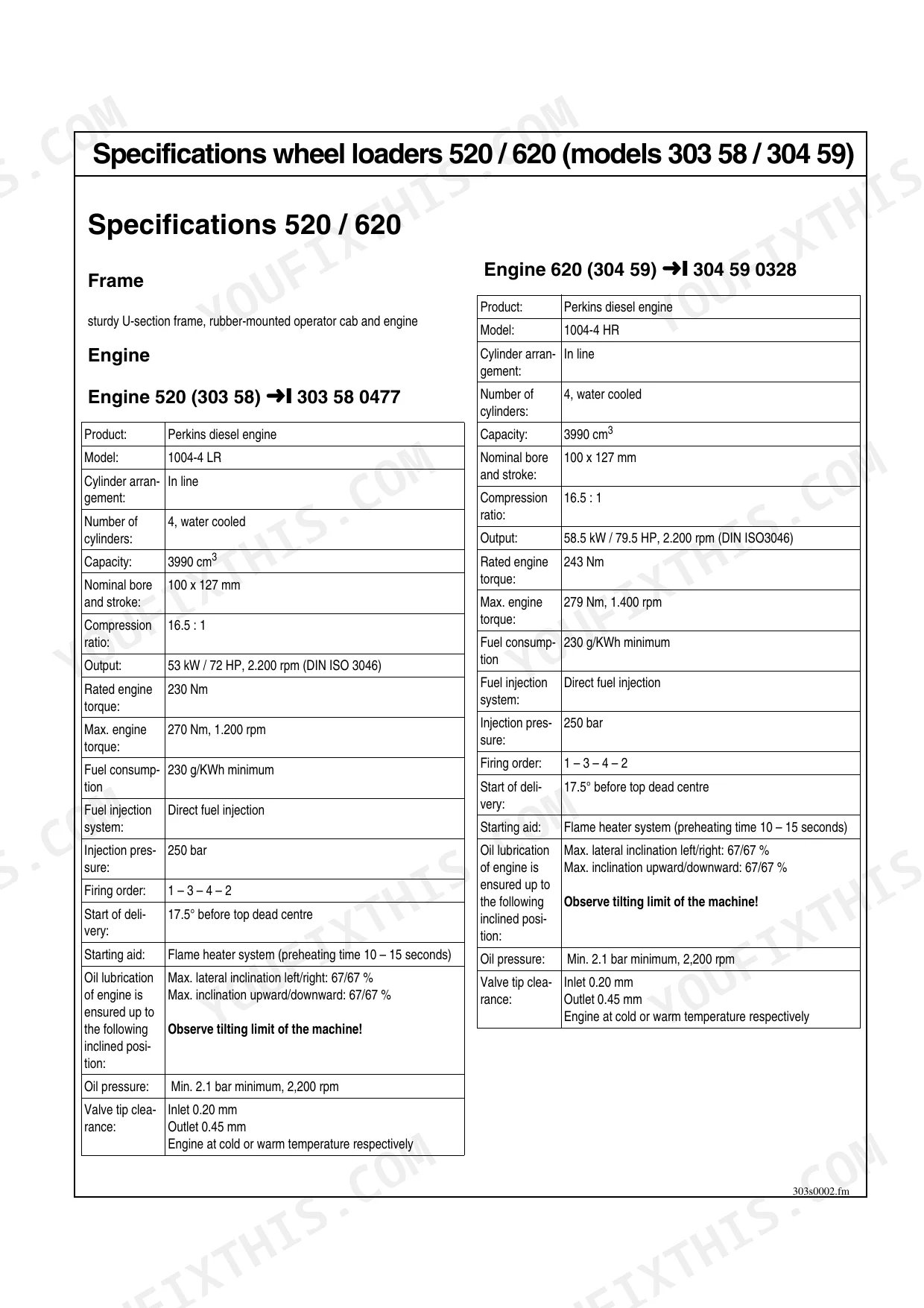
| Specifications (520 / 620) | 4-16 | Specifications Controls, Specifications Wheel Loaders 520 / 620, Frame, Engine, Engine 520, Engine 620, Low-Emission Engine 520 |
| Maintenance Kits | 17-19 | Service Kit for “1st Inspection”, Maintenance Kit for Maintenance Plan “B”; “C” and “2nd Inspection”, Maintenance Kit for Maintenance Plan “D” |
| Maintenance & Lubrication | 20-21 | Oil and Filter Changes, Inspection Work, Lubrication, Functional Check, Leakage Check |
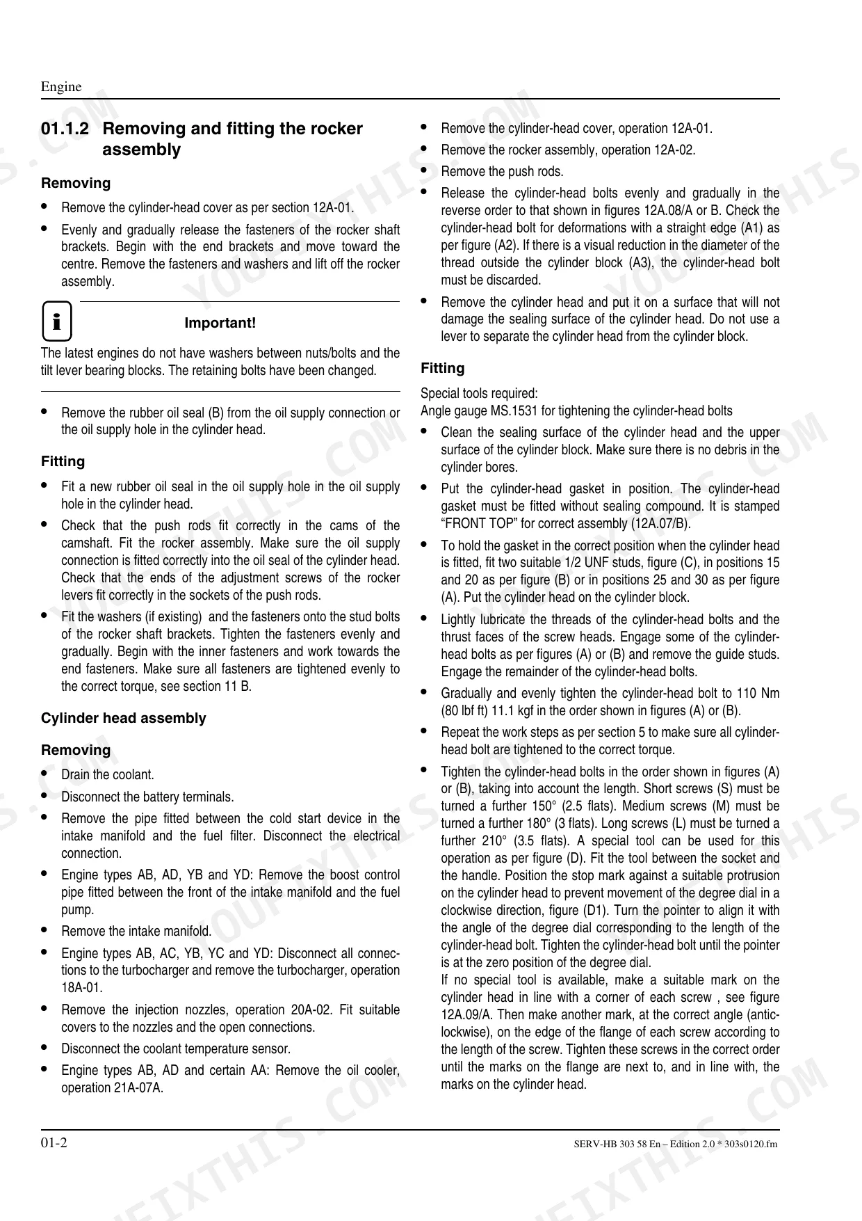
| Engine | 22-32 | Specifications, Engine 520, Engine 620, Valve Tip Clearance (Checking and Adjusting, Four Cylinder Engines), Removing and Fitting the Rocker Assembly |
| Fuel System | 33-34 | Group 08, Fuel Lines, Fuel Feed System 520 / 620 Wheel Loaders |
| Cooling System | 35-36 | Group 15, Cooling, Cooling System 520 / 620 Wheel Loaders |
| Frame | 37-38 | Group 20, Vehicle Frame Wheel Loaders 520 / 620 |
| Hydrostatic Drive | 39-88 | Hydrostatic Drive Wheel Loaders 520 / 620, Hydraulic Circuit Wheel Loaders 520 / 620, Temperature Controller 520/620 |
| Front Axle | 89-94 | Front Axle (Specifications and Set Values for Zf Apl-R 735 Planetary Steering Axle, Lubrication and Service Instructions) |
| Brakes | 95-98 | Group 24, Brake System 520 / 620 Wheel Loaders, Brake Diagram 520 / 620 Wheel Loaders, Hydr Fixed-Calliper Brake 520 / 620 Wheel Loaders |
| Rear Axle | 99-101 | Group 26, High Speed 520 / 620 Wheel Loaders |
| Steering | 102-106 | Specifications, Synchronising the Steering, Bleeding the Steering System |
| Electrical System | 107-139 | Fundamentals (Ohm's Law; Power, Measuring Equipment, Measuring Methods, Terminal Description, Pin Interface - Cab / Frame, 20 Series) |
| Wiring Harness & Electronics | 140-149 | Electronics Box Models 300 55/301 56/302 57/303 58/304 59, Cable Assignment, Main Wiring Harness Frame 0 38 330 00 10, Assignment Table 21 Pole Interface, Wiring Harness |
| Wiring Harness (Instrument Panel) | 150-155 | Electrical System Overview, Wiring Harness Instrument Panel 0 00 080 39 64, Wiring Harness Details |
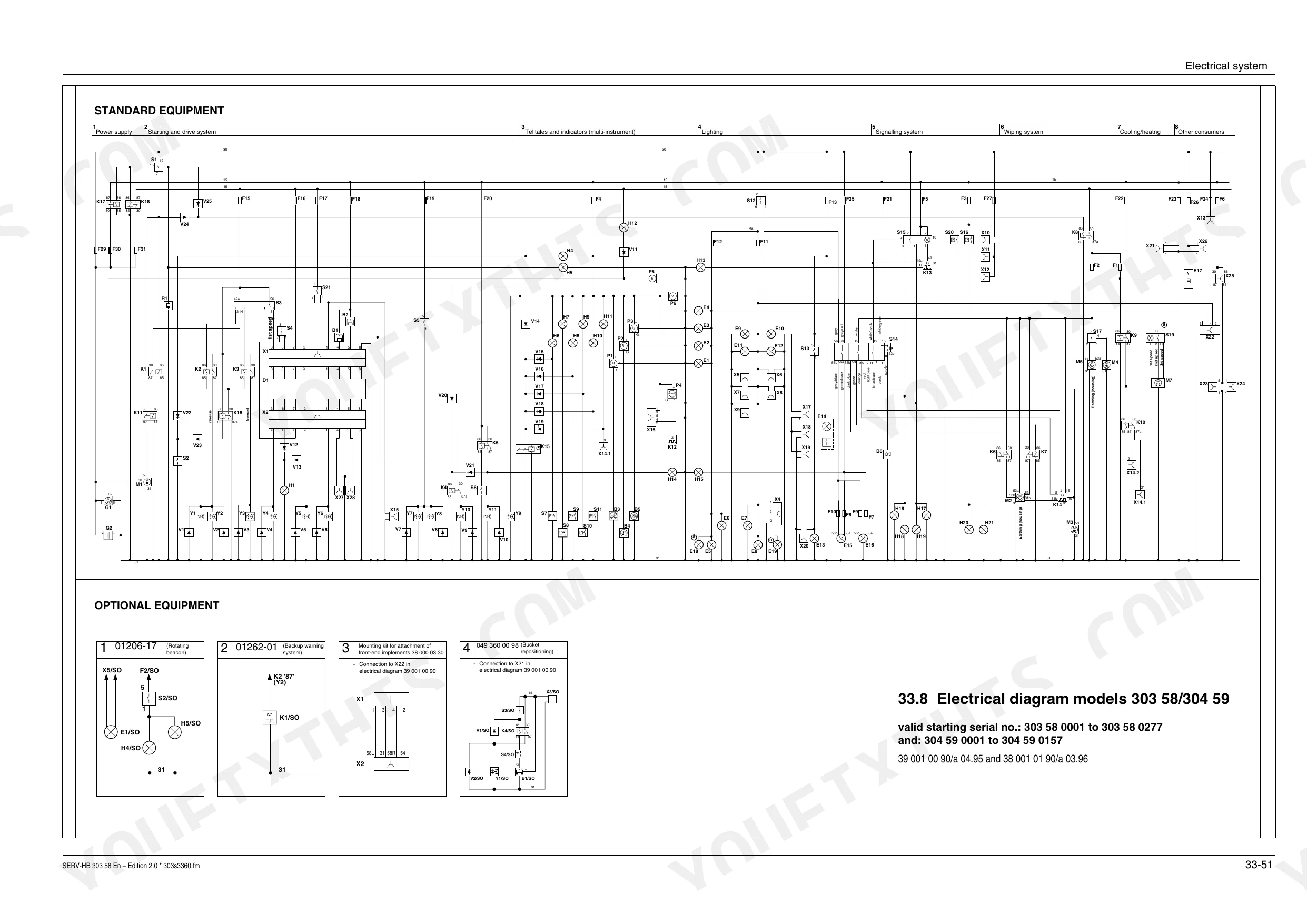
| Electrical Diagrams | 156-163 | Wiring Harness Instrument Panel 0 00 080 39 64, Ref No Description Section, Fuse Sizes, Electrical Diagram Models 303 58/304 59 |
| Cab | 164-165 | Group 34, Removing the Front Wiper Motor 520 / 620 Wheel Loaders |
| Hydraulic System | 166-184 | Group 36, Hydraulic System 520 / 620 Wheel Loaders, Work Hydraulics 520 / 620 Wheel Loaders, Hydraulic Tank 520 / 620 Wheel Loaders |
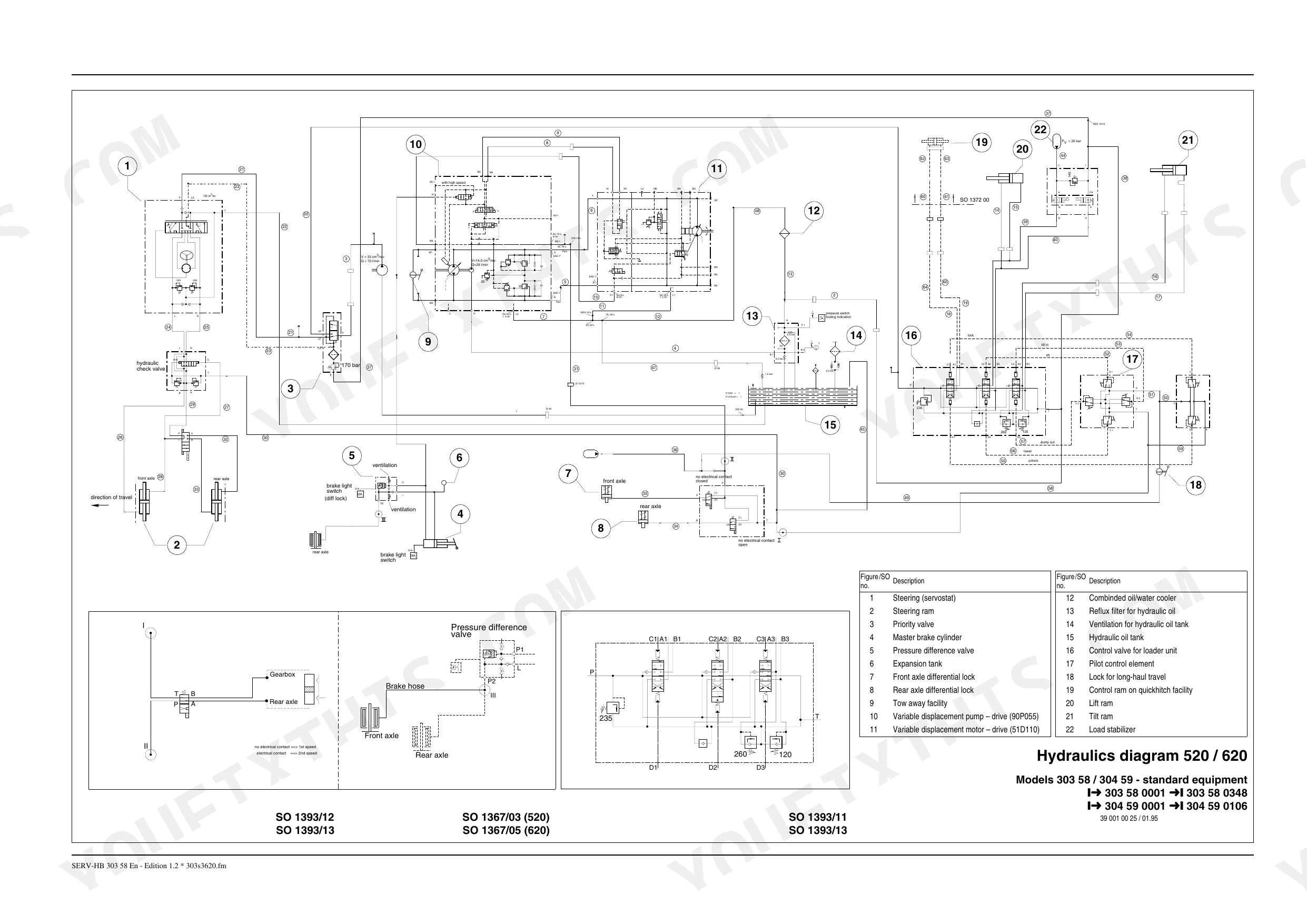
| Hydraulic Diagrams | 185-188 | Hydraulics Diagram 520 / 620, Notes |
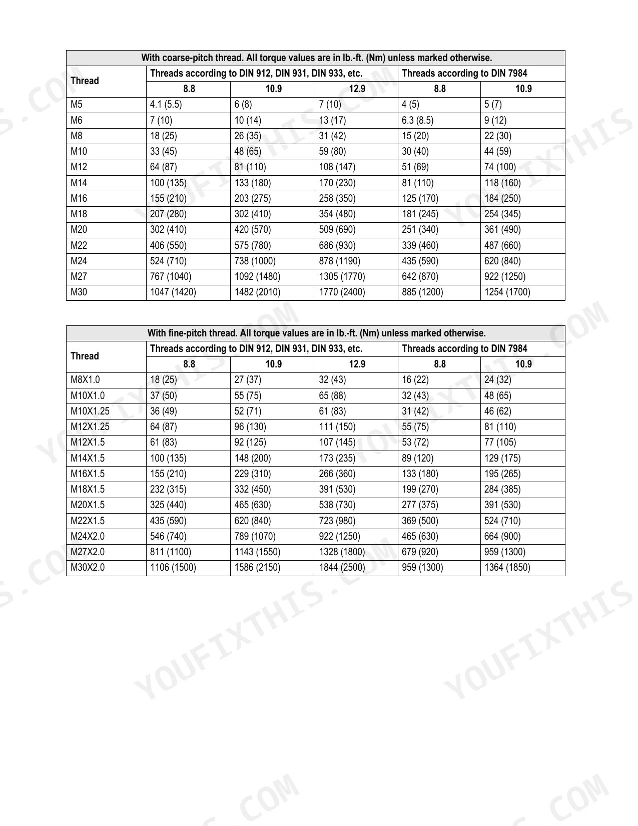
| Cab Heating & Torque Specs | 189-194 | Group 41, Cab Heating, Heating 520 / 620 Wheel Loaders, Torque Specifications, Hydraulic Fittings with Various Seals, With Coarse-Pitch Thread, With Fine-Pitch Thread |
Quick Reference Specifications
| Specification | Value | Page |
|---|---|---|
| Wheel nut torque | 420 ±20 Nm | p. 10 |
| Hydraulic oil filter insert replacement interval | every 12 months or 1200 service hours | p. 21 |
| Air filter insert replacement interval | every 12 months or 1200 service hours | p. 21 |
| Fuel filter replacement interval | every 50 hours | p. 21 |
| Engine coolant capacity | About 15 ltr. | p. 18 |
| Thermostat minimum opening distance | 9 mm | p. 29 |
| Battery voltage and capacity | 12 V, 100 Ah | p. 9 |
| Tire pressure (front) for 14.5-20 MPT E91-2 10PR 132 E | 2.25* bar | p. 9 |
| Maximum hydraulic oil temperature | 85°C | p. 70 |
| Main pressure relief valve pressure (work hydraulics) | 235 bar | p. 73 |
| Lift ram piston screw torque | 1000 Nm | p. 183 |
| Engine 520 Output | 53 kW / 72 HP, 2.200 rpm | p. 5 |
Mustang ML52 Common Problems This Manual Covers
Engine overheating under load
Low coolant, a clogged radiator, or restricted airflow lets the engine and hydraulic oil run hot under load. The Cooling section covers the 520 and 620 cooling system, and the manual caps hydraulic oil temperature at 85 degrees C.
Manual Section: Cooling p. 35Slow or weak hydraulic lift and bucket
Weak or erratic lifting points to low or contaminated fluid, leaks, or a relief valve out of spec. The Hydraulic System section covers the work hydraulics and tank, with the main pressure relief valve set at 235 bar.
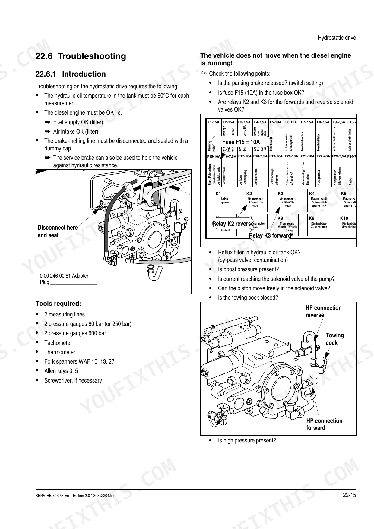
Manual Section: Hydraulic System p. 166Weak hydrostatic drive
A machine that revs high but will not move with authority usually has hydrostatic pump or motor wear or low fluid. The Hydrostatic Drive section covers the drive, hydraulic circuit, and temperature controller for the 520 and 620.
Manual Section: Hydrostatic Drive p. 39Hard starting or power loss
Clogged fuel filters or poor fuel delivery cause hard starting and lost power. The Fuel Lines section covers the fuel feed system for the 520 and 620 wheel loaders.
Manual Section: Fuel Lines p. 33Electrical faults or no-start
A weak battery, corroded terminals, or a damaged harness leave the loader with intermittent lights or a no-start. The Electrical System section covers fundamentals, terminal descriptions, and the cab and frame interfaces.
Manual Section: Electrical System p. 107Sluggish or unresponsive steering
A wheel loader steers on hydraulics, so slow or wandering steering points to air in the system or a circuit fault. The Steering System section covers synchronizing the steering and bleeding the steering system.
Manual Section: Steering System p. 102Frequently Asked Questions
Which machines does this manual cover?
It covers the Mustang ML52 wheel loader in the 520 and 620 configurations (models 303 58 and 304 59), built on Perkins 1004-4 diesel engines. Published as part number 50940190.
Does it give the wheel nut torque?
Yes. The Specifications Controls section lists tightening torques, and the wheel nut torque is given as 420 plus or minus 20 Nm. p. 4
Does it cover the hydrostatic drive?
Yes. The Hydrostatic Drive section covers the hydrostatic drive, hydraulic circuit, and temperature controller for both the 520 and 620 wheel loaders. p. 39
Are wiring diagrams included?
Yes. The Electrical System section covers the electrical fundamentals and, along with the following harness sections, provides the wiring harness diagrams, cable assignments, and fuse sizes. p. 107
How quickly can I access this manual after buying?
Download starts the moment payment clears. The full 194-page searchable Service Manual is yours to open on a laptop, tablet, or phone right in the shop.
Is this Mustang ML52 Service Manual printable?
Yes, print as many copies as you want, with no restrictions. Plenty of mechanics print just the section they need and carry it to the shop floor.
Does this Mustang ML52 manual include hydraulic schematics?
Yes. The manual includes hydraulic circuit diagrams, system schematics, and component specifications with pressure ratings.


Reviews
There are no reviews yet.