


This is the factory Perkins Workshop Manual for the V8.510, V8.540 and TV8.540 diesel engines, the 8-cylinder units Perkins built for vehicle and industrial use. It covers all three variants in one 136-page book, with the information applying to every type unless a procedure is called out for a specific model.Inside you get full technical data, torque figures and running clearances, plus step-by-step overhaul procedures for the cylinder head, pistons and connecting rods, crankshaft and main bearings, timing gear, and the lubricating, cooling and fuel systems. The turbocharged TV8.540 gets its own turbocharger section.Whether you are setting valve clearances, renewing cylinder liners, or rebuilding the engine from the block up, the exact specifications and sequences are here. Delivered as an instant PDF download you can read on any device or print for the workbench.
What's Inside This Perkins V8.510, V8.540, TV8.540 Manual
| System | Pages | Key Topics |
|---|---|---|
| Engine Views | 7-10 | View of Top Front of Naturally Aspirated Engine, View of Rear Left Hand Side of Naturally Aspirated Engine, View of Rear Right Hand Side of Turbocharged Engine |
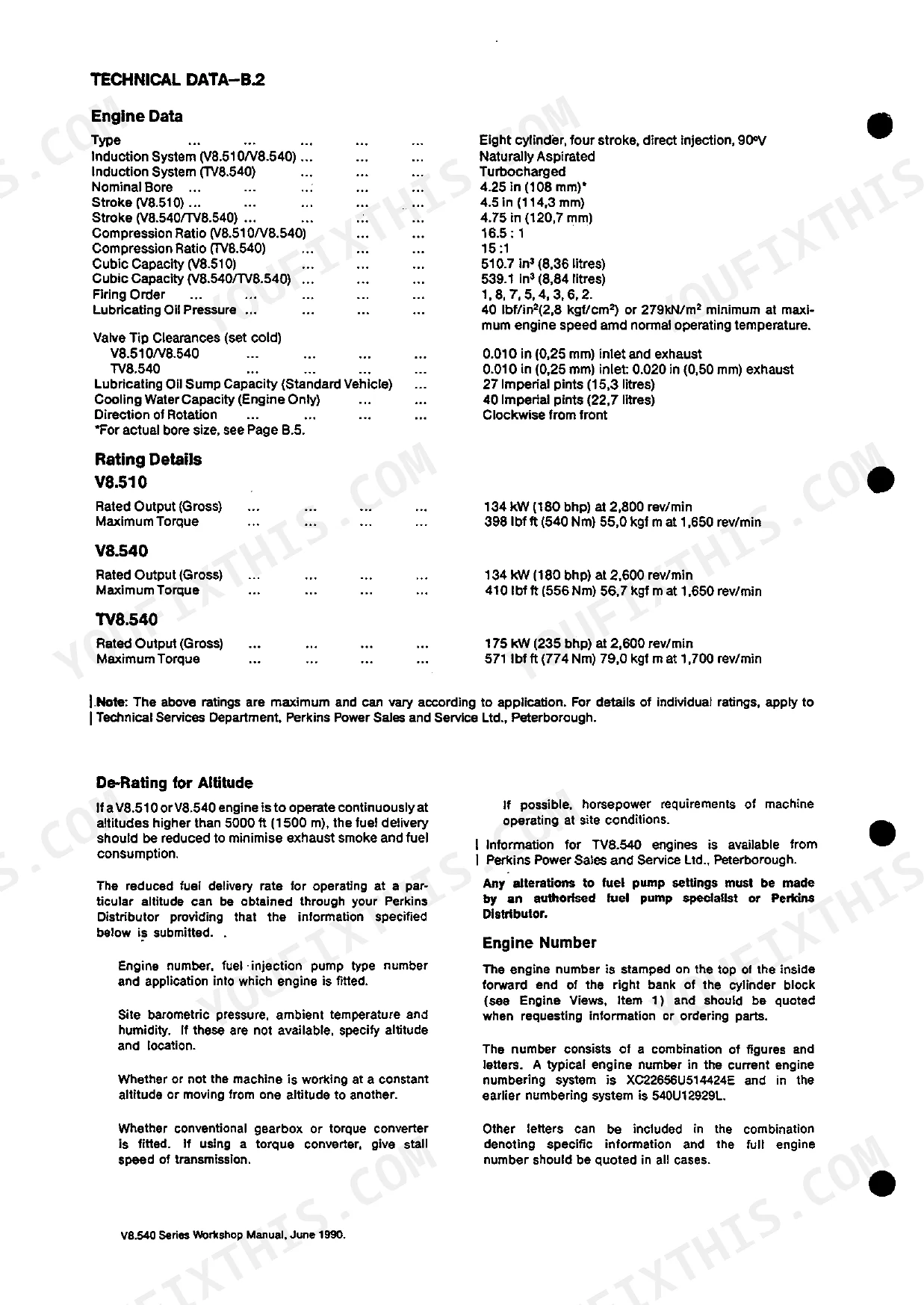
| Technical Data | 11-28 | Engine Data, Rating Details, De-Rating for Altitude, Engine Number, Recommended Torque Tensions, Cylinder Numbering, Engine Weights, Data and Dimensions |
| Operating and Maintenance | 29-34 | Starting the Engine, Starting a Warm Engine, Starting a Cold Engine, To Check the Cav in Line Pump Excess Fuel Device, Notes on Heat Start, Extreme Cold Weather Starting Aid |
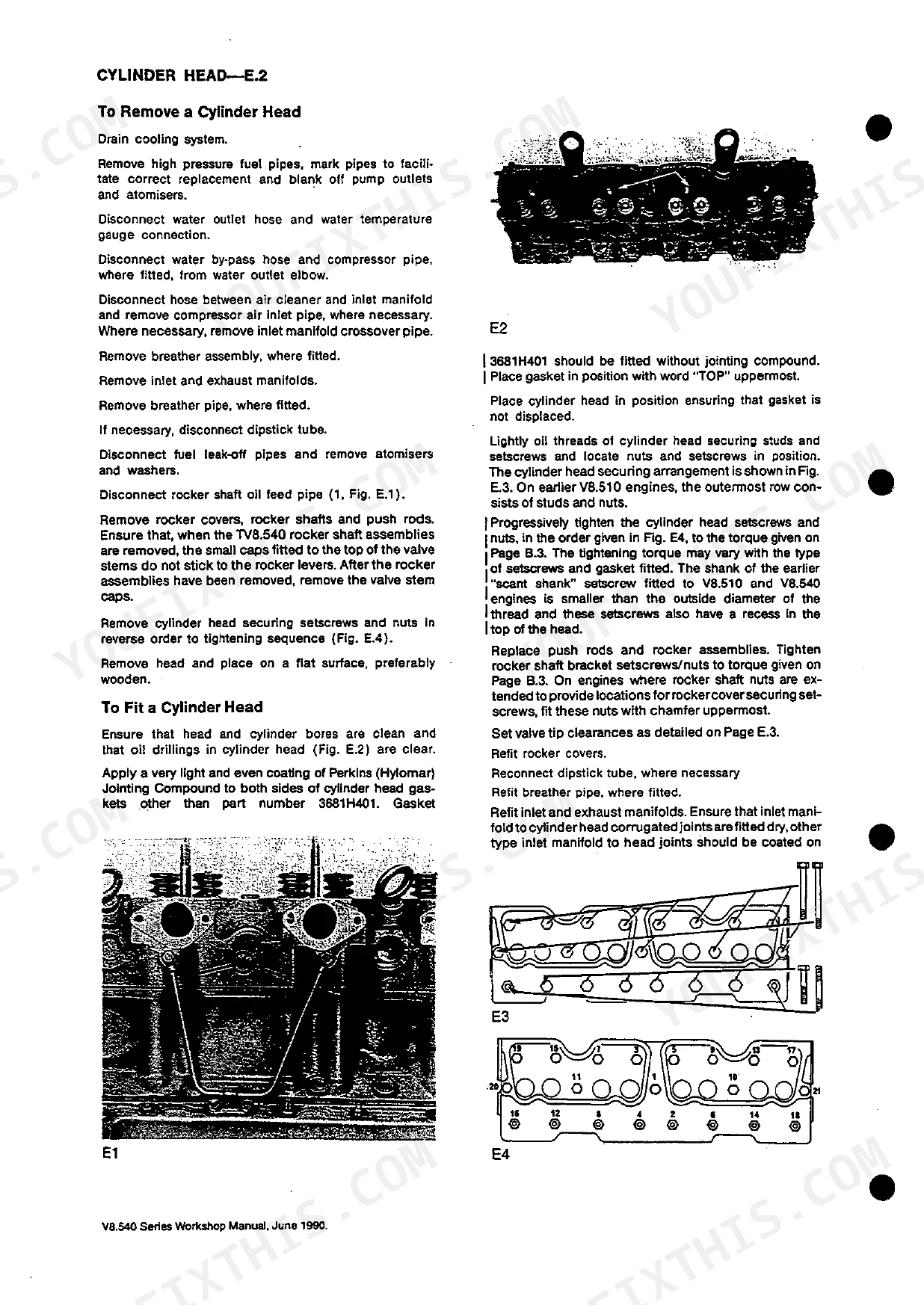
| Cylinder Head | 37-46 | To Remove a Cylinder Head, To Fit a Cylinder Head, To Check or Adjust Valve Tip Clearances, To Fit High Pressure Fuel Pipes, Valve Assemblies, To Remove Valves, To Fit Valves |
| Pistons and Connecting Rods | 47-52 | General, To Remove Piston and Rings From Connecting Rod, To Remove Piston and Rod Assembly, Inspection, To Renew Small End Bush, To Check Piston Ring Gaps |
| Cylinder Block and Liners | 53-55 | Cylinder Block, Cylinder Liners, To Remove and Fit Cylinder Liner, Oversize Cylinder Liners |
| Crankshaft and Main Bearings | 56-64 | General, Crankshaft End Float, To Change Thrust Washers, To Remove Crankshaft, To Fit Crankshaft, TV8.540 and Later V8.540 Crankshaft Pulley Clamping Arrangement |
| Timing Case and Drive | 65-72 | To Remove Timing Case, To Refit Timing Case, To Remove and Refit Upper Half Timing Case, To Renew Front Oil Seal, To Remove Camshaft Gear, To Fit Camshaft Gear, To Remove Camshaft |
| Timing | 73-79 | Gear Timing Marks, Crankshaft Timing Arrangement, To Position No. 1 Piston to T.D.C. Compression Stroke, Checking Valve Timing |
| Lubricating System | 80-91 | General, Oil Strainer, Oil Filter, To Renew Earlier Lubricating Oil Filter Elements, To Renew Disposable Canister Oil Filter Elements, To Remove Oil Cooler, Oil Cooler |
| Cooling System | 92-97 | General, Fan Belts, Tensioner Pulley, Thermostats, Water Pump, Piston Cooling Jets |
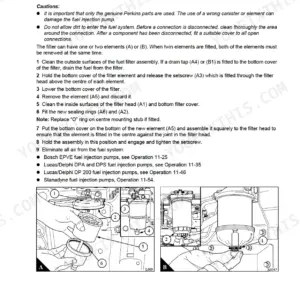
| Fuel System | 98-108 | Fuel Filter, To Renew Single Fuel Filter Element, To Renew Twin Fuel Filter Elements, To Renew Screw-On Canister Fuel Fitter Elements., Fuel Lift Pump |
| Flywheel and Flywheel Housing | 109-110 | Flywheel, Flywheel Ring Gear, Flywheel Housing |
| Compressor/Auxiliary Drive | 111-117 | Sc 12 Compressor, To Remove Compressor, To Fit Compressor, To Fit Compressor Types Pcga 625/5 Onwards, To Dismantle Compressor and Auxiliary Drive, Overhaul |
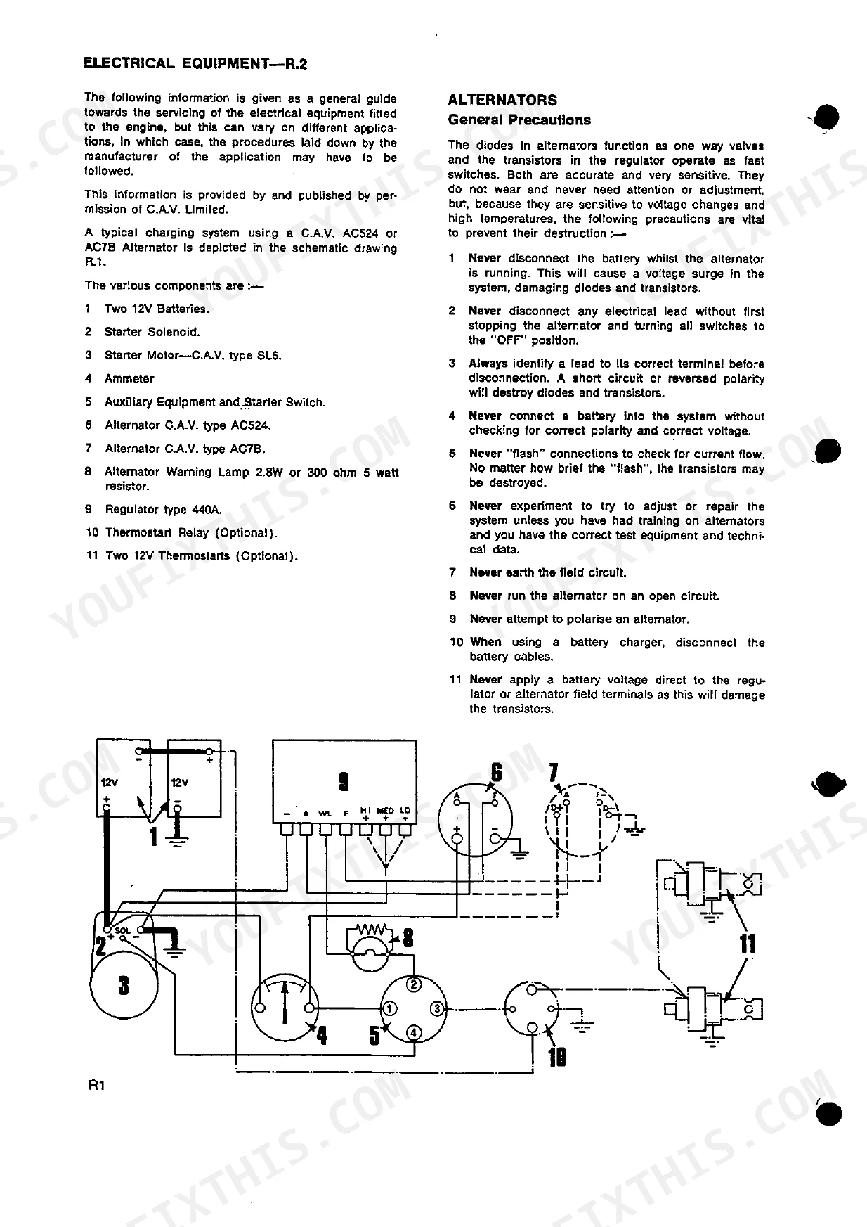
| Electrical System | 118-121 | Alternators, Testing Procedures with AC5 or AC7B Alternator System Fitted to Application, Checking Operation of a Newly Wired System, Test Equipment Required, Test Procedure |
| Turbocharger | 122-127 | To Clean Impeller, To Remove Turbocharger, To Fit Turbocharger, To Check Bearings, To Dismantle Turbocharger, Inspection |
| Fuel and Lubricating Oil Specifications | 128 | Fuel Specification, Lubricating Oil Specification, Recommended Sae Viscosity Grades |
| Service Facilities | 129 | Service Publications, Use Only Genuine Perkins Parts, Service Instruction |
| Approved Service Tools | 130-133 | Tools on Page 130 (Valve Guide Remover and Replacer, Adaptor for PD.1D, Short Valve Guide Replacer/Adaptor, Piston Ring Squeezer, Piston Height and Valve Height Gauge, Universal Timing Gauge) |
Quick Reference Specifications
| Specification | Value | Page |
|---|---|---|
| V8.540/TV8.540 | ||
| Big End Setscrews | 105 lbf ft (142 Nm) 14,5 kgf m | p. 13 |
| Big End Setscrews torque | 105 lbf ft (142 Nm) 14,5 kgf m | p. 13 |
| V8.540 | ||
| Cylinder Head (Straight Shank) Setscrews/Nuts with washers and gasket 3681H401 | 155 lbf ft (210 Nm) 21,4 kgf m | p. 13 |
| Cylinder Head Setscrews/Nuts torque | 155 lbf ft (210 Nm) 21,4 kgf m | p. 13 |
| All Models | ||
| Maximum permissible longitudinal bow of cylinder head | 0.008 in (0,20 mm) | p. 42 |
| Interference Fit of Production Liner in Cylinder Block Parent Bore | 0.001/0.003 in (0,025/0.076 mm) | p. 15 |
| Max. Permissible Worn Inside Diameter of Liner - New Rings Fitted | 4.255 in (108,08 mm) | p. 15 |
| Atomiser Securing Nuts torque | 12 lbf ft (16 Nm) 1,7 kgf m | p. 13 |
| Atomisers (Code Letters VA and VB) Working Pressure | 170 atmospheres (176 kgf/cm²) 2500 lbf/in² | p. 26 |
| Main Bearing Cap Setscrews torque | 210 lbf ft (285 Nm) 29,0 kgf m | p. 13 |
| DP15 Pump | ||
| Fuel Injection Pump Gear Capscrews (DP 15 Pump) torque | 35 lbf ft (47 Nm) 4,8 kgf m | p. 13 |
| V8.540 and AV8.540 Engines | ||
| Spill Timing Position B.T.D.C. | 28° | p. 25 |
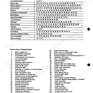
Perkins V8.510, V8.540, TV8.540 Common Problems This Manual Covers
Overheating between cylinder banks
Owners report uneven cooling on these V8 engines, with one bank running hotter than the other and pushing coolant temperatures up under load. The Cooling System section covers the water pump, thermostats and fan belts you check first when temperatures climb.
Manual Section: Cooling System p. 92Head gasket failure and coolant loss
Sustained overheating and thermal stress lead to blown head gaskets and repeated coolant loss on the V8.510 and V8.540. The Cylinder Head section gives the removal, refit and clamping procedures needed to renew a gasket correctly.
Manual Section: Cylinder Head p. 37Cracked or worn cylinder liners
Thermal stress and vibration in the V8 layout can crack sleeves or wear liner bores past their limit. The Cylinder Block and Liners section covers removing, fitting and sizing production and oversize liners.
Manual Section: Cylinder Block and Liners p. 53Rough running and black smoke
Erratic fuel delivery, surging and black smoke are common complaints tied to injection pump and fuel system faults on this engine family. The Fuel System section covers the filters, lift pump and pump service that address unstable fuelling.
Manual Section: Fuel System p. 98Main and big-end bearing wear
Lubrication limits and load-related stress cause bearing wear or failure over time, often with falling oil pressure as the first sign. The Crankshaft and Main Bearings section covers thrust washer changes, crankshaft removal and refit.
Manual Section: Crankshaft and Main Bearings p. 56Boost loss on the TV8.540
Turbocharged TV8.540 engines lose power when the turbocharger fouls, wears its bearings or leaks. The Turbocharger section covers cleaning the impeller, checking bearings, and removing and refitting the unit.
Manual Section: Turbocharger p. 122Frequently Asked Questions
Which engines does this manual cover?
It covers the Perkins V8.510, V8.540 and TV8.540 diesel engines in one book, with the information applying to all three unless a procedure notes a specific type. Note it does not cover V8.510 engines built before engine number 510U2000.
Does it include torque figures for the engine?
Yes. The Technical Data section lists the recommended torque tensions, including cylinder head, main bearing cap and big-end setscrew values, along with running clearances and dimensions for all three engine types. p. 11
Can I set the valve tip clearances with this manual?
Yes. The Cylinder Head section explains how to check or adjust valve tip clearances and gives the cold setting figure, along with removing and fitting the cylinder head and valve assemblies. p. 37
Does it cover turbocharger service on the TV8.540?
Yes. The Turbocharger section covers cleaning the impeller, removing and fitting the turbocharger, checking bearings, and dismantling and inspecting the unit on the turbocharged TV8.540. p. 122
How will I receive this Perkins V8.510, V8.540, TV8.540 Workshop Manual?
This is a 136-page searchable PDF ready for immediate download. It works on any device: pull it up on your phone while you're under the hood. No shipping, no waiting.
Am I able to print pages from this Perkins V8.510, V8.540, TV8.540 manual?
The PDF is DRM-free, so print whatever sections you want to take out to the shop. Standard letter or A4 paper works.
Are hydraulic system diagrams in this Perkins V8.510, V8.540, TV8.540 manual?
A lubricating oil flow diagram is included, showing the internal oil circuits and component locations for the Perkins V8.510, V8.540, TV8.540.
Reviews
There are no reviews yet.