


Part of the Yanmar Parts Manuals.
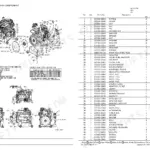
All 40 pages of this Yanmar Parts Catalog (OEM #Y00R5650) are built for one job: putting the correct part number in your hands for the 4TNV84T-DSA, DSA2, DSA3, and GGE diesel engines. Inside, exploded-view diagrams cover every major assembly: cylinder block, crankshaft and piston, camshaft and driving gear, turbocharger, fuel injection pump, cooling water circuit, and lube oil system. Variant-specific sections split DSA/DSA2/DSA3 from GGE configurations on gear housing, fuel injection pumps, governor inner parts, and starting motor, so your lookup always lands on the right assembly. Pull up the turbocharger section and you'll find the RHF4 turbine assembly with OEM part numbers traced down to individual gaskets and studs. Wrong part, two-day wait, machine still down. Bookmarked by system and keyword-searchable: open it on your phone, find the number, and order right the first time.
What's Inside This Yanmar 4TNV84T / 4TNV88 Series Parts Manual
| System | Pages | Key Topics |
|---|---|---|
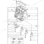
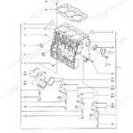
| Engine Section | 2-2 | Cylinder Block, Gear Housing 4TNV84T-Dsa, DSA2, DSA3, Gear Housing 4TNV84T-Gge, Flywheel Housing & Oil Sump, Cylinder Head & Bonnet, Suction Manifold, Exhaust Manifold, Camshaft & Driving Gear |
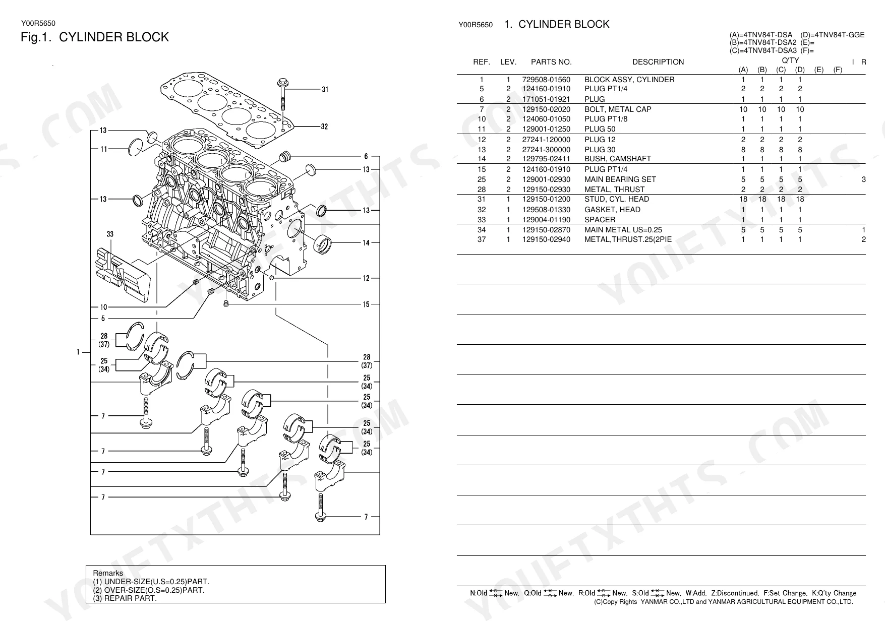
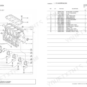
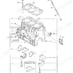
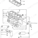
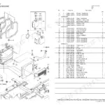
| Cylinder Block | 3-3 | Exploded View Diagram, Part Numbers, Assembly Specifications |
| Gear Housing | 4-4 | Exploded View Diagram, Part Numbers, Assembly Specifications |
| Gear Housing | 5-5 | Exploded View Diagram, Part Numbers, Assembly Specifications |
| Flywheel Housing & Oil Sump | 6-6 | Exploded View Diagram, Part Numbers, Assembly Specifications |
| Cylinder Head & Bonnet | 7-8 | Exploded View Diagram, Part Numbers, Continuation |
| Suction Manifold | 9-9 | Exploded View Diagram, Part Numbers, Assembly Specifications |
| Exhaust Manifold | 10-10 | Exploded View Diagram, Part Numbers, Assembly Specifications |
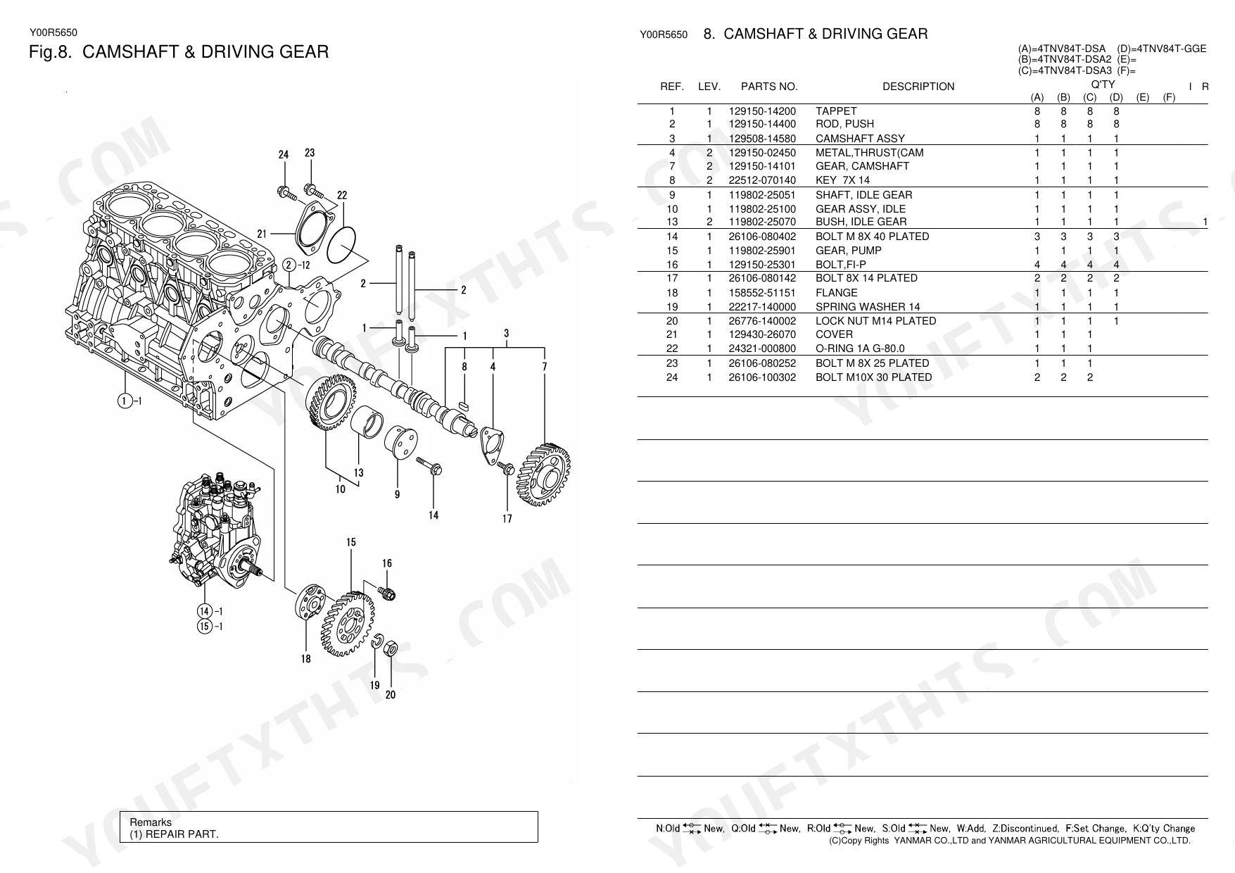
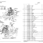
| Camshaft & Driving Gear | 11-11 | Exploded View Diagram, Part Numbers, Assembly Specifications |
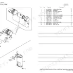
| Turbine | 12-12 | Exploded View Diagram, Part Numbers, Assembly Specifications |
| Crankshaft & Piston | 13-13 | Exploded View Diagram, Part Numbers, Assembly Specifications |
| Lub.oil System | 14-14 | Parts List, Remarks |
| Lub Oil Line | 15-15 | Exploded View Diagram, Part Numbers, Assembly Specifications |
| Cooling Water System | 16-16 | Exploded View Diagram, Part Numbers, Assembly Specifications |
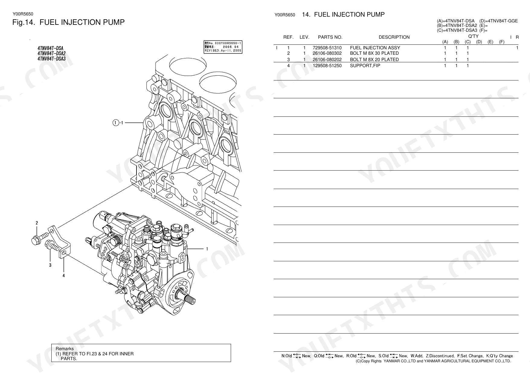
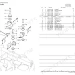
| Fuel Injection Pump | 17-17 | Exploded View Diagram, Part Numbers, Assembly Specifications |
| Fuel Injection Pump | 18-18 | Exploded View Diagram, Part Numbers, Assembly Specifications |
| Fuel Injection Valve | 19-19 | Exploded View Diagram, Part Numbers, Assembly Specifications |
| Fuel Injection Valve | 20-20 | Exploded View Diagram, Part Numbers, Assembly Specifications |
| Fuel Line | 21-21 | Loose Parts |
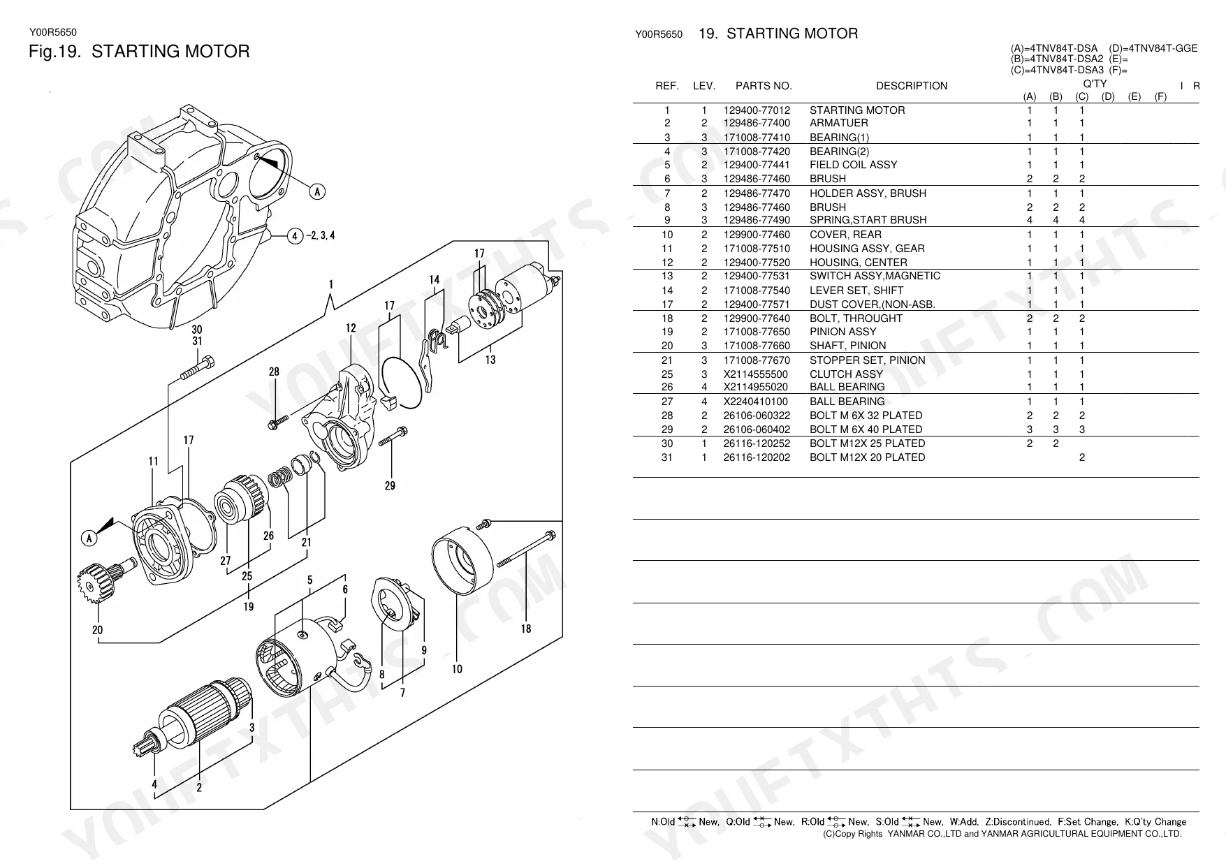
| Starting Motor | 22-22 | Exploded View Diagram, Part Numbers, Assembly Specifications |
| Starting Motor | 23-23 | Exploded View Diagram, Part Numbers, Assembly Specifications |
| Generator | 24-24 | Loose Parts |
| Gasket Set | 25-25 | Optional Parts |
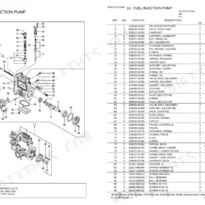
| Fuel Injection Pump (Inner Parts) | 26-27 | Exploded View Diagram, Part Numbers, Continuation |
| Governor (Inner Parts) | 28-28 | Parts List, Remarks |
| Fuel Injection Pump (Inner Parts) | 29-31 | Parts List Continuation, Remarks Continuation |
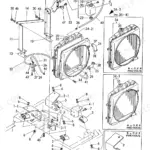
| Optional Kit | 32-40 | Engine Foot, Air Cleaner, Exhaust Manifold, Silencer & Tall Pipe, Ho-P Driving, Oil Coller, Radiator, Electric Parts |
Yanmar 4TNV84T / 4TNV88 Series Common Problems This Manual Covers
Fuel return hose and lube oil pipe part numbers share the same diagram page, items are intermixed
Open page 18, where fuel return pipe, check valve, nozzle assemblies, and lube oil pipes are shown together in the exploded view. Follow the flow direction in the diagram to separate fuel circuit items from oil circuit items by position number. For the oil cooler assembly, filter bracket, and dipstick, cross-reference page 17, which covers those components on a dedicated sheet.
Manual Section: 015.Pdf p. 18Camshaft assembly and idle gear part numbers needed but timing components are grouped across a single dense diagram
Reference page 14, which shows the camshaft assembly, push rods, tappets, idle gear, and camshaft gear all in the exploded view. Identify each component by position number rather than description, as several gear and shaft entries appear adjacent. Verify push rod and tappet quantities from the diagram before ordering, then confirm part numbers in the index on page 3.
Manual Section: 011.Pdf p. 14Frequently Asked Questions
How do you fix yanmar 4TNV84T cooling system water pump assembly part numbers needed, impeller and housing listed as separate line items?
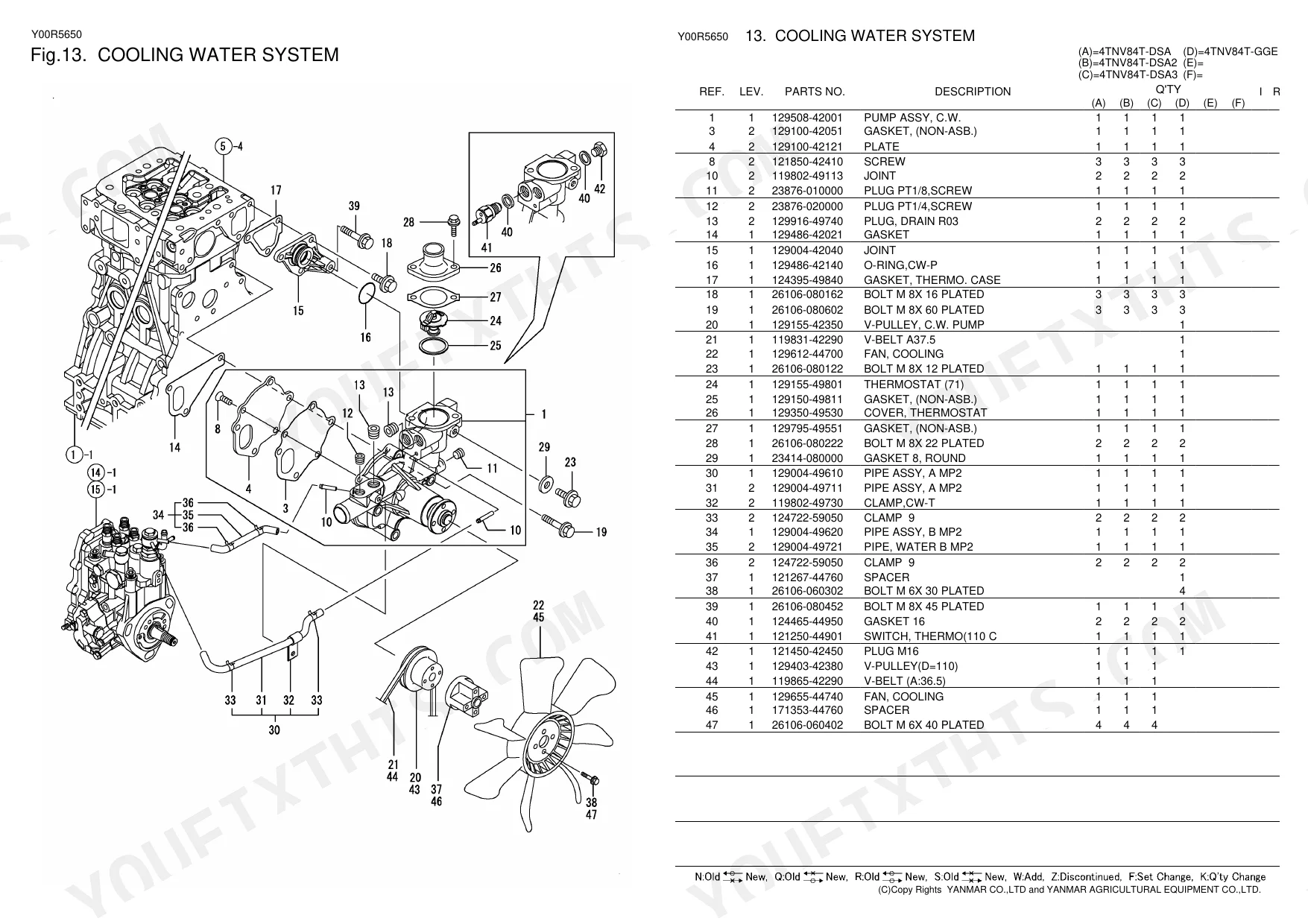
Open the cooling parts exploded view on page 19, which shows the C.W. Pump Assy, thermostat case, cooling fan, and related pipe assemblies as individual items. Identify whether you need the complete pump assembly or a sub-component. The system thermostat opens at 71°C; add the thermostat and matching case gasket to the same order to avoid a return trip. p. 19
How do you fix exhaust manifold gasket part number unclear when multiple gaskets appear in the same exploded view?
Turn to page 13, the exhaust manifold diagram. The EXH.MANIFOLD Gasket is listed as a discrete line item, separate from the manifold casting and bolt hardware. Locate it by position number in the exploded view, then verify the part number against the index on page 3. Order manifold bolts as separate line items; they are not included in the gasket entry. p. 13
How do you fix intake heater part number buried among hose and clamp listings on the intake manifold diagram?
Check page 12, which groups the Heater together with intake manifold hoses, gaskets, and clamps in the exploded view. Isolate the heater by its position number rather than searching by description alone, as it sits between hose and clamp entries. Cross-reference page 22 for any associated electrical connector parts that may be cataloged under a separate electrical assembly. p. 12
How do you fix turbocharger gasket kit part numbers needed for RHF4 unit, inlet and outlet gaskets listed separately?
Go to page 15, which covers the RHF4 turbocharger assembly. Inlet and outlet gaskets appear at different positions in the exploded view and carry distinct part numbers; do not assume they are interchangeable. Stud bolts and nuts are cataloged as individual line items alongside them. Verify all position numbers against the parts list on page 3 before submitting the order. p. 15
What do I get after purchasing this Yanmar 4TNV84T-GGE & variants manual?
A 40-page Parts Catalog in searchable PDF format, available the moment you complete checkout. View on computer, tablet, or phone, with no shipping wait.
Can I print this manual?
Yes, print as many copies as you want, and there are no restrictions. Many mechanics print the section they need and bring it to the shop floor.
Reviews
There are no reviews yet.