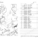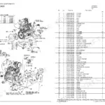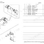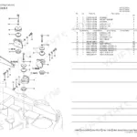


Part of the Yanmar Parts Manuals.
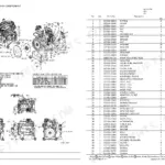
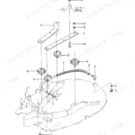
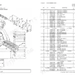
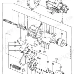
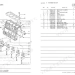
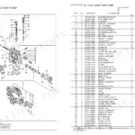
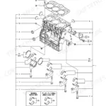
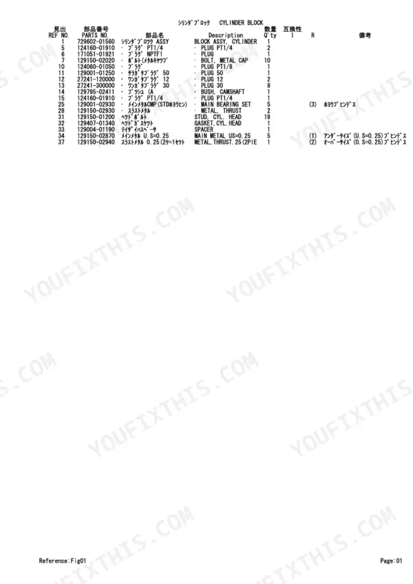
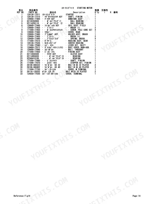
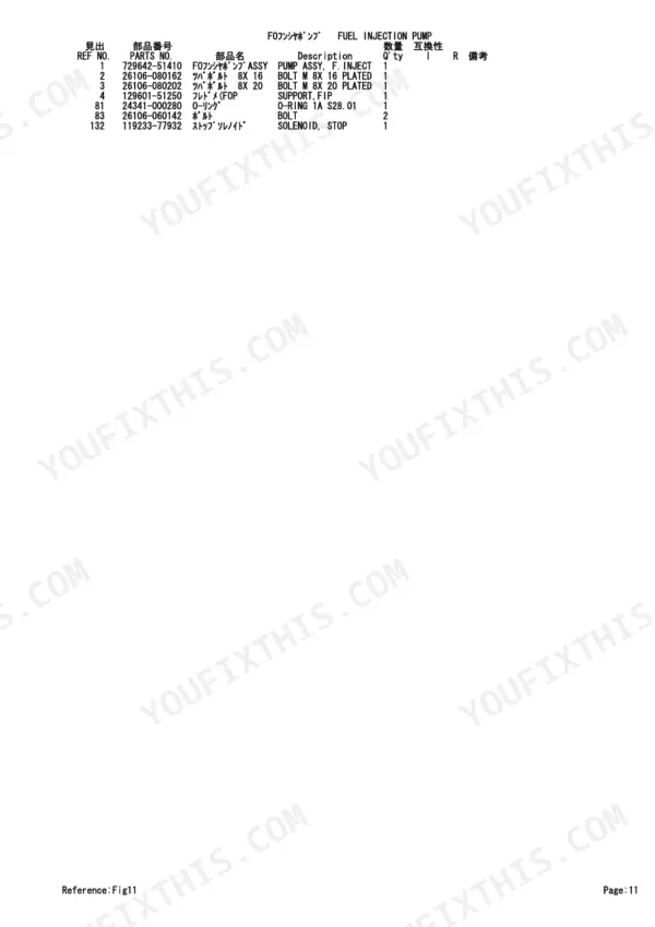
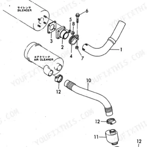
All 42 pages of this Yanmar TB145 4TNV88-QTB Parts Catalog cover one engine family in three configurations: QTB(cab), QTB1 canopy, and the full TB145 compact excavator application. Inside, exploded-view figures walk every major assembly: cylinder block, gear housing, flywheel housing and oil sump, crankshaft and piston, lubrication system, fuel injection pump with inner parts and governor detail, fuel injectors, starting motor, generator, and a complete gasket set. You get factory part numbers and cross-references for each component, from main bearing sets and camshaft gearing down to individual O-rings, valve stem seals, and delivery valve assemblies. The cooling system diagram notes thermostat opening temperature at 82°C: the kind of embedded factory data that confirms this is the OEM source document, not a reprint. Ordering the wrong part means two days of waiting. Bookmarked by assembly, this PDF lets you search any part name and land on the right figure in seconds.
Other edition of this manual
What's Inside This Parts Manual
| System | Pages | Key Topics |
|---|---|---|
| Cylinder Block | 5-6 | Block Assy, Cylinder, Plug, Bush, Camshaft, Main Bearing Set, Gasket, Cyl. Head |
| Gear Housing | 7-8 | Gear Case Assy, Plug, Seal, Oil, Cover Assy, Pump, Valve, Relief |
| Flywheel Housing & Oil Sump | 9-10 | Parallel Pin, Housing, Flywheel, Cap, Flywheel Cover, Spacer, Oil Sump, Sump Assy |
| Cylinder Head & Bonnet | 11-12 | Hed Assy, Cylinder, Guide, Valve, Intake |
| Suction Manifold & Air Cleaner | 13-14 | |
| Exhaust Manifold & Silencer(cab) | 15-16 | |
| Exhaust Manifold & Silencer( for QTB1)(canopy) | 17-18 | |
| Camshaft & Driving Gear | 19-20 | |
| Crankshaft & Piston | 21-22 | Crankshaft Assy, Gear, Piston Assy, Ring Set, Connecting Rod, Piston Pin |
| Lub.Oil System | 23-24 | Dipstick, Pipe Assy, Lub. Oil, Cooler Assy, Oil, Filter, Joint Bolt |
| Cooling Water System | 25-26 | Pump Assy, Water, V-Pulley, Fan, Cooling, Thermostat, Radiator Assy |
| Fuel Injection Pump | 27-28 | Pump Assy, F. Inject, Support, Fip, O-Ring, Solenoid, Stop |
| Fuel Injection Pump (Inner Parts) | 29-30 | Valve Assy, Dilevery, Timer Set, Piston, Damper Assy, Pump Assy, Feed |
| Governor (Inner Parts) | 31-32 | Packing, Case, Lever, Regulator, Bolt, Idle Limit, Screw, Adjust |
| Fuel Injection Valve | 33-34 | Fuel Injector, Nozzle Assy, Holder Assy, Nozzle, Spring, Pipe Assy, Injection |
| Fuel Line | 35-36 | Bracket, Filter, Pipe Assy, Fuel Oil, Fuel Pump, Separator Assy, Element |
| Starting Motor | 37-38 | Shaft, Pinion, Armature Assy, Ball Bearing, Coil Assy, Field, Brush, Pinion Assy |
| Generator | 39-40 | Alternator, Rotor Assy, Ball Bearing, Flame Assy, Drive, Pulley, Regulator Assy |
| Gasket Set | 41-42 | Gasket, Cyl. Head, O-Ring, Seal, Valve Stem, Exh. Manifold |
Quick Reference Specifications
| Specification | Value | Page |
|---|---|---|
| Thermostat opening temperature | 82 | p. 26 |