


Part of the Yanmar Parts Manuals.
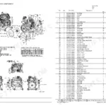
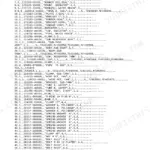
Looking for the right part numbers for your backhoe loader? This 173-page Yanmar CBL40 parts catalog PDF (OEM #0CS10-M42301EN) breaks down every exact component for your compact excavator. You get highly detailed exploded views of the entire drivetrain, hydraulic pump assemblies, and boom linkage, making component identification fast and accurate. Open to any system to find complete factory parts lists with exact OEM cross-references for the engine, cab, and undercarriage. Verify you are ordering the correct 55X35 mm lift cylinder seals or the exact 60.5 mm propeller shaft before tearing the machine apart. Stop ordering the wrong components from vague aftermarket diagrams. This bookmarked digital manual opens instantly on your phone or tablet, so you can match part numbers right at the workbench.
What's Inside This Yanmar CBL40 Parts Manual
| System | Pages | Key Topics |
|---|---|---|
| Fuel System | Air Cleaner, Accelerator Cable, Fuel Tank, Fuel Pipe | |
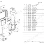
| Cooling System | Radiator & Mount | |
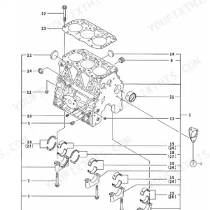
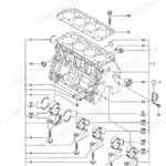
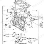
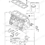
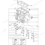
| Engine | Muffler, Oil Cooler, 126.Piston | |
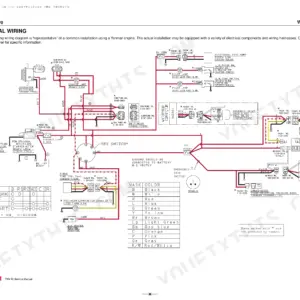
| Electrical System | Battery, Starter Switch, Work Lamp, P.T.O. Switch | |
| Clutch & Transmission | Transmission Accessories, Transmission Stay, Front Transmission Case, Rear Transmission Case, Transmission Input Shaft, 119.P.T.O. Clutch, Transmission - Return | |
| Rear Axle, Differential & Brakes | 111.Rear Axle Case, 115.Brake, 123.P.T.O. Brake Shaft, Brake | |
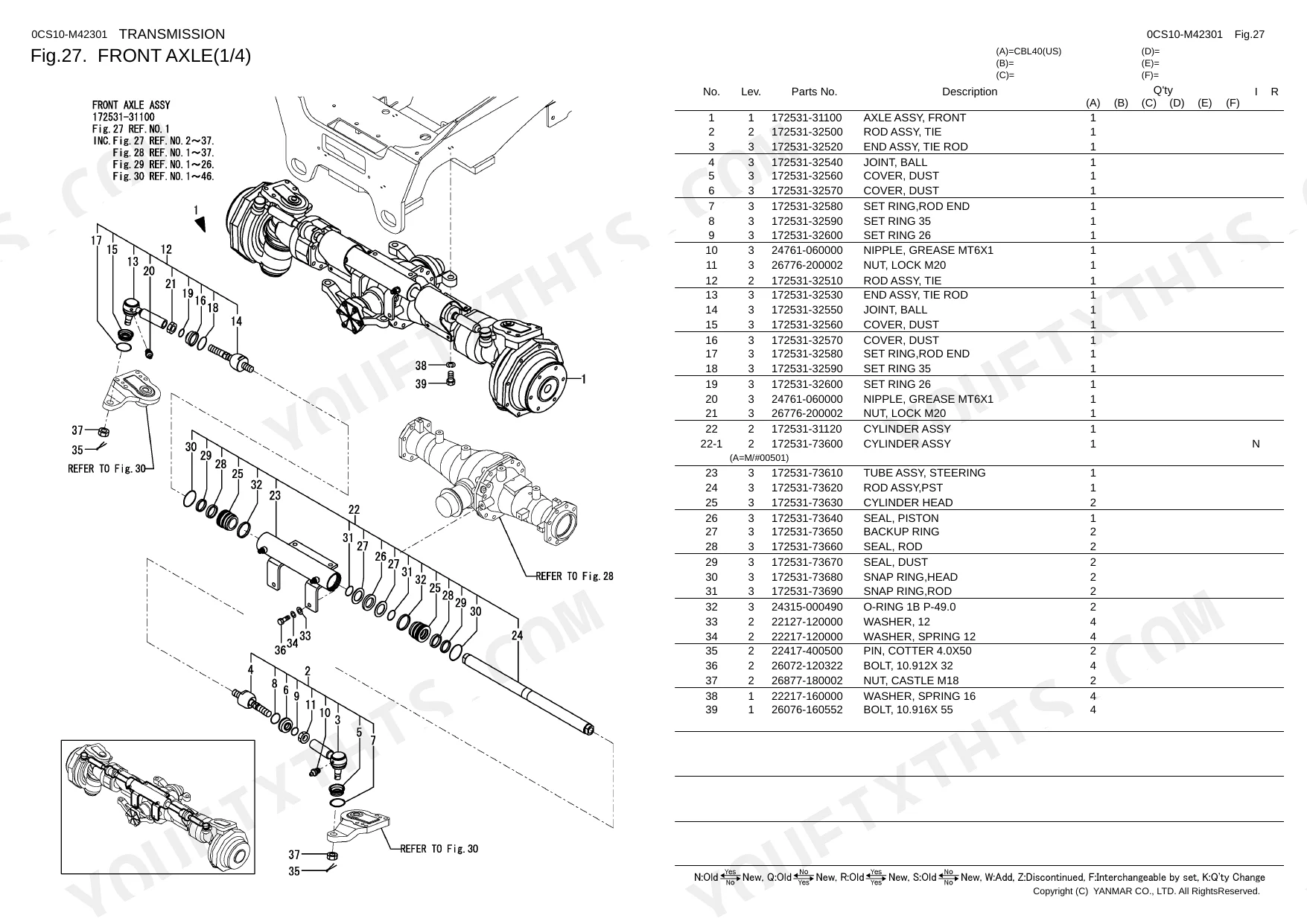
| Front Axle & Steering | Propeller Shaft, Front Axle, Steering Wheel & Column, Steering Unit, Steering | |
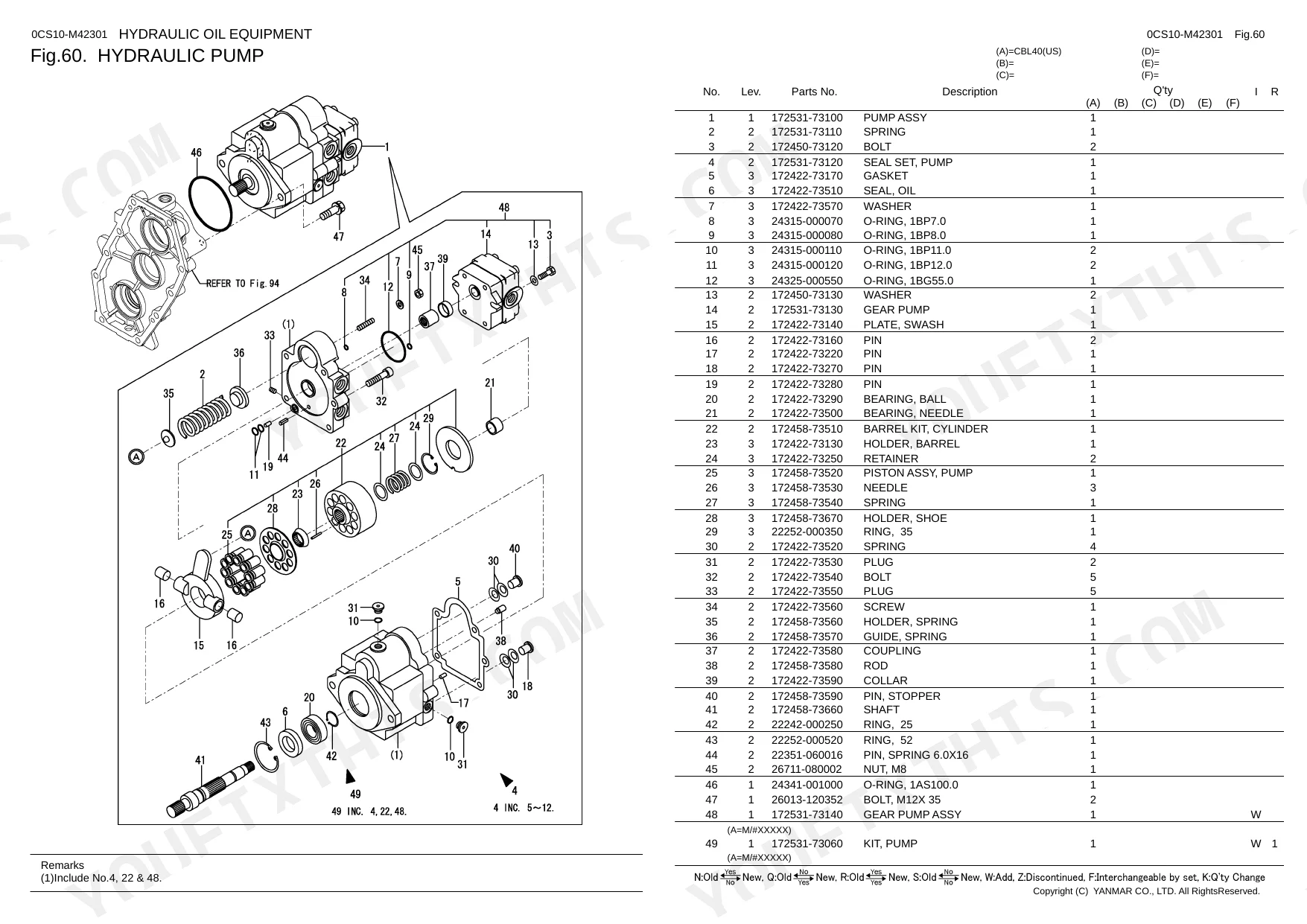
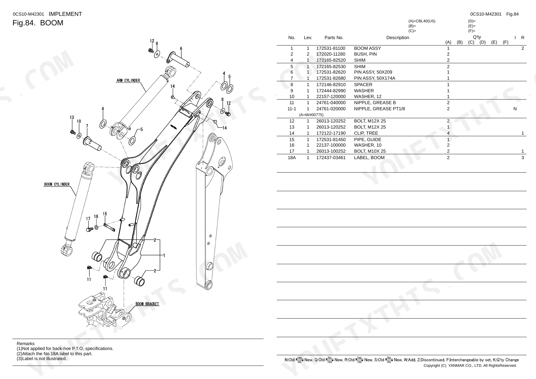
| Hydraulics & 3-Point Hitch | 102.Pump Shaft, 116.P.T.O. Valve, 121.P.T.O. Pump, Lift Arm Lock, Lift Cylinder, Dump Cylinder, Boom Cylinder, Arm Cylinder, Swing Cylinder, Bucket Cylinder, Stabilizer Cylinder, Hydraulic Pump, Control Valve, Pilot Check Valve, 125.Hydraulic Cylinder Case, 128.Control Valve | |
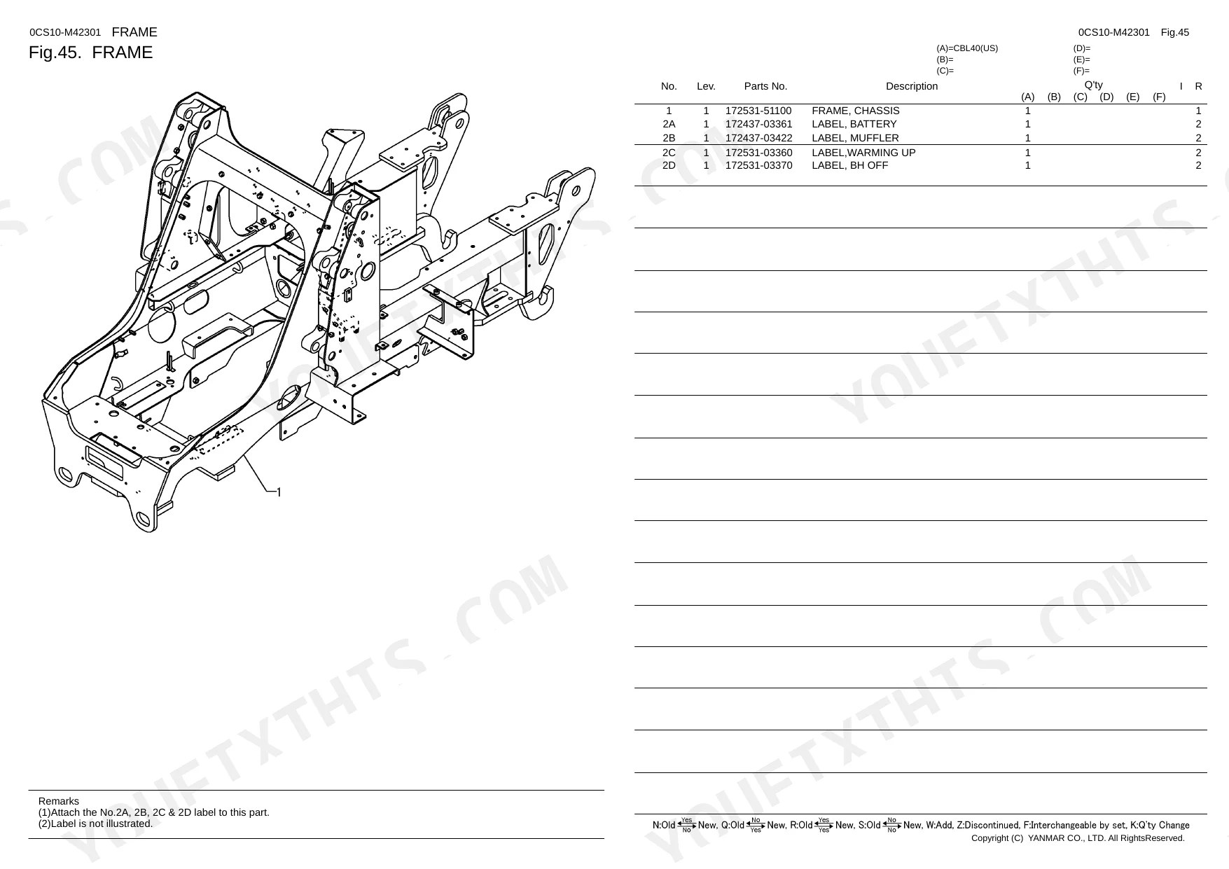
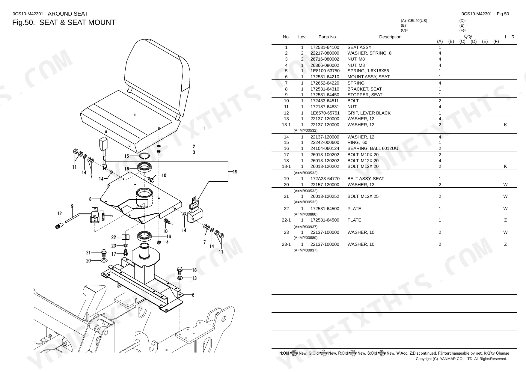
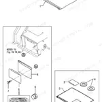
| Body & Operator Station | 124.P.T.O. Shaft Cover, Frame, Cover, Fender & Handrail, Step & Floor Mat, Seat & Seat Mount, Hood, Canopy, Hyd. Oil Tank, Boom Bracket, 133.Front Guard Kit | |
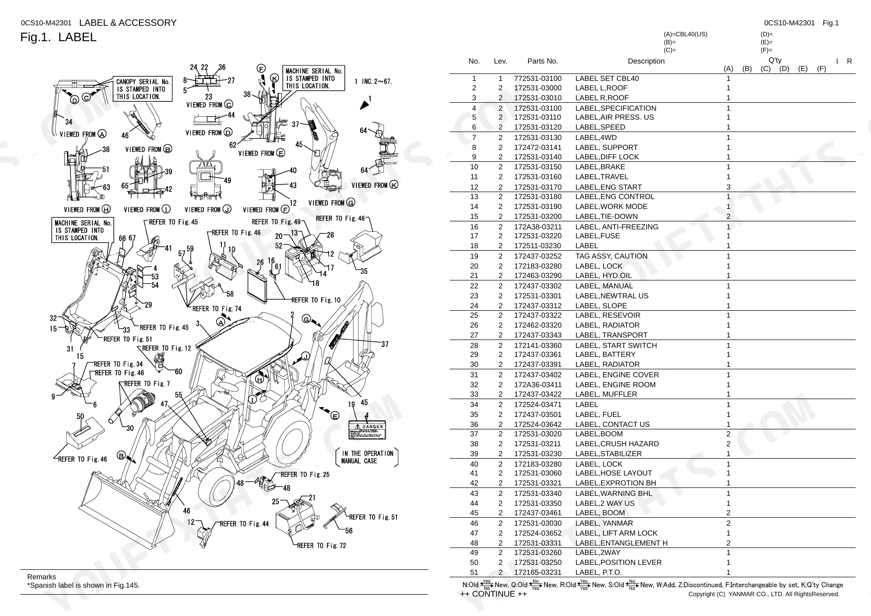
| Decals & Accessories | Label, 145.Label, 146.Label | |
| Other Components | Reference Materials, Emblem, Engine Mount, Around the Engine, Instrument Panel, Damper Disk, Drive Shaft, Input Shaft, Idle Shaft, Output Shaft, 100.Planetary Gear, 101.Motor Shaft, 103.Pinion Gear, 104.Sub Shift Shaft, 105.Front Drive Shaft, 106.4 Wheel Drive Shift |
Quick Reference Specifications
| Specification | Value | Page |
|---|---|---|
| Propeller shaft diameter (No.8, 11-1) | 48.6 mm | p. 34 |
| Propeller shaft diameter (No.8-1, 11-2) | 60.5 mm | p. 34 |
| Lift cylinder seal dimensions (No.7) | 55X35 mm | p. 34 |
| Dump cylinder seal dimensions (No.7) | 55X30 mm | p. 98 |
Yanmar CBL40 Common Problems This Manual Covers
Need the correct Yanmar CBL40 propeller shaft replacement part number for severe vibration and worn splines
Inspect the exploded diagram on page 34 to identify your specific driveline. Measure your existing unit. If the shaft diameter is 48.6 mm, use the standard part. If it measures 60.5 mm, order the heavy-duty variant to match your assembly.
Manual Section: Propeller Shaft p. 34Can't identify the right dump cylinder seal kit part number for a leaking front loader bucket
Check the hydraulic component breakdown on page 98 to find your exact parts. Verify the required seal set matches the 55X30 mm dimensions listed for item number 7. Cross-reference this specific size with your cylinder rod to ensure you order the correct replacement kit.
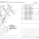
Manual Section: Dump Cylinder p. 98Looking for the exact hydraulic oil tank replacement number for a cracked reservoir near the bottom weld
Review the tank housing layout on page 116 to identify your exact assembly. Check your current reservoir wall thickness before ordering replacement parts. Specify the standard 6 mm plate version or the reinforced 12 mm option depending on your machine's factory configuration.
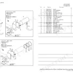
Manual Section: Hyd. Oil Tank p. 116Trying to find the relief valve O-ring part number for a persistent valve block pressure leak
Locate the control block schematic on page 121 to find the correct hardware. Find item number 4 and confirm the required O-ring measures exactly 2.5X23 mm. Use this precise dimension to source the exact factory seal and prevent system pressure loss during heavy lifting.
Manual Section: 129.Relief Valve p. 121Frequently Asked Questions
How do you fix need the correct Yanmar CBL40 propeller shaft replacement part number for severe vibration and worn splines?
Inspect the exploded parts diagram on page 34 to identify your specific driveline. Measure your existing unit. If the shaft diameter is 48.6 mm, use the standard part. If it measures 60.5 mm, order the heavy-duty variant to match your assembly. p. 34
How do you fix can't identify the right dump cylinder seal kit part number for a leaking front loader bucket?
Check the hydraulic component breakdown on page 98 to find your exact parts. Verify the required seal set matches the 55X30 mm dimensions listed for item number 7. Cross-reference this specific size with your cylinder rod to ensure you order the correct replacement kit. p. 98
How do you fix looking for the exact hydraulic oil tank replacement number for a cracked reservoir near the bottom weld?
Review the tank housing layout on page 116 to identify your exact assembly. Check your current reservoir wall thickness before ordering replacement parts. Specify the standard 6 mm plate version or the reinforced 12 mm option depending on your machine's factory configuration. p. 116
How do you fix trying to find the relief valve O-ring part number for a persistent valve block pressure leak?
Locate the exploded parts diagram on page 121 to find the correct hardware. Find item number 4 and confirm the required O-ring measures exactly 2.5X23 mm. Use this precise dimension to source the exact factory seal and prevent system pressure loss during heavy lifting. p. 121
What format is this manual in?
You get a 173-page searchable PDF that downloads instantly after checkout. Open it on your laptop, tablet, or phone, and bring it right to the shop floor.
Am I able to print pages from this manual?
Yes — the PDF is DRM-free. Print whatever sections you need to take out to the shop. Standard letter or A4 paper works.
Reviews
There are no reviews yet.